1. Introduction
Due to the fact that air pollution has become a global problem, alongside economic issues, governments and academical institutions have been making progress to establish a clean, efficient, and environmentally sustainable urban transportation system that uses electric vehicles (EVs) [
1,
2]. EVs have the potential of having major impacts on energy, the climate and transport, as well as on the advancement of hi-tech, the creation of new industries, and economic development. EVs have been known as the main direction of the automotive industry’s transformation and development in the 21st century [
3]. The main technologies for the production of EVs include body design, energy system and management, motor drive system, and system-level optimization. In body design, aerodynamics drag will be considered to give a vehicle on the road a better performance. The motor drive system, which consists of three main components (control, power converter, and motor), is an essential part because it is a power conversion unit that has a significant impact on the performance of EVs. The DC motor drive was initially adapted in EVs but its commutator and brush require regular maintenance. However, with the advancement of motor drive control engineering, computer technologies, and permanent magnet materials, many proposed advanced motor drive technologies, such as induction motors, permanent magnet synchronous motors (PMSM), and switched reluctance motors (SRM), now offer better performance than DC motors [
4]. For several years, the study of high-performance drive motors for EVs has therefore been a research priority [
5]. Among them is the PMSM, a rotating synchronous machine with permanent magnets on the rotor and a three-phase stator with sinusoidal distributed windings, which is a competitive alternative over traditional AC motor for EVs [
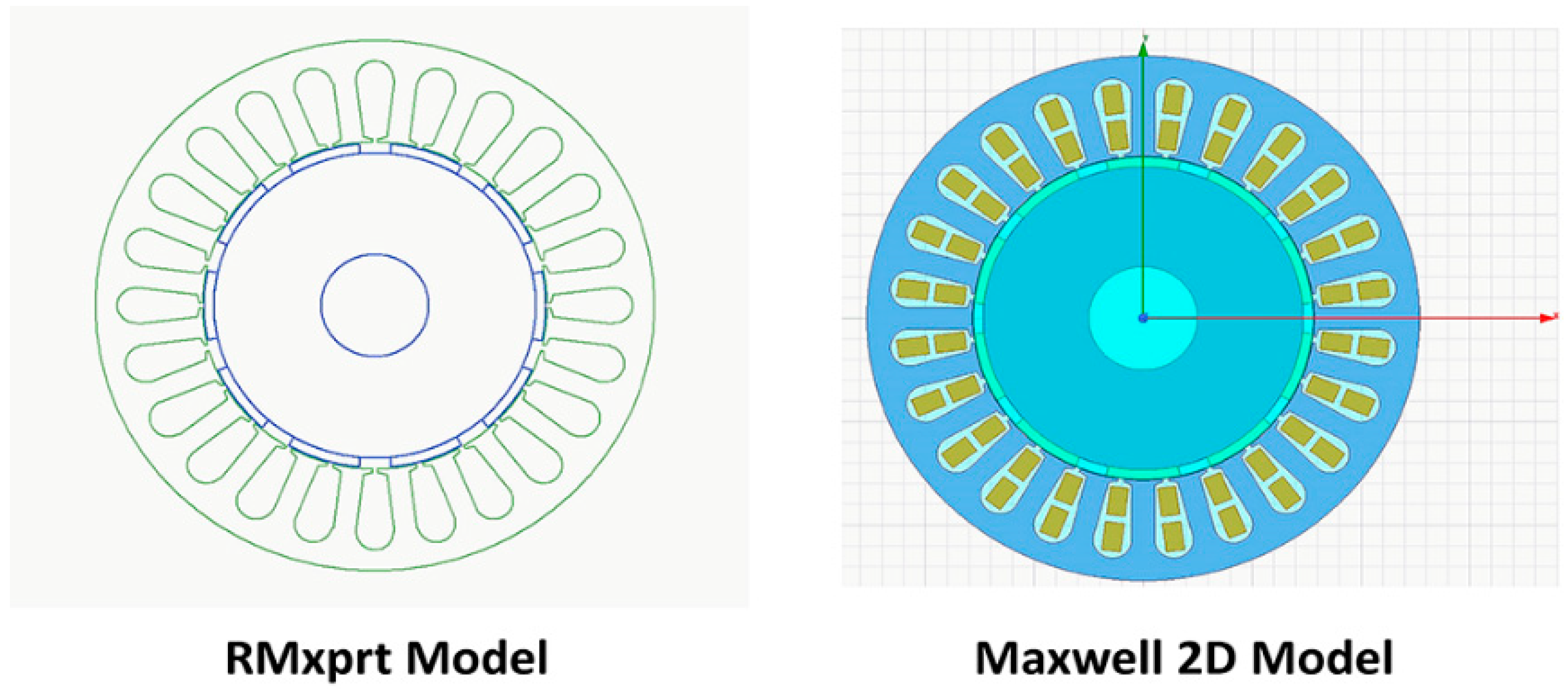
6]. Their main advantages include high efficiency, which is due to the use of permanent magnets for excitation that consume no power, and high-power density which can produce high flux densities and high torque. A synchronous electric motor drive utilizing permanent magnets uses the finite element analysis (FEA) technique to estimate the motor’s electromagnetic parameters. This is accomplished via the use of Ansys Maxwell/Simplorer, which allows the integration of FEA-generated models into a system simulation [
7]. Several components, such as electrical machines, which are comprised of nonlinear dynamic systems, should be modeled using FEA in order to accurately represent the device’s output. Software tools based on the FEA method are flexible for dynamically linking with the external control drive circuit simulator. After having an understanding why electric motors are of great interest, this study deals with a brief overview of the state of the art, as follows: first looking at the PMSM and second the controls. Knowing the state of the art of the PMSM motor and its controls, the next step will deal with a technical bibliography for detailed modeling and valid system simulation as well as the controls of PMSM, which is an essential step before implementing the controls in experiment. Many measurements must be determined when designing a motor, but the main and decisive element is the motor’s size, since proper functioning of the motor and the required flux induction depends on the area involved. This paper chose a pear-shaped groove because it can minimize core loss and pulsating loss effectively, and because its groove area usage rate is high. In the design to decrease the torque ripple, the PMSM’s electromotive force and torque ripple waveforms must also be considered. As a result, the flux density of the air gap should be under the saturation limit to avoid an increase in cogging torque.
Various research has conducted FEA analyses on the PMSM drive. Sun et al. [
8] considered the PMSM design, analysis, and optimization for EVs being used for campus patrols with such a specific drive cycle. The coupling of Ansys and MATLAB software for precise design and optimization of systems is shown in [
9]. The motor model in Maxwell 2D, power converter model in Ansys Simplorer, and MATLAB/Simulink for the control model comprise the drive’s system model. Chen and Zhou [
10] proposed a co-simulation technique for modeling brushless DC motor speed control systems based on Maxwell, Simplorer, and Simulink. Wu et al. [
11] use a Finite-Element Method (FEM) coupled field-circuit to present an efficiency optimization method for PMSM drive in hybrid electric vehicle or electric vehicle application. Ansys created a 2D-Maxwell FEM model of a 15 kW PMSM, while Simplorer created a model of a vector control circuit. A typical HEV is designed and analyzed using VHDL-AMS, one of the hardware description languages, for simulation and modeling of PMSM utilized in electric vehicles, modeled and investigated in [
12]. Kachin et al. [
13] discuss how to simulate PMSM using numerical methods implemented in Ansys 2D-Maxwell and Simplorer. In this article, the complete model is comprised of an inverter produced in Simplorer and a PMSM constructed in Maxwell. The vector control has been mentioned [
14,
15], which was deployed on PMSM. Performance of the vector control is a perfectly acceptable method of getting rapid response, even at extremely high-speed ranges. FEA software tools, such as Ansys Maxwell, AMESim, JMAG and Cedrat Flux, allow co-simulation with external drive control software, such as MATLAB-Simulink, PSpice, and PSIM. Basnet and Pillay [
16] present a co-simulation platform based on JMAG and MATLAB for a variable flux PMSM of an electric vehicle motor. The co-simulation results were compared with a conventional (dq-mathematical model) simulation, and the experimental tests show a more highly accurate result. In the above published literature, PMSM modeling and simulation were presented, and used different software to obtain high performance and precision. However, none of them have considered a co-simulation with a double closed-loop control algorithm (FL and PI controller), based on Ansys and MATLAB, to overcome the difficulty to control PMSM, since they show nonlinear dynamic behavior that varies in time.
The aim of this paper is therefore to develop a novel alternative for the modeling and simulating of PMSM and its control for electric vehicles, using Ansys and MATLAB. With this goal in mind, a valid model including the PMSM’s dynamics and electrical principles was developed, resulting in useful system observations and the best method to solve the optimization time problem.
Overall, the structure of this paper comprises five sections. In
Section 2, the modeling of a PMSM and power circuit using Ansys is mentioned.
Section 3 presents the design of the control structure by using Twin Builder and Simulink.
Section 4 shows the motor performance after performing simulation.
Section 5 presents the conclusion.
3. Co-Simulation (Maxwell/Twin Builder/Simulink)
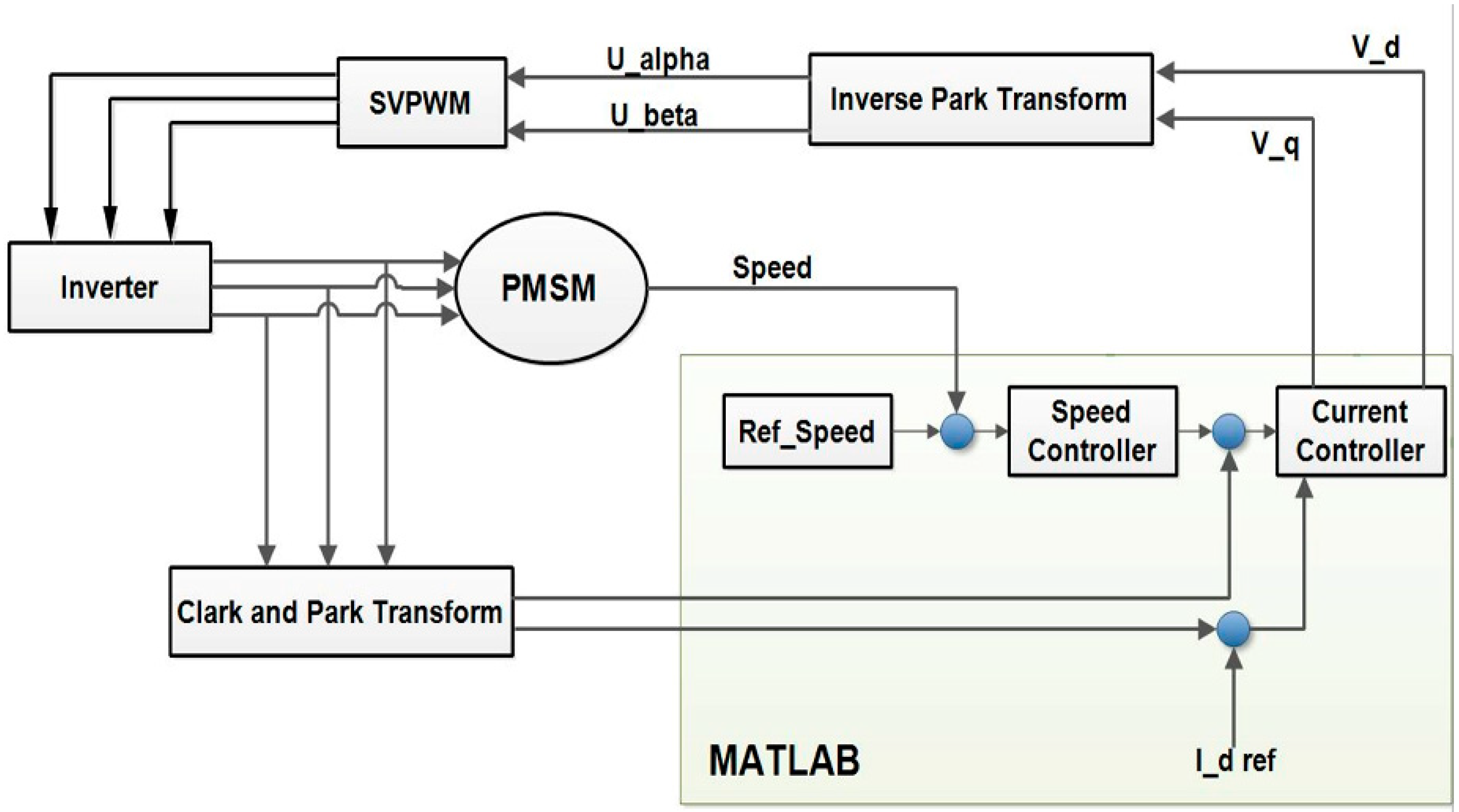
The control structure utilized here is focused on field-oriented control (FOC), which ensures good dynamics, robustness, and high efficiency [
19]. The control structure mainly includes the speed and current control double closed-loop, inverter unit and coordinate transformation unit, and space vector pulse-width modulation (SVPWM) algorithm module, as shown in
Figure 2.
The basic idea of the control principle is by using a coordinate transformation to obtain two orthogonal components, field current (Id) and torque current (Iq). Electromagnetic torque is mainly generated by torque current, and adjusting field current will change the air gap magnetic field [
20]. Six IGBT switches and six stream diode modules form the output signal in the three-phase PWM inverter. The generation of control signals in a PWM inverter control circuit is achieved by comparing it to a triangle signal, with the same period to the switching period, through the SVPWM control module. Due to the inability of a two-dimensional Maxwell motor model to incorporate phase winding resistance Rs and concentrated phase end-winding inductance “Lend,” these components are added in the Twin builder model along with the PWM inverter.
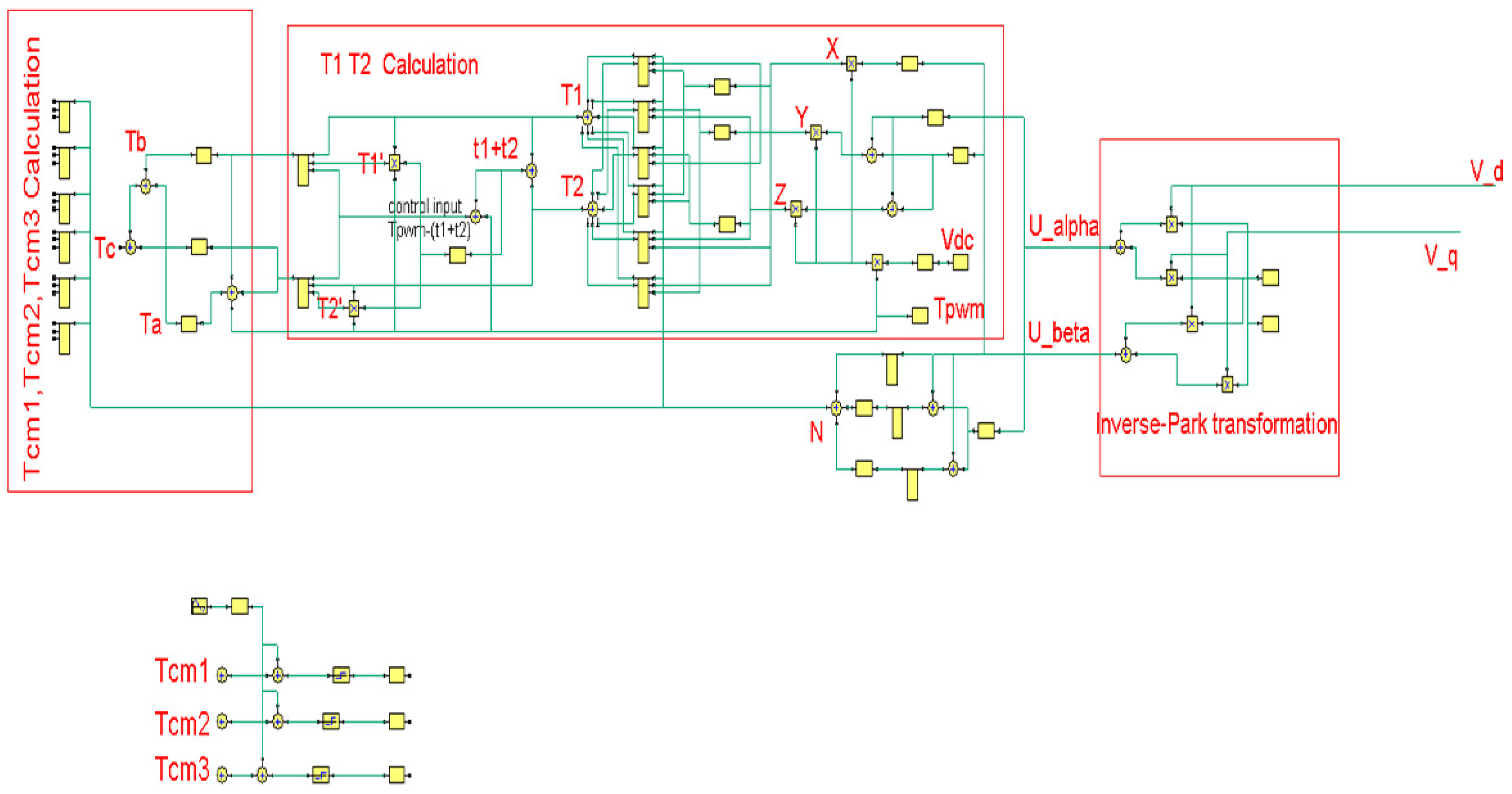
SVPWM is a technique for determining modulated pulse-width signals for inverter switches to provide the required three-phase voltages to an AC motor. The basic idea is to use the ideal flux circle of the AC motor as the base circle, and when the AC motor is driven by a symmetrical three-phase sinusoidal voltage, to approach the ideal flux circle with the actual flux circle generated by the inverter’s six power switches.
This results in the motor achieving a rotating magnetic field, resulting in high efficiency. Four major sub-modules comprise the SVPWM module, as follows: the main vector’s operating time calculation, the sector judgment, and the triggering pulse generating and switching point calculation, as shown in
Figure 3.
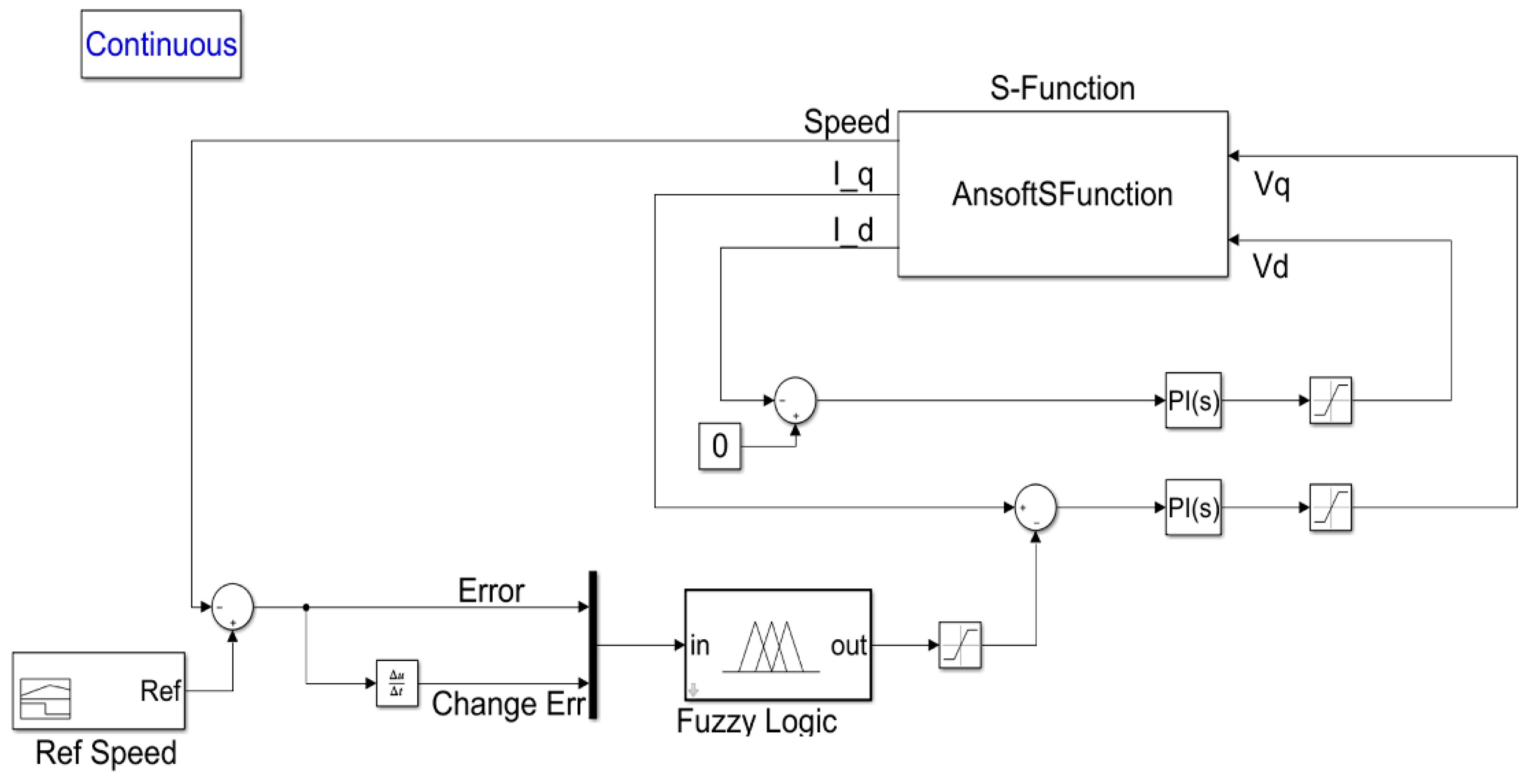
In the MATLAB/Simulink environment, we developed a double closed-loop system for controlling the motor’s speed and current signals, which is composed of fuzzy logic (FL) and a proportional integral (PI) regulator, as shown in
Figure 4. For PMSM control, the PI field-orientation control technique is very common and useful. However, an advanced motor controller is required to achieve high performance and system stability and robustness. The FL controller has been increasingly implemented in complicated control systems in today’s technologies [
21]. The FL controller was developed with two inputs and one output. Current in axis d (I
d) was kept to zero in this paper, thus we used the FL controller to get the reference current value in axis q (I
q,ref), which were then compared to the actual I
q values in order to get the voltage in axis q (V
q) values. In the FL controller, the inputs are as follows: speed error “Error”, change in speed error “Change Err”, and an adjusted output control ”Control” using control rules. There are five membership functions for input variables, as follows: “Error”:—Very low, Medium Low, Zero, Medium High, Very High. Besides these, there are also two further membership functions for input variable, as follows: “Change Err”:—Positive High and Negative High.
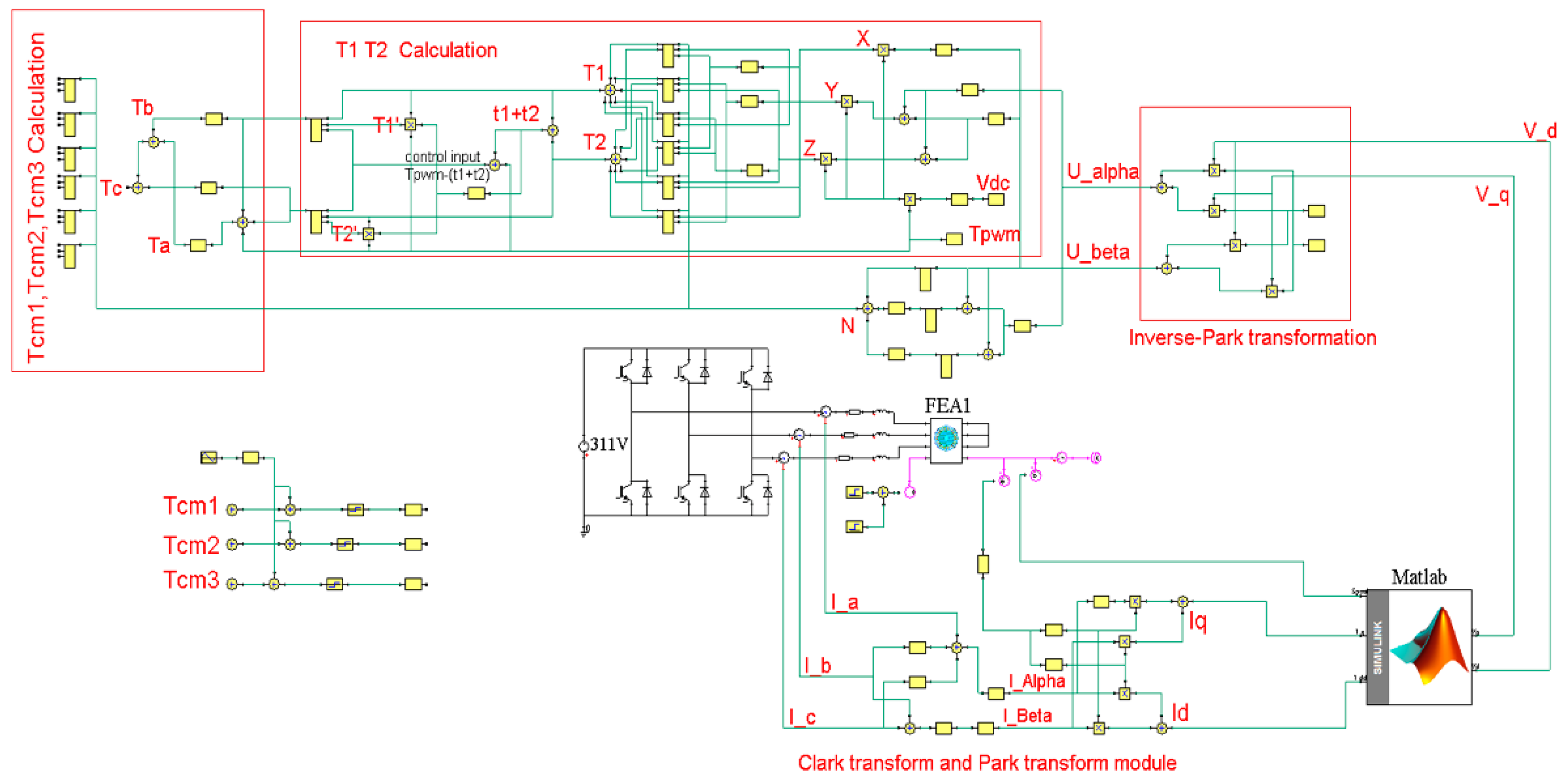
Finally, after developing the speed and current control circuits in Simulink, a co-simulation between Twin builder and Simulink is established for the purpose of implementing and simulating the overall motor drive control system. A co-simulation is simply a connection between the software packages ANSYS and MATLAB that enables the flow of data and system control between the two packages. To run the co-simulation effectively, continuous data exchange across all of the individual components (Twin builder, Maxwell and MATLAB models) is required. The interface between Ansys and Simulink was established and implemented using a predefined “S-function” found in the Simulink component library provided by ANSYS. The S-function’s objective is to receive d- and q-axis currents and motor’s speed from Maxwell motor model, and to transfer d- and q-axis voltages to the inverse park transformation in Twin builder. It functions as the data interface between Twin builder and MATLAB since there is not any direct data exchange among Ansys-Maxwell and MATLAB. The Simulink control structure was then exported to Twin Builder as seen in the complete model of Ansys and Simulink control structure in
Figure 5.
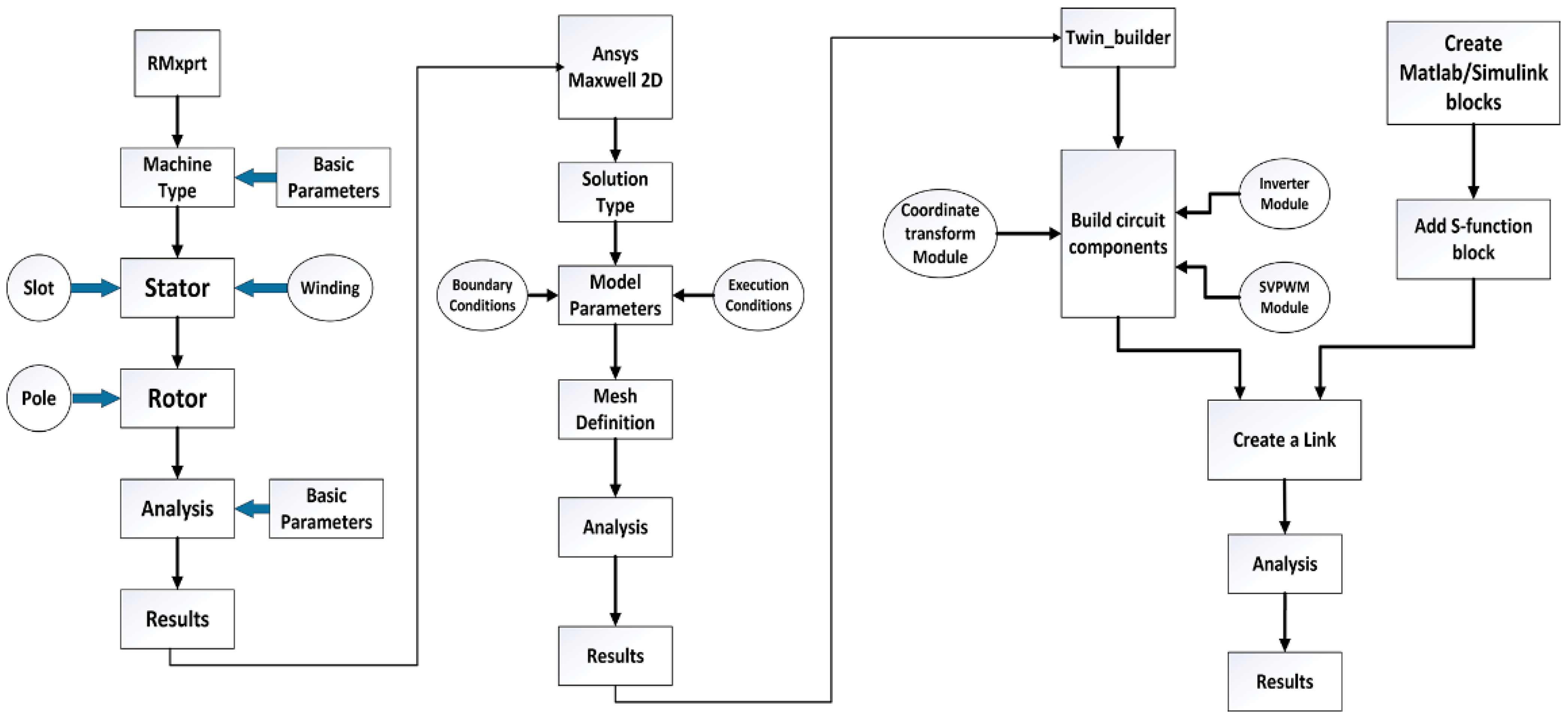
Such a simulation approach will be useful for detailed modeling with higher accuracy and system optimization. First, the Simulink– Twin builder co-simulation is achieved by adding (link to) a sub circuit of Simulink component to Twin builder circuit, where the results of the simulation are displayed in the graphical environment of Twin builder. Secondly, MATLAB’s S-Function (provided by the Ansys Software Manufacturer) is created with the required name ‘AnsoftSFunction’ in Simulink using the Sim2Sim link interface. The S-function’s objective is to receive d- and q-axis currents and motor’s speed from Maxwell motor model, and to transfer d- and q-axis voltages to the inverse park transformation in Twin builder. It functions as the data interface between Twin builder and MATLAB since there is not direct data exchange among Ansys-Maxwell and MATLAB. The overall flow chart of the co-simulation of these software tools is shown in
Figure 6.
4. Simulation Result
Through Maxwell, Twin Builder, and Simulink, a dynamic model and control structure of permanent magnet synchronous motor (PMSM) is proposed. In the Twin Builder environment, the simulation model components are interconnected to each other. The PMSM parameters are as follows: the stator resistance of 0.448 Ohm, the inductance 0.080378 mH, the rotational inertia of 0.067 kg/m
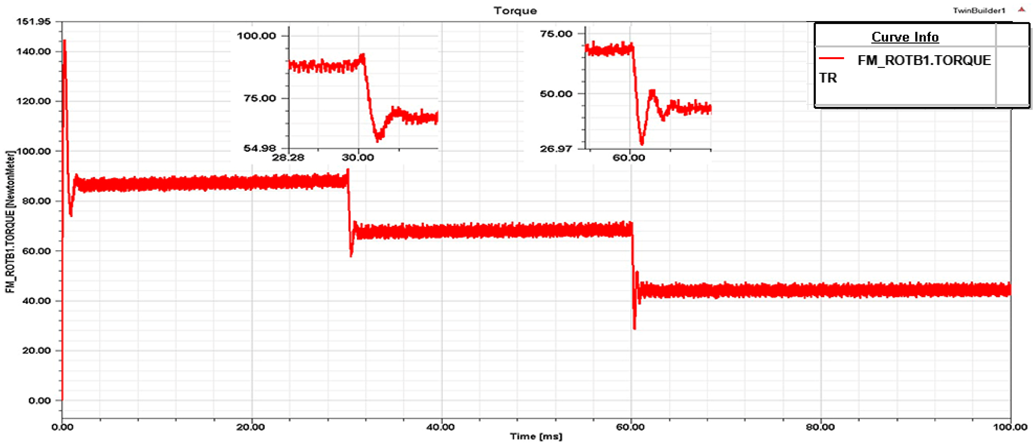
2 and IGBT switch frequency of 10 kHz with the initial given speed of 1000 rpm, set the rotational speed to jump to 1500 rpm at the 30 ms and 2500 rpm at the 60 ms, then run the simulation model for 100 ms to get the simulation results of the phase current, phase voltage, electromagnetic torque waveforms, flux-linkage, and d- and q-axis currents. It took 7 h 31 min to run the simulation for a minimum time step of 10µs and maximum time step of 0.1 ms, with the system configuration of 8 GB RAM, i7-4710 CPU @ 2.50 GHz processor. As can be seen from the simulation, the torque waveform is shown in
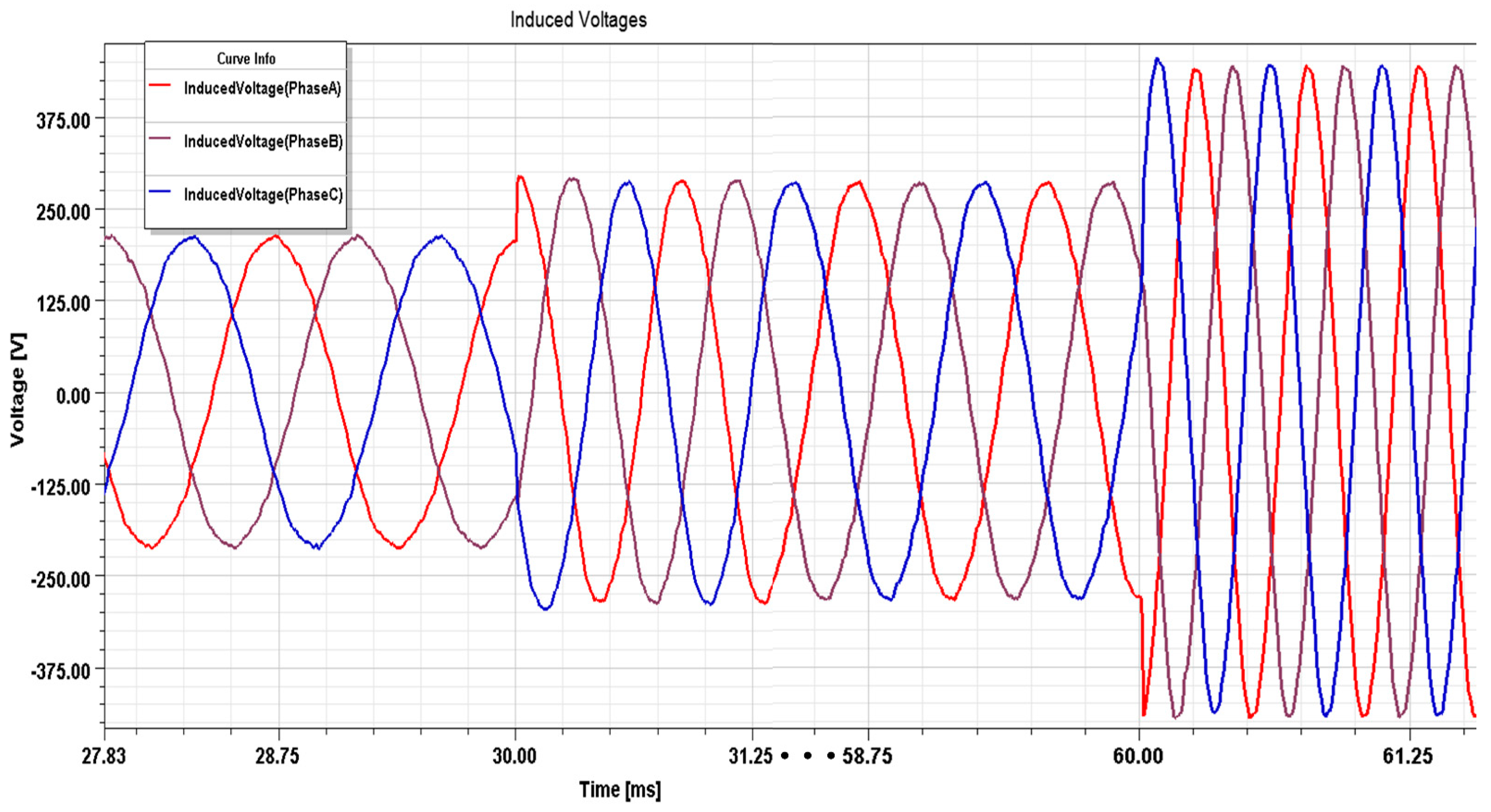
Figure 7, the motor is seen to be in the unbalanced zone for up to 1.08 ms at 30 ms and 1.36 ms at 60 ms, then stabilizes with the lowest value of 65 N m and 42 N m, the highest torque value being about 70 N m and 46 N m, and the average value being about 68 N m and 44.5 N m, with the torque ripple of less than 10%. Therefore, it could maintain the electric car stationarity while it is running. The three-phase input current and voltage outputs of the PMSM drive are shown in
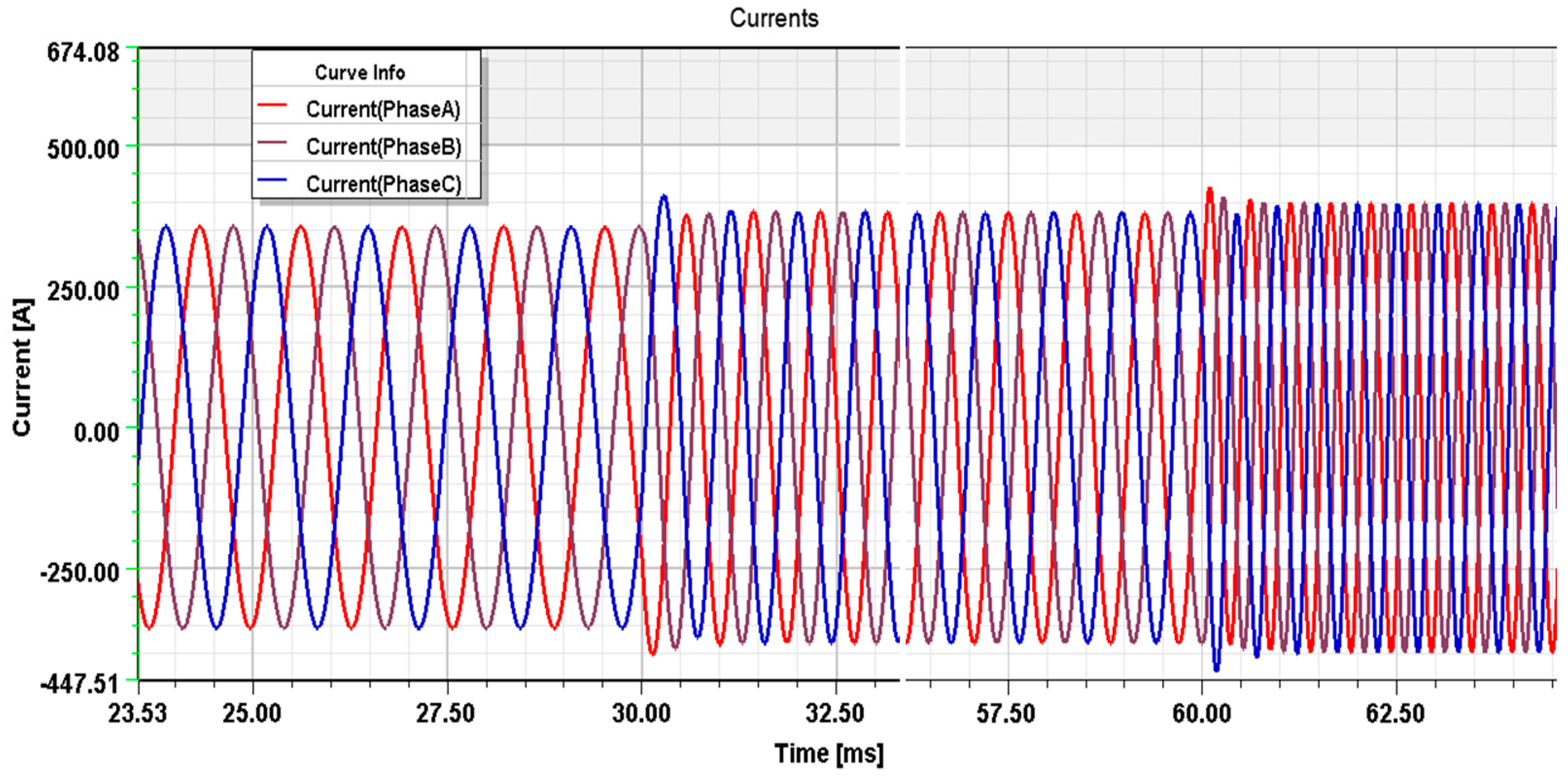
Figure 8 and
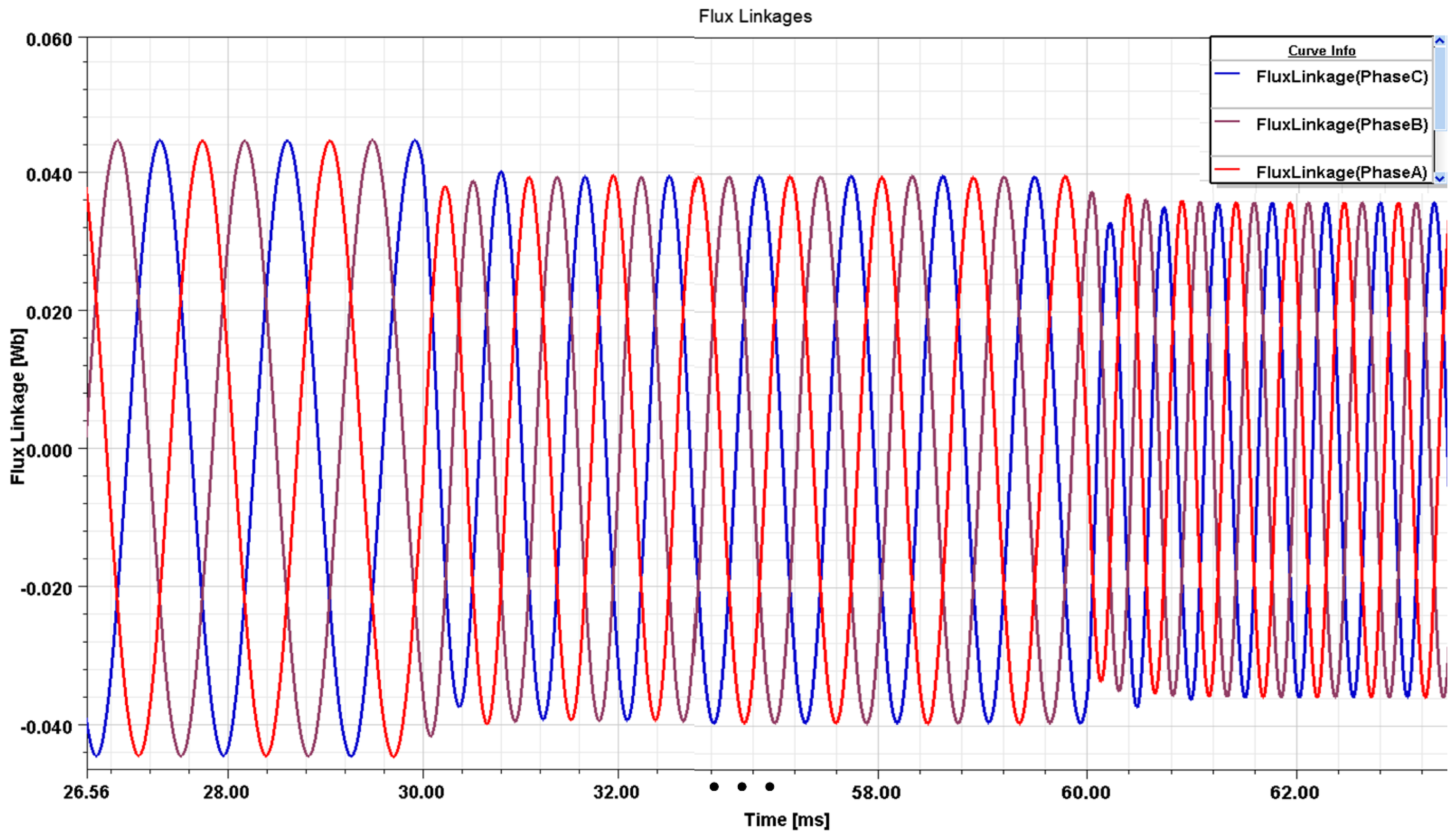
Figure 9, which shows non-sinusoidal waveforms at the start and at the time of speed change, but becomes sinusoidal after reaching steady state, thus confirming that it is sinusoidal. The voltage and current should have a 120° phase difference and equal magnitude with one another for the purpose of generating an appropriate rotational flux, which is consistent with theoretical theories. The stator currents measured with these voltages show the characteristic transient waveforms found in every article modelling PMSM. The simulation also calculates the flux linkage values across the three phase conductors in the stator.
Figure 10 illustrates each determined value from the simulation.
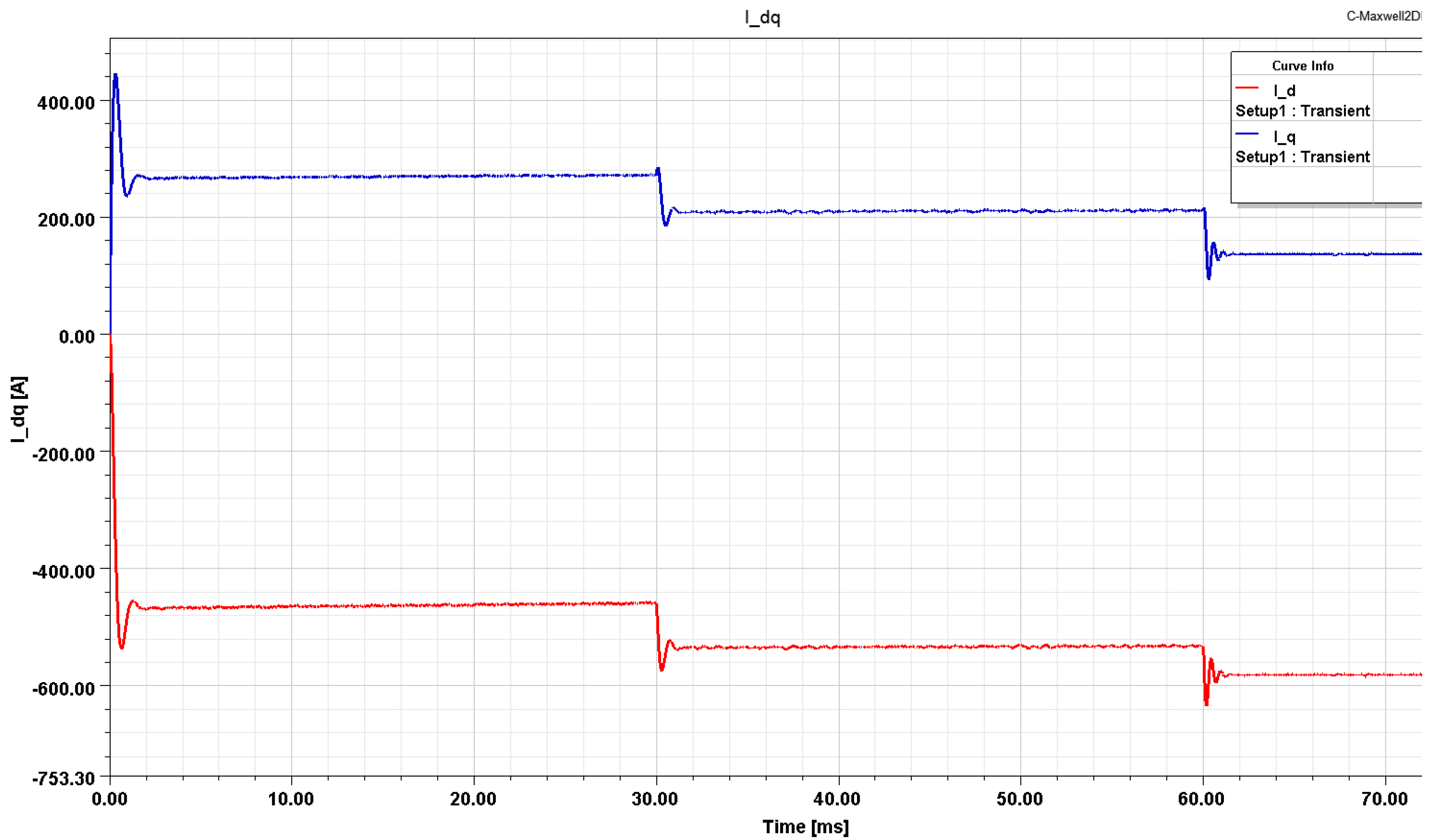
Figure 11 shows the waveform of current of d- and q-axis, which settles down after an average of 1.2ms because of the increase in the speed. Currents along the d- and q-axes might vary rapidly depending on the reference speed characteristics. It is important to note the sudden shift in all of these waveforms at 30 and 60 ms, when the speed increases. With regard to control currents, it is recognized that the q-current has the same waveform as the electric torque, showing the relationship between torque and q-current is linear.


