Article

Novel Battery Module Design for Increased Resource Efficiency

1
Fraunhofer-Institut für Fertigungstechnik und Angewandte Materialforschung, Wienerstr. 12, 28359 Bremen, Germany
2
Fraunhofer-Institut für Werkzeugmaschinen und Umformtechnik, Reichenhainer Straße 88, 09126 Chemnitz, Germany
3
Institut für Arbeitswissenschaft und Technologiemanagement, University of Stuttgart, Allmandring 35, 70569 Stuttgart, Germany
4
Fraunhofer-Institut für Arbeitswirtschaft und Organisation, Nobelstraße 12, 70569 Stuttgart, Germany
*
Author to whom correspondence should be addressed.
World Electr. Veh. J. 2022, 13(10), 177; https://doi.org/10.3390/wevj13100177
Submission received: 15 August 2022 / Revised: 15 September 2022 / Accepted: 19 September 2022 / Published: 23 September 2022

Abstract

:
The work presented focuses on a material efficient, modular design of a battery module for vehicle applications. Furthermore, the possibility of disassembly of individual components was considered. The constructive design focused on the combination of cast aluminum components, lightweight composites panels, and aluminum-foam phase-change material (PCM) composites. This led to an innovative battery module, which was finally implemented on a demonstrator level. The required cooling power of the module could be reduced by approx. 20% compared to conventional battery module setups. Furthermore, the constructive design of the module and the use of a “debonding-on-demand” technology enabled significantly faster disassembly. Die to the combination of these advantages and the possibility to give individual parts of the module a second life for new modules, the module shows a high resource efficiency as well as high CO2 savings potential.

1. Introduction

Efficiency and sustainability are crucial aspects of electric vehicle design. On the one hand, electric vehicles are seen as key factors in reducing the environmental impact of road traffic. On the other hand, the technology is not yet fully perfected. Electric vehicle production requires several critical or rare resources itself. Thus, increasing the efficiency of electric vehicles in order to reduce their use of resources and to ensure sustainability contribution is fundamental. Thereby, the battery is a significant factor and focal point, causing up to a third of the total weight and cost [1]. Currently, range and capacity, respectively, are unique selling points of a battery electric vehicle (BEV) even though most private trips are quite short and most commercial trips are well-known in advance [2]. In contrast, the battery’s size is critical for the economic and ecological use of natural resources (see, e.g., [3]). Thus, battery size and capacity should be scalable to the use case. For instance, public transit operators planning to electrify their fleet would not be limited to the small number of BEV models’ battery variants offered but could order individual configurations with a specific capacity, e.g., considering the topography, the share of urban and interurban routes, average travel speeds, etc., in their respective business area.
Accordingly, high flexibility in automotive battery design is important to remain responsive to differences in individual use cases such as private use, ride pooling, or commercial applications [4]. A new battery design needs to be developed that is scalable in terms of space, weight, and the usage of natural resources [5]. The battery needs to be adaptable and upgradable throughout its lifecycle phases, repairable when necessary [6], and disassembled at the end of its lifetime. In this context, innovative life-cycle engineering approaches to support engineers in evaluating their design decisions with respect to requirements of individual, varying life cycle paths of a product are gaining relevance [7]. This is especially valid with regard to the increasing spread of circular economy (CE) strategies and the focus they place on products’ later-stage life cycle phases, which is owed to the aim of decoupling value-creating activities, e.g., production, from the consumption of finite natural resources by replacing the ‘end-of-life’ concept with alternatives such as the reuse, refurbishment, or recycling of product components (see e.g., [8])
The current battery designs provide variants that are selected prior to manufacturing of the car. This is neither resource-efficient nor flexible during the batteries’ lifetime. Thus, a battery system with multiple self-sufficient modules that can be flexibly plugged together and that are expandable and upgradable during their life cycle must be developed. In the case of the public transit operator mentioned above, the battery capacity of vehicles could be flexibly adapted to changing operational requirements, caused by new business areas or other external influences.
To address these issues, the scope of the presented work was to develop an innovative battery module concept focusing on sustainability goals in terms of the efficient use of space and material. On a higher level, emphasis was placed on a particularly modular concept with single-battery modules that can be flexibly assembled to obtain a certain desired capacity instead of a non-variable battery pack with fixed modules. A bolt joint allows for easy disassembly of individual modules in order to replace, refurbish, or even reuse modules when needed. On a lower level, CE goals are addressed by reducing the weight, the number of parts and variants, and the production effort. Therefore, the light-weight housing concept (i) consists of two halves that are common parts and (ii) integrates the function of temperature control via integrated active cooling. As an extension to conventional pouch-cell battery modules, an active and close-to-contour liquid cooling system is located directly in the battery module itself. The integration of active liquid cooling in series production has so far been limited to installation in the base plate of the battery box and has not yet been transferred to the level of the battery modules. Examples of this are the use of the Volkswagen Group’s MEB (German: “Modularer E-Antrieb Baukasten”), Hyundai/Kia’s E-GMP (“electric-Global Modular Platform”), and PSA’s platform eVMP (“electric Vehicle Modular Platform”) [9].

2. Materials and Methods

The developed battery module is a feasibility study for the technological demonstration of a sustainable product approach. Topics of a circular economy approach, such as the recyclability of individual sub-elements, the separation of different materials used in order to be able to carry out sorted recycling, or the replacement of damaged sub-components are to be achieved through the disassembly of the battery module.
The battery system of today’s battery electric vehicles is structured according to three levels: the battery pack, the module, and the cell level. Many battery structures are based on the use of Li-Ion pouch cells, which are combined as a cell stack in battery modules. These battery modules are located in a battery box, combining the modules in a modular or partially modular structure.
These levels each serve different functions. The battery modules serve to bundle the cells for electrical interconnection and under fire-protection aspects, while the tasks of cooling and structural load-bearing are adopted in the battery box.
This structure offers a lot of optimization potential. For a future modular battery system design, a self-sufficient deployment strategy of the individual battery modules without the previous strong dependence on a load-bearing frame and the cooling structure of the battery box is advantageous.

2.1. Structural Design

The formulation of the technological claim and the objective in comparison to conventional battery structures was followed by the derivation of a specific design approach within the framework of the project. In the process, a modular construction was strongly emphasized. The battery module consists of two metallic housing halves. For reasons of lightweight construction, the flat areas of the housing are represented by carbon-fiber-reinforced polymer (CFRP) structures (Kaneka Aerospace LLC, Benica, CA, USA, Typ: KP BZ9704 Fabric), which are bonded to the housing halves by adhesive bonding. The interconnection side is realized by a phase-change material (PCM)foam cover, which is screw-connected to the housing. All individual parts, including the joining processes, are designed to achieve an efficient construction of the battery module and to allow for the easy dismantling of the module in order to repair individual battery modules or to reuse intact individual parts in the sense of a sensible recycling economy.
The individual modules are designed in such a way that several modules can be positioned next to each other. The modules can be interchanged as required as all modules are of the same design. This offers particular advantages in terms of assembly and for the flexible design, expansion, or reduction in the battery modules used in a vehicle.
The designed castings take an essential role in the module’s construction. Both the fastening between the modules is provided through them and an integrated tempering structure, which enables internal tempering of the module. The casting was designed so that the base and top are identical parts in order to simplify the production processes and the number of variants.
The side and rear panels are made of lightweight CFRP based on a temperature-resistant polybenzoxazine matrix. The box-shaped geometry of the module housing allows for the efficient use of flat sheet material. Adhesive bonding joins the cast housing and the lightweight walls. The use of a pressure-sensitive adhesive (PSA) allows for a simple bonding process on the one hand, and on the other hand makes it possible to dismantle the module housing by debonding on demand. Here, too, the maximum reusability of the individual components of the battery module housing is ensured.
Contrary to the focus on joining high-temperature-resistant CFRP with correspondingly temperature-resistant adhesives or by means of a thermal joining process, it became apparent in the course of the project that the joining processes considered there were not applicable for joining a battery module housing, in which battery cells and power electronics were already pre-installed, with a material bond using the above-mentioned processes. Both of the joining processes considered would have involved heating of the joining partners to well over 100 °C. To ensure the functionality and safety of the battery cells, they may be exposed to a maximum temperature of 60 °C. Therefore, it was necessary to use a low-temperature joining method that had been developed. The aim was to join the housing parts, which are made of cast aluminum, by means of the CF-BZ laminate described above. This was to avoid holes in the laminate, which on the one hand would have a strength-reducing effect or on the other hand would have to be sealed against gas leakage in the event of fire.
The sandwich lid made of closed-cell aluminum foam in the module front combines the structural functions, such as module stiffening and power electronics mounting with thermal functionality via the infiltrated PCM. In addition, a bumper made of aluminum foam is attached vertically to the outside of the lid. This bumper contains the module connectors and acts as a crash absorber in case of impacts from the modules front side. The lid is connected with the casted halves by screws, sealing the module via a gasket. This allows for simple disassembly and the use of the components for a second life.
An exploded CAD (Catia V5, Dassault Systemes, Vélizy-Villacoublay, France) view is shown in Figure 1 and can be compared with the assembled battery module with stacked battery pouch cells in Figure 1.

2.2. Thermal Design

There are two electrical components in the module that require a thermal management: the battery cells and the power electronics (PE).
The battery cells were tempered by active cooling through the fluid channels integrated in the module halves. The water-glycol fluid on the top flowed in the opposite direction to the one in the bottom. The defined maximum temperature for the battery cell was defined as 40 °C to prevent aging and damages. The assumed load case was a 2C charging scenario from 20% to 80% state of charge (SoC). The thermal loss of the cells was calculated by taking into account the measured internal cell resistance.
In comparison to the actively cooled cells, a passive temperature control system was design for the PE, sitting on the backside of the lid. PCM was integrated into this structural sandwich component to act as a thermal inertia buffering heat losses and flattening thermal load peaks. PCM allows for the storage or release of large amounts of thermal energy in a reversible process during its phase change, in this case from solid to liquid or vice versa. Due to corrosion issues, paraffin was used, which enables a wide range of adjustable melting range and is physiologically harmless [10]. By integrating the paraffin into the aluminum foam, the very low thermal conductivity of 0.2 W/mK can be increased significantly by more than a factor of 80 [11], which enables the rapid thermal loading and unloading of the PE system connected through a thin thermal conductive interface. The boundary condition for the maximum temperature of PE in combination with a balancing load case was defined with 50 °C. The assumed heat power loss was 60 W for a 10 min load case at an ambient temperature of 20 °C.

3. Results

Manufacturing and Joining Technology—Realization of the Demonstrator

The battery module housing was manufactured using low-pressure sand casting due to the small number of components to be produced. By using 3D-printed sand molds, the desired scale of the prototype series can thus be produced economically.
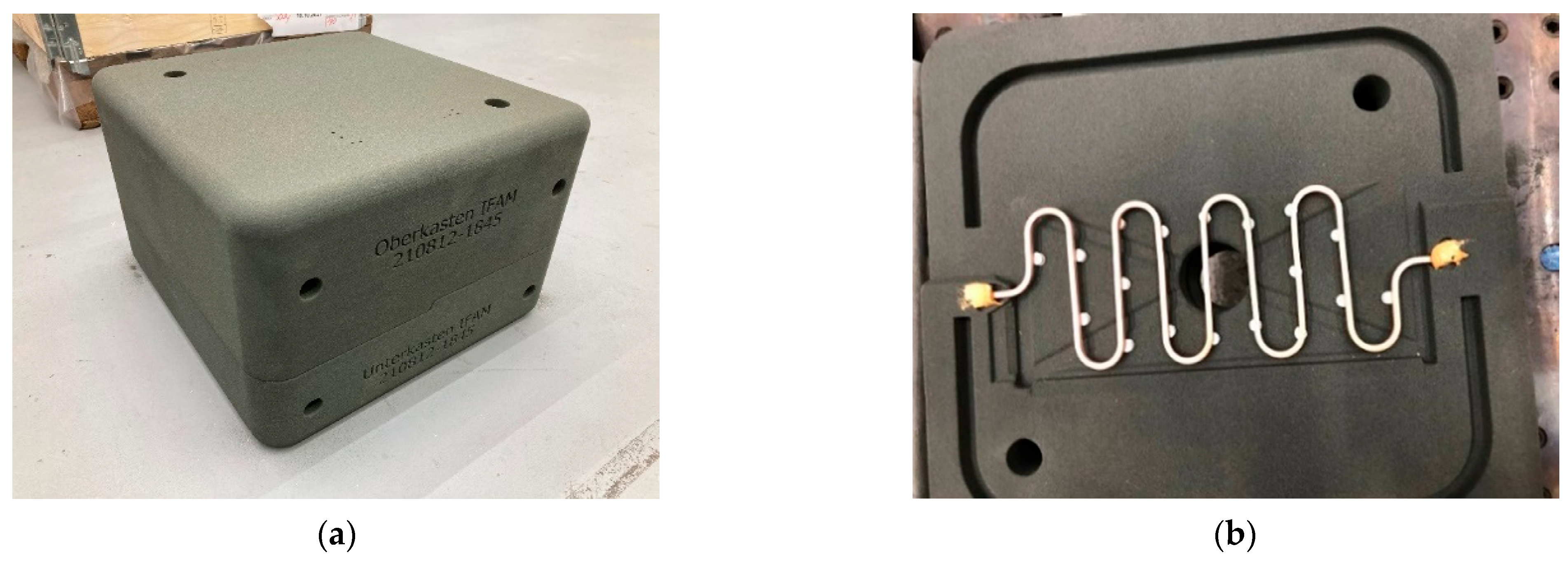
Figure 2 shows a sand core package with dimensions of approx. 400 × 400 mm and a weight of approx. 15 kg. The core package is constructed in two parts. The positioning of a copper cooling channel to be integrated in the casting is realized by the use of core blocks and thus fixed between the two core package halves. In this way, the castings were produced as symmetrical identical parts, so that two of the manufactured components each represent a closed module housing. The castings were produced on a low-pressure casting system within the Fraunhofer Center Wolfsburg at the Open Hybrid LabFactory.
By embedding square copper tubes with external dimensions of 4 × 4 mm and a wall thickness of 0.5 mm, it was possible to provide active cooling close to the contour, directly in the floor or ceiling panel. Copper was chosen as the material for the tempering structures due to its superior thermal conductivity. The rod material was hand-formed into the meandering shape and cleaned with a solvent and sandblasted for better bonding before casting.
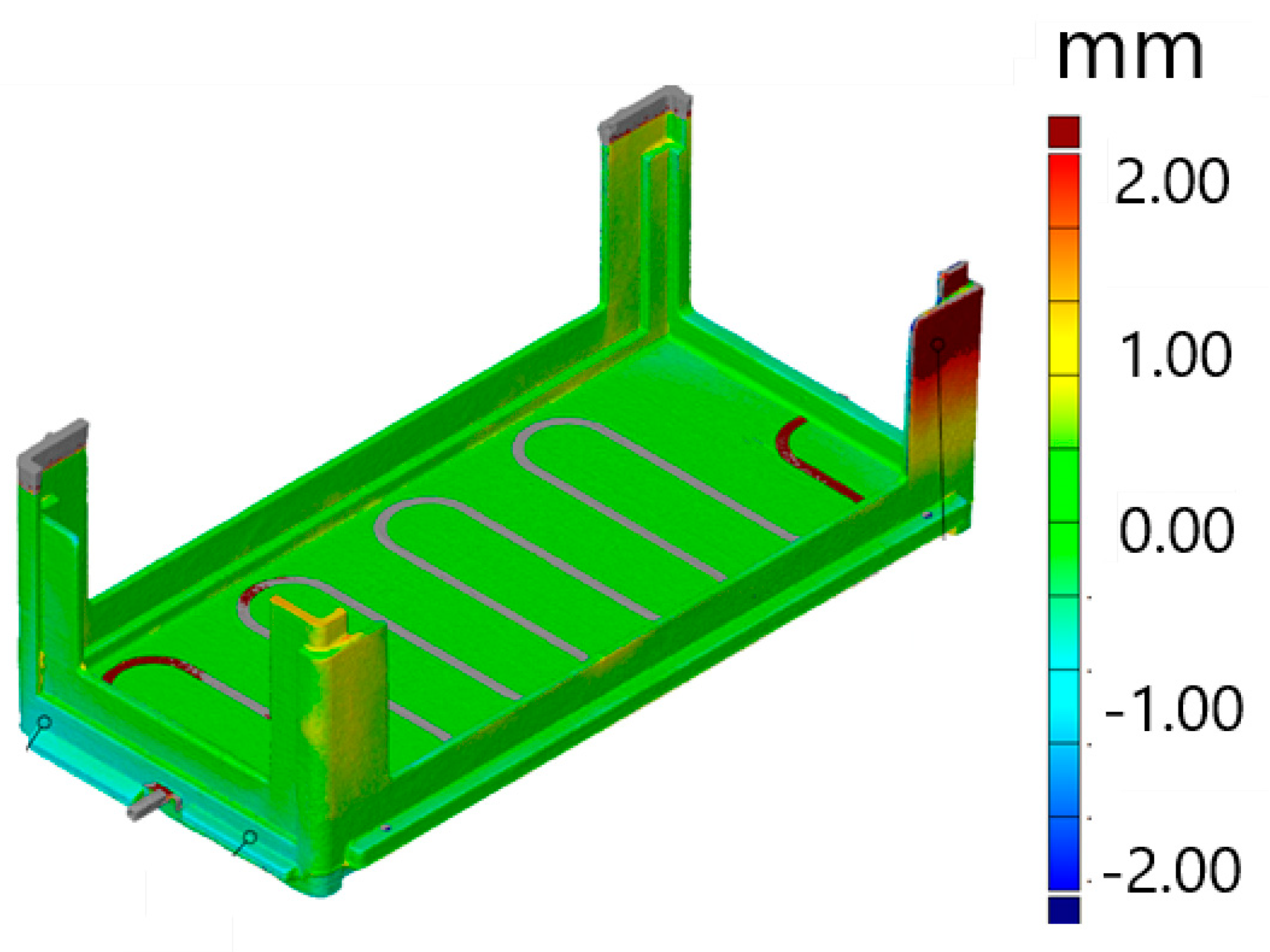
To investigate the dimensional accuracy of the castings and the fit of the upper and lower halves, a scan was performed using fringe light projection. Figure 3 shows the three-dimensional measurement of a finished cast component. Good dimensional accuracy of the internal geometry was achieved. The 2.44 mm deformation of a housing leg shown here, which is due to the mechanical demolding process, was corrected by mechanical straightening. The castings were designed in such a way that, apart from the removal of gates and overflows at the upright corners of the housing half, no mechanical finishing is required. This also takes into account the basic concept of resource-saving production and the use of this battery module.
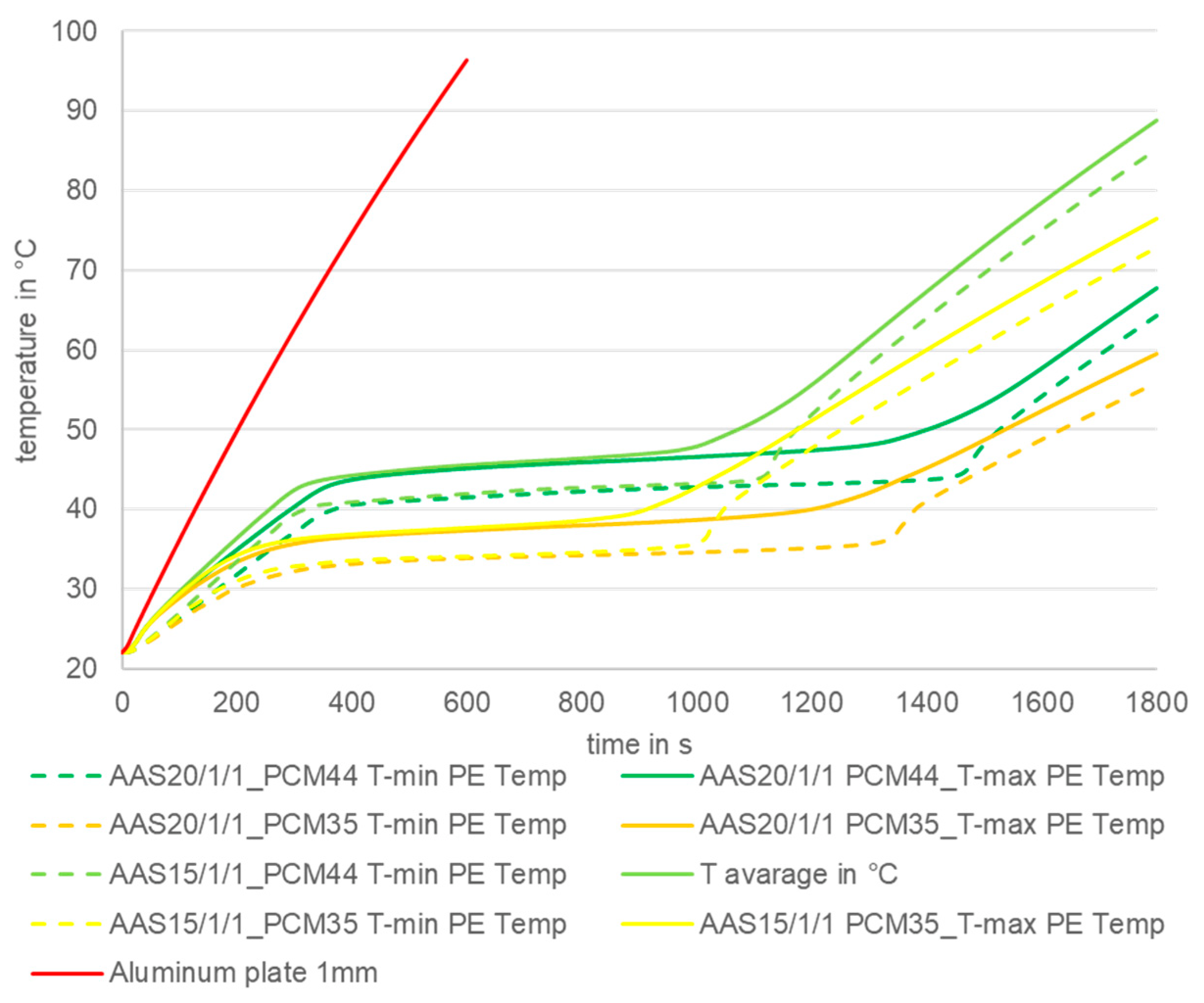
For the thermal investigations, the maximum temperature vs. time curves have been simulated for different PCM melting temperatures and sandwich thicknesses, see Figure 4. The red curve represents the temperature increase for the PE placed on a 1 mm aluminum sheet. The nomenclature of the aluminum foam sandwiches (AAS, German: Aluminium-Schaum mit Aluminium-Decklage) is the total thickness as the first number, followed by the cover sheet thicknesses.
From the simulation results, it can be concluded that all sandwich structures with PCM setups result in significantly lower maximum temperatures than the reference 1 mm aluminum plate, due to the thermal inertia. For the scenario of a 60 s applied load and a sandwich thickness of 15 mm, the maximum temperature for PCM with a melting area around 35 °C (PCM35) could be decreased by 61%, and for PCM with a melting range of 44 °C (PCM44) it could be decreased by 53%. Moreover, the graph shows that for the given scenario, PCM35 results in lower temperatures than PCM44. Furthermore, it can be seen that the total sandwich thickness has a very small influence on the maximum temperature, before reaching the heat storage capacity of the composite. A thicker sandwich, consequently containing a higher amount of PCM, shifts the temperature rise after the PCM melting towards longer times. The temperature differences between maximum and minimum are below 5 K, which characterizes the high thermal conductivity and thus the rapid thermal loading of the composite.
Based on these results a setup of AAS15/1/1, which means a sandwich with a total thickness of 15 mm and 1 mm-thick cover sheets, infiltration with PCM35 was chosen for the battery module.
Figure 5 shows the simulation result for the operating module load case. The maximum cell temperature remains below 38 °C, and the maximum PE temperature does not exceed 50 °C. Further thermal design investigations that were examined on the fire behavior of the used materials and their impact on thermal runway/propagation will be part of additional publications.
For the front lid sandwich structures made of closed cell aluminum foam, covered aluminum sheets were produced via a powder metallurgical foaming route. The first setup of AAS15/1/1 for the base plate and a second setup of AAS25/2/2 for the bumper, joined vertically on the base plate, were manufactured. After placing inserts for joining the lid with the module frames and sealing the sandwich along the edges, PCM was infiltrated with pressure support. The closed cell foam, which consists of cell rods as well as cell walls, has micro and macro cracks in its wall structure, enabling the foam to be infiltrated with the PCM. Finally, the infiltration ports were sealed.
To meet the bonding requirements, as explained in chapter 2, an adhesive bonding concept was developed, which is shown in Figure 6. For this purpose, a temperature-resistant adhesive tape (DuploCOLL® 930 F, Lohmann, Neuwied, Germany, temperature range −40 to 125 °C) was applied all around the pure resin sides of the CFRP side walls over a width of 11 mm. The side walls are positioned relative to the pouch cell package (Figure 6, top left) and, using two pressure plates, the pouch cell package is subsequently compressed (top center) to such an extent that it can be inserted into the first half of the housing (top right). The second half of the housing is positioned in a next step (bottom left and center). Once compression is complete, which causes the pouch cell package to expand and exerts the necessary joining pressure, the adhesive tape is pressed against the inner adhesive flanges of the housing parts, thus joining the two housing parts via the two side walls (Figure 6, bottom right).
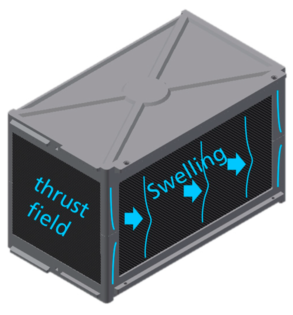
On the rear-end face of the already joined battery module housing, a further CFRP lightweight panel was connected from the outside onto the adhesive flange, also using the above-mentioned adhesive tape. Among other things, this wall also acts as a shear field to limit the bending up of the housing struts under the load case “internal pressure as a result of swelling of the punched cell stack” (Figure 7).
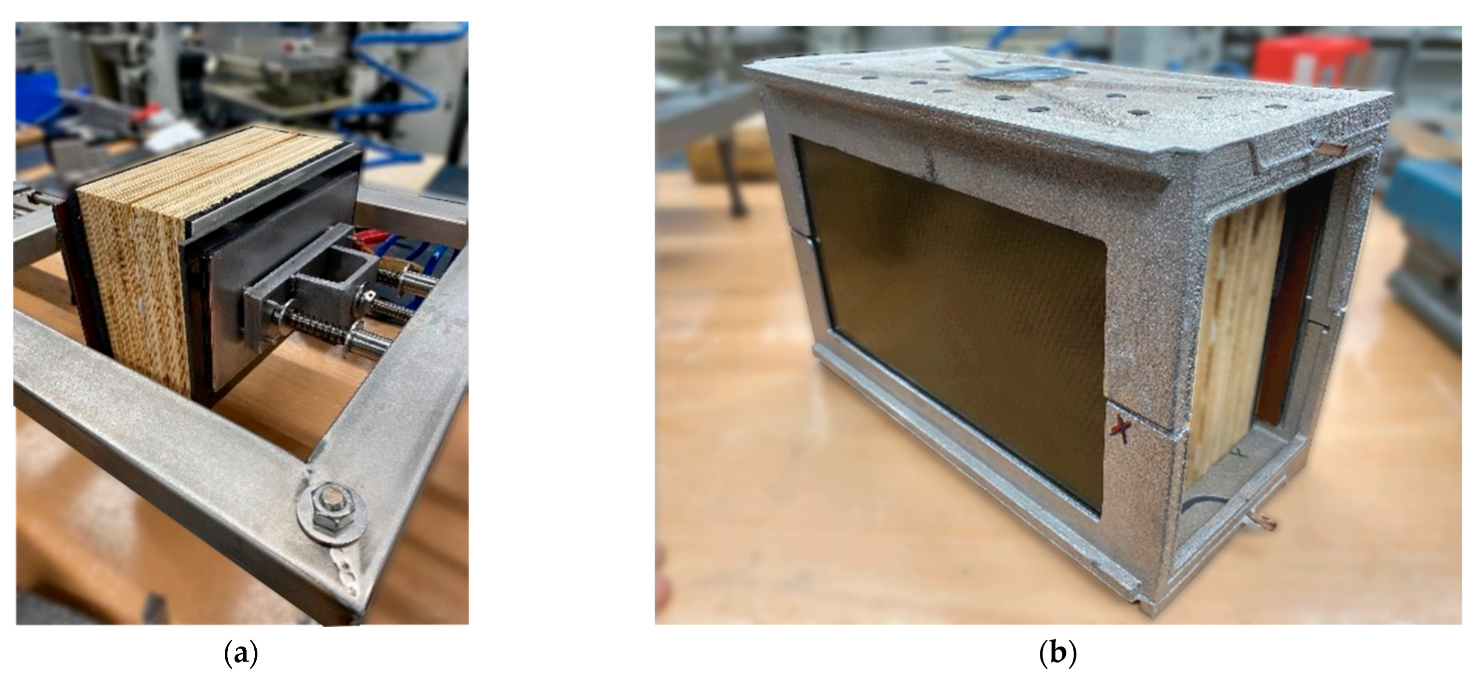
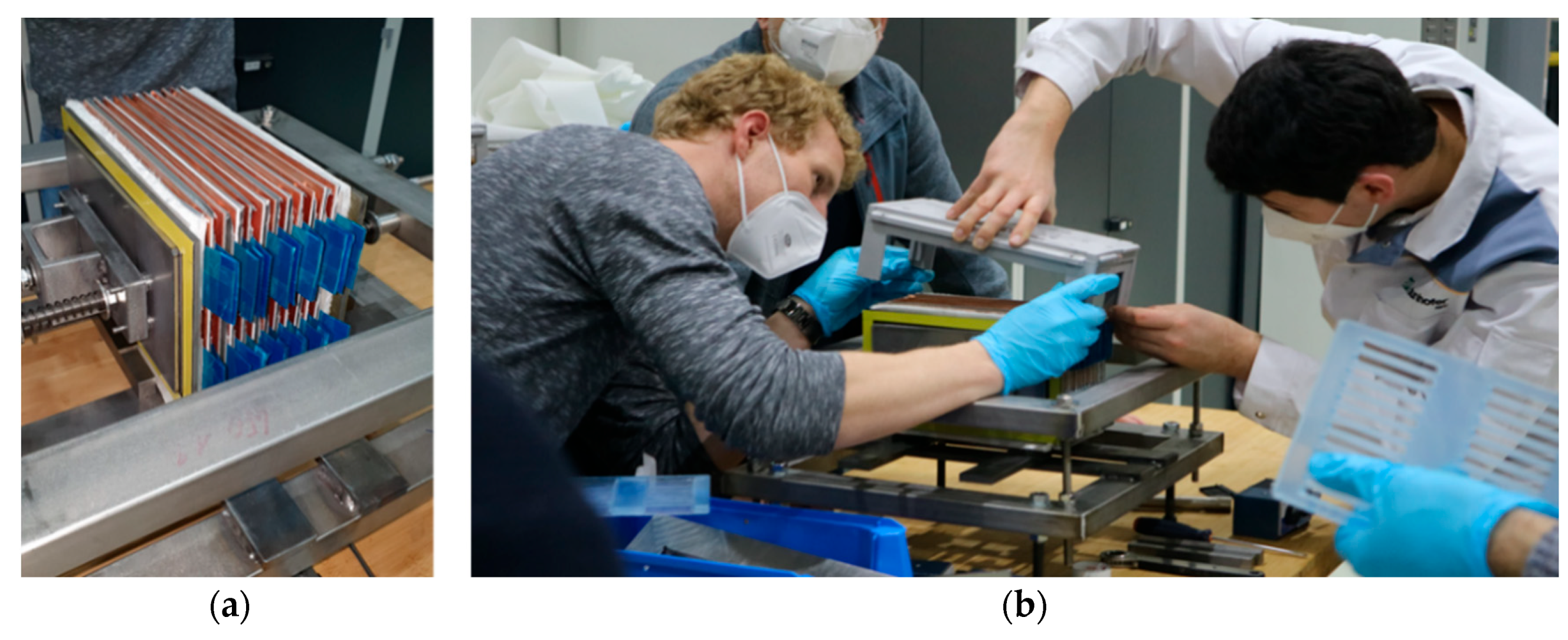
The device used to join the side panels with the two battery module housing parts is shown in Figure 8 on the left. A joined battery module is shown in the figure on the right. Figure 9 shows the assembly process of the demonstrator modules. The finally assembled battery module can be seen in Figure 10.
Dismantling of the lateral lightweight walls (e.g., at the end of use of the battery module to remove the pouch cells) can be carried out with the above-mentioned device. Since adhesive tapes generally have only limited adhesion, they can be removed from the substrates by means of peeling stresses in Mode I at a sufficiently low removal speed and, if necessary, with temperature support. In the case of the tape-joined CFRP lightweight sidewalls of the battery module housing, the device developed for joining the walls also enables a sufficiently high head tensile load to be applied, which locally causes a peeling stress on the tape so that it detaches from one of the joining partners and the FRP sheets can thus be separated from the cast Al structure again. The lightweight CFRP panel joined from the outside on the face side must first be dismantled by being levered out.

4. Discussion

Vision and Further Goals

The presented battery module (Figure 10) forms the basis for a novel, modular design for vehicle batteries. The design makes it possible to dispense with an additional battery box in the future as all relevant functions are integrated within each individual module. In addition, the new battery module was designed to withstand structural loads. This brings several benefits in terms of CE and the sustainability of future BEV design. During early life-cycle phases, especially production, the number of parts as well as the number of resources used can be reduced. Later on, users of the vehicle can flexibly configure the battery capacity according to their individual needs in order to scale down unnecessary weight or material consumption and increase efficiency.
A potential application of this flexible and modular battery design is for vehicle classes such as light commercial vehicles, people movers, or conventional buses/minibuses that regularly travel on fixed routes with a plannable necessary range. The modular design allows for the battery to be efficiently tailored to the size of the vehicle in question. If the range requirement changes in the course of the vehicle life cycle, battery modules can be added or removed with little effort thanks to the modular design. This enables the efficient utilization of resources.
In future investigations, the modular battery will be optimized with respect to the car’s critical body load cases using finite elements methods. Furthermore, subsequent work shall consider alternative bonding and debonding methods for the battery module’s constituents to support different CE strategies with regard to extending the respective life cycles of these parts. As a rather visionary idea, it might be interesting to analyze the integration of the battery module concept into a swappable battery concept that is still pursued by several industry players from China (see e.g., [12,13,14]). Following a product-service system approach, providers could offer a business model that allows users to configure their vehicle with a battery capacity sufficient for their daily needs and to flexibly rent additional battery modules at a swapping station when needed, e.g., for a long-distance ride.

5. Conclusions

The developed module design shows significant potential for further follow-up of the concept. Some promising technologies were summarized based on the demonstrator presented and show potential for future use in battery module housings. This is especially the case for the basic design approach, which allows for easy module assembly and disassembly.
The technologies demonstrated on the demonstrator, such as “debonding-on-demand” CFRP for applications with high fire protection requirements as well as EMC protection requirements, passive cooling using a PCM foam, the use and design of an aluminum cast housing without additional post-processing, and the considered suitability for the re-use of the individual parts, entail interesting approaches.
In further investigations, open questions still need to be addressed with regard to actual achievable loads (e.g., crash), the vehicle integration of module packages, and the design of the interfaces between the individual modules for electrical contact and media supply. Furthermore, there is still the potential for a weight reduction in the housing through, for example, an optimized design or adaptations in the casting process.

Author Contributions

Conceptualization, methodology, formal analysis, resources, and writing—original draft preparation, review, and editing: S.S., J.C., R.v.d.A., O.K., R.S., D.L., M.J.W. and L.B. All authors have read and agreed to the published version of the manuscript.

Funding

This research was funded by German Federal Ministry of Education and Research (BMBF), grant number L1FHG42421; the authors are thankful.

Institutional Review Board Statement

Not applicable.

Informed Consent Statement

Not applicable.

Data Availability Statement

Not applicable.

Conflicts of Interest

The authors declare no conflict of interest.

References

  1. König, A.; Nicoletti, L.; Schröder, D.; Wolff, S.; Waclaw, A.; Lienkamp, M. An Overview of Parameter and Cost for Battery Electric Vehicles. Electr. Veh. J. 2021, 12, 21. [Google Scholar] [CrossRef]
  2. McGuckin, N.; Fucci, A. Summary of Travel Trends: 2017 National Household Travel Survey; Daniel, E., Jenkins, P.E., Eds.; Federal Highway Administration: Washington, DC, USA; US Department of Transportation: Washington, DC, USA, 2018; p. 20590. Available online: https://nhts.ornl.gov/assets/2017_nhts_summary_travel_trends.pdf (accessed on 27 April 2022).
  3. Bastin, Z.; Bhattacharya, S.; Kumar, A. International Electric-Vehicle Consumer Survey, Are Battery Electric Vehicles Here to Stay? Automotive & Industrial. 2019. Available online: https://www.alixpartners.de/media/13453/ap-electric-vehicle-consumer-study-2019.pdf (accessed on 27 April 2022).
  4. Kostorz, N.; Fraedrich, E.; Kagerbauer, M. Usage and User Characteristics—Insights from MOIA, Europe’s Largest Ridepooling Service. Sustainability 2021, 13, 958. [Google Scholar] [CrossRef]
  5. Block, L.; Werner, M.; Mikoschek, M.; Stegmüller, S. Developing Technology Strategies for Flexible Automotive Products and Processes. In Advances in Automotive Production Technology—Theory and Application. ARENA2036; Weißgraeber, P., Heieck, F., Ackermann, C., Eds.; Springer: Berlin/Heidelberg, Germany, 2021. [Google Scholar] [CrossRef]
  6. Füller, K.H.; Schäfer, J.; Zehnpfennig, L.; Budaker, B.; Hossfeld, M.; Keilhoff, D. FlexCar-A Technology Platform Concept for the Future Cyberphysical Vehicle at the Research Campus ARENA2036. In Proceedings of the Werkstoff Plus Auto-9, Tagung für neue Fahrzeug- und Werkstoffkonzepte, Stuttgart, Germany, 20–21 February 2019. [Google Scholar]
  7. Block, L.; Werner, M.; Spindler, H.; Schneider, B. A variability Model for Individual Life Cycle Paths in Life Cycle Engineering. In Proceedings of the FAPC 2022, Future Automotive Production Conference FAPC 2022, Wolfsburg, Germany, 17–18 May 2022; Dröder, E., Herrmann, C., Vietor, T., Eds.; pp. S1–S10. [Google Scholar]
  8. Kirchherr, J.; Denise, R.; Hekkert, M. Conceptualizing the circular economy: An analysis of 114 definitions. Recour. Conserv. Recycl. 2017, 127, 221–232. [Google Scholar] [CrossRef]
  9. Ganesh, S.; Venkatesan, S. Evolution of flexible modular electric vehicle platforms among automotive industry and its influence on battery integration. Int. J. Veh. Struct. Syst. 2021, 13, 361–366. [Google Scholar] [CrossRef]
  10. Mehling, H.; Cabeza, L.F. Heat and Cold Storage with PCM: An Up to Date Introduction into Basics and Applications; Springer: Berlin/Heidelberg, Germany, 2008. [Google Scholar]
  11. Schmerler, R.; Hipke, T.; Drebenstredt, C. SMC-Aluminum lightweight battery case design with switchable temperature control functionality. In Proceedings of the Automotive Circle-Conference for Battery Systems in Car Body Engineering, Bad Nauheim, Germany, 26 October 2021. [Google Scholar]
  12. NIO. Battery Swapping. Available online: https://www.nio.com/blog/current-state-ev-battery-swapping (accessed on 27 April 2022).
  13. CATL Battery Swap Solution. Available online: https://www.catl.com/en/news/856.html (accessed on 27 April 2022).
  14. Geely Battery Swapping Tech. Available online: http://zgh.com/media-center/story/8-reasons-why-geelys-battery-swapping-tech-is-the-future-for-evs/?lang=en (accessed on 27 April 2022).
Figure 1. Exploded CAD view of the developed battery module and its components.
Wevj 13 00177 g001
Figure 2. Core package made of 3D-printed sand, in two parts. (a) Top and bottom box assembled; (b) copper cooling channel positioned in the bottom box with the help of core blocks.
Wevj 13 00177 g002
Figure 3. Three-dimensional measurement of the real components by means of fringe light projection and comparison with the CAD target geometry.
Wevj 13 00177 g003
Figure 4. Simulated temperature curves of aluminum foam sandwiches (AAS) infiltrated with PCM and aluminum plate for the defined thermal PE load case.
Wevj 13 00177 g004
Figure 5. Sectional view of temperature distribution within the module.
Wevj 13 00177 g005
Figure 6. Concept for joining the battery module housing parts.
Wevj 13 00177 g006
Figure 7. Load case “internal pressure as a result of swelling of the punch cell stack during loading”.
Wevj 13 00177 g007
Figure 8. (a) Device for inserting the battery cells into the battery module housing halves and joining them and joined battery module housing. (b) A dummy battery-cell stack made of wooden elements of the same thickness was used for testing.
Wevj 13 00177 g008
Figure 9. Demonstrator assembly: (a) positioning of the cell stack in the joining device; (b) assembly of the module shells.
Wevj 13 00177 g009
Figure 10. Demonstrator of the battery module. Left: rear view with window to provide insight into the module. Right: front view with stacked battery pouch cells and without cover.
Wevj 13 00177 g010
Publisher’s Note: MDPI stays neutral with regard to jurisdictional claims in published maps and institutional affiliations.