Article

A New Hybrid Ant Colony Optimization Based PID of the Direct Torque Control for a Doubly Fed Induction Motor

1
Industrial Technologies and Services Laboratory, Higher School of Technology, Sidi Mohamed Ben Abdellah University, Fez 30000, Morocco
2
Laboratory of Mechanical, Computer, Electronics and Telecommunications, Faculty of Sciences and Technology, Hassan First University, Settat 26000, Morocco
3
Electrical and Electronics Department, Lac Hong University, Bien Hoa 810000, Vietnam
4
Electrical Engineering Department, Faculty of Engineering, Minia University, Minia 61111, Egypt
*
Authors to whom correspondence should be addressed.
World Electr. Veh. J. 2022, 13(5), 78; https://doi.org/10.3390/wevj13050078
Submission received: 10 April 2022 / Revised: 24 April 2022 / Accepted: 26 April 2022 / Published: 29 April 2022

Abstract

:
Due to its advantages, the Proportional Integral Derivative (PID) controller has been the most widely used controller in the industrial sector. It allows linear systems to have good performance, but if the system is subjected to physical variation conditions, the system’s behavior becomes non-linear, in which case the PID controller is insufficient. The use of the PID controller for speed control in rotating machines, such as the doubly fed induction motor (DFIM) is widely used, but the non-linearity of the machine parameters allows for undesirable behaviors, resulting in overshoots and torque ripples. For this reason, several techniques have been adopted to increase the DTC’s robustness. One finds the integration of artificial intelligence as optimization algorithms. These algorithms are used to generate gains close to the optimum, converging the behavior of the DFIM to its optimum. In this work, an Ant Colony Optimization (ACO) algorithm was proposed to adjust the PID controller gains of the DTC control to control the DFIM, using a combined weighting cost function, to obtain efficient torque and speed control. This paper presents a new hybrid structure resulting from the intelligent ACO-DTC control implemented on Matlab-Simulink. The performance results extracted from the simulation showed the effectiveness of the intelligent ACO-DTC control, which provides satisfactory performance in terms of rapidity, stability, precision, and torque ripples compared to the conventional DTC.

1. Introduction

Since the dawn of industrialization, researchers have been confronted with the control of electrical machines at variable speeds. This is because electric drives are becoming more demanding of efficiency, reliability, and reduced cost [1,2,3]. In the 19th century, this problem was solved with direct current motors, but these machines can not be used in high power ranges, or in corrosive environments, and there is also maintenance required by the commutator [4,5]. Therefore, these constraints have directed research in the field of variable speed towards AC machines, and more particularly towards asynchronous machines. These have many advantages: Low production costs, relatively simple manufacturing, overload support, higher rotation speed, and no need for continual maintenance distinguish these products from their competitors [6]. The asynchronous machine, on the other hand, has a significant disadvantage, the dynamic model structure is highly nonlinear and has a high degree of coupling existence between flux and torque, which makes it more difficult to control [7]. Among the most important developments in the field of high-power drives is the introduction of a new solution by using alternating motors operating in a somewhat special mode, namely the Doubly-Fed-Induction-Motor (DFIM) with a wound rotor, It can be fed by two different voltage sources, on both sides of DFIM. There is a growing interest in this machine. Due to the flexibility degrees it provides due to the accessibility of its rotor and hence the possibility of powering it by a converter on both the rotor and stator sides, as well as the extension of the speed range, it has generated considerable interest [8].
The association of the asynchronous machine and the use of a dual power supply for static converters allows for the implementation of a variety of control schemes [9]. The first control that was introduced in the industry was the Scalar Control (SC), widely used for its simplicity of implementation and its reduced cost. This control has the virtue of being straightforward and straightforward to implement. Its big drawback is the static and dynamic inaccuracy of torque control at low speed, because of the resistive elements which are no longer negligible [10], it has occupied a large part of industrial applications at variable speeds. However, the requests for more efficient applications have opened the way for researchers to develop appropriate controls that meet industrial requirements [9,10].
Several theoretical studies have been carried out on the DFIM to correctly control its behavior. The first controls that exist in the literature that have been carried out on the DFIM are the Flux Oriented Controls (FOC). The main objective of this control lies in transforming the behavior of the AC machines into the behavior of DC machines, i.e., to have a decoupling between the flux and the torque. The first type is called Direct Flux Oriented Control (DFOC), which requires direct measurement of flux, but in this case, a sensor must be placed in the machine air gap to make the measurement. This generates harmonics in the flux due to the mechanical vibration of the machine and the temperature caused by the joule losses [11], which has led researchers to find another solution to avoid using a flux sensor, which is known as Indirect Flux Oriented Control (IFOC), However, DFOC and IFOC controls are very sensitive to the parametric variations of the machine because the control in DFOC and IFOC is performed by more than six PID controllers. It is well known that PID controllers present great robustness in linear systems, but they present poor efficiency in non-linear or variable parameter systems [4,12]. This is the fact that led Takahashi, Noguchi, and Depenbrock to find such efficient and less expensive controls. These efforts were rewarded with the introduction of the Direct Torque Control (DTC) [7,8], which was essentially designed to compete with previous controls, has a PI speed controller, and does not require a Pulse Width Modulation (PWM) generator. This leads to a much more interesting dynamic response in comparison to the FOC technique [1,10,12]. With these advantages, the DTC technique, known disadvantages that reduce their robustness, the variation of stator and rotor resistances, low-speed operation, and the use of hysteresis comparators that leads to variable frequency operation, will make the harmonic content of the different signals rich in harmonics which will cause mechanical resonances causing vibrations and audible noise, which leads to early aging of the machine [1,13].
A PI regulator is utilized to control the speed of the DTC, as is the case with most modern devices. Industrial applications utilizing the PI or PID control systems are numerous and diverse. These are linear control approaches, which have the advantage of being simple to apply and simple to synthesize because of their linear structure. Its uses will be ineffective, particularly if the systems to be regulated have complicated and nonlinear features [14], and because of the well-known characteristics of the PID regulator, which are not resilient when the process is nonlinear and multidimensional, and because its gains are dependent on machine parameters that are not constant owing to physical restrictions [15]. For this reason, several research studies have been conducted to tackle the disadvantages of the PID regulator in variable parameter systems. Intelligent algorithms of optimization, for example, autotuning [16], Particle Swarm Optimization (PSO) [17], Genetic Algorithm (GA) [18,19,20], Fuzzy Logic [21], Evolutionary Programming (EP) [22], and Future Search Algorithm (FSA) [23], have been applied to optimize the parameters of the PID controller. The Ant Colony Optimization (ACO) algorithm is an evolutionary heuristic algorithm based on observations of real ants’ behavior in wild foraging. It was initially proposed by Marco Dorigo in 1992. ACO is used as the optimization engine and a process-based crop growth model which presents better results in [24], In [25] the objective of ACO is to obtain classification rules from data, The rule lists discovered by ACO are smaller compared to data mining algorithms. In [26] an analysis of communication policies by using ACO, specifically demonstrated that the relative effectiveness of alternative communication policies changes as the ACO cost functions increase or decrease. In [27] the results demonstrate the applicability of ACO, as well as the fact that parameter values allow for more diversification of the search result in a more accurate diagnostic result, and path planning in the fault diagnosis of the Inverted-Pendulum System. Furthermore, ACO has been frequently utilized to fine-tune the parameters of PID controllers. T. Sakthivel et al. [28], ACO was presented in order to find optimal parameters of the PI regulator. The controller had been employed in a Shunt Active Power Filter (SAPF) to enhance its dynamic characteristics, which provides faster convergence in comparison to both Genetic Algorithm (GA) and Differential Evolution (DE) algorithms. Rajasekar et al. [29], when using an ACO to regulate a variable speed induction motor, the speed response curve with the ACO optimized regulator parameters provides good responses at all operating conditions when compared to that of a standard PI regulator, which was previously introduced. Nal et al. [30] determined that both ACO and GA algorithms were capable of tuning the PID regulators parameters in the pressure process with great performance. Numerical simulations of a nonlinear chaotic model with improved PID control are shown in [31], where the effectiveness and efficiency of the ACO technique are demonstrated. developed and presented ACO for the purpose of designing a PID controller for a nonlinear chaotic model. Reference [32] describes a new control technique for DFIM that involves adjusting the parameters of the PID speed regulator using a genetic algorithm (GA) of DTC control applied at the stator while the rotor is supplied with 12 V voltage and 5 Hz frequency in order to avoid having mediocre torque ripples. On the other hand, it functions as an induction motor under these conditions, making it unable to benefit from the advantages that DFIM provides, such as overspeed operation [9], and other features. To take advantage of all of the advantages that this machine has to offer, the authors of [33] used the same technique as the authors of [32], but they applied it to both sides of the DFIM instead of just one. There are currently only two studies in the literature that use optimization algorithms to optimize the PID-DTC control applied to DFIM, including [32,33], in this article, ACO is used in the DTC control applied to both sides of a DFIM, and [34,35], use GA for PID controller optimization. It is advantageous to use ACO for a variety of reasons, including the capacity to respond at a faster rate and with no static error in the response speed. In this paper, the work focuses on the analytical study and design of DTC control applied on both sides of DFIM, and the gains of the PID speed regulator are optimized by the ACO algorithm using combined weights of cost functions ITAE, IAE, and ISE in comparison to classical DTC method to show the robustness of the novel proposed smart approach, this study will be evaluated in a Matlab/Simulink environment, the global structure of the proposed hybrid control is presented by the following Figure 1.
The objectives that will be considered in this work are summarized under the following headings:
Optimization of speed and torque tracking in terms of overshoot, rejection time, and response time.
Reduction of torque and fluxes ripples.
Minimization of the stator and rotor currents THDs (Total Harmonic Distortion).
Minimization of the system execution time according to the optimal gains.
To validate these objectives, this article is presented in the following sections: Section 2 is dedicated to the elaboration of the DFIM model in the (α, β) plan. In Section 3, an analytical study of the DTC control will be presented. Section 4, Section 5 and Section 6 is focused on the establishment and design of the ACO algorithm. Section 7 and Section 8 is devoted to the implementation of the ACO-DTC intelligent approach on Matlab-Simulink and the export and interpretation of the simulation results. Section 9 is for discussion and comparison of the proposed ACO-DTC with some works recently published. In the end, a conclusion and a proposal for future research works are adopted for Section 10.

2. Model in Alpha-Beta Frame of the DFIM

The most appropriate model for analyzing the dynamic behavior and the design and implementation of DTC applied to the DFIM, is the two-phases model, expressed by Equations (1)–(5) in (α, β) frame [1,9,12,36,37,38]:
  • Stator Electric equations:
v s α = R s i s α + d ψ s α d t v s β = R s i s β + d ψ s β d t
  • Rotor Electric equations:
v r α = R r i s α + d ψ r α d t + ω m ψ r β v r β = R r i r β + d ψ r β d t ω m ψ r α
  • Stator Magnetic equations:
ψ s α = L s i s α + L m i r α ψ s β = L s i s β + L m i r β
  • Rotor Magnetic equations:
ψ r α = L r i r α + L m i s α ψ r β = L r i r β + L m i s β
  • Mechanical equations
T e m = p · ψ s α i s β ψ s β i s α j d d t + f = T e m T r

3. Analytical Study of DTC

The DTC control theory is predicated on the direct determination of the frequency of the control pulses given to the voltage inverters switches. This is achieved to keep the electromagnetic torque, the rotor, and stator fluxes within the predefined hysteresis bands. Using this strategy, one can assure that there is no coupling between the fluxes and the torque control. Using a voltage inverter, you can enable seven different positions in the phase plane, which corresponds to eight different voltage vector sequences at the inverters’ outputs [1,39].
The DTC control’s primary function is to regulate the electromagnetic torque and flux produced by the DFIM without having measurements of these quantities. However, they are calculated based on measurements of the machine’s stator and rotor currents, respectively.
In the fixed reference (α, β) attached to the stator, the rotor and stator fluxes are estimated and expressed by Equations (6) and (7) [8,9,40]:
ψ s α = V s α R s I s α d t ψ s β = V s β R s I s β d t
ψ r α = V r α R r I r α d t ψ s β = V r β R r I r β d t
The voltages are connected to the commands (Sa, Sb, Sc) of the inverter switches and the Udcs and Udcr DC voltages that supply these converters and are expressed as follows:
V α = U D C 3 2 S a S b S c V β = 3 U D C 3 S b S c
Estimated flux are calculated in the same way, and are described by their modules and positions as follows:
ψ s = ψ s α 2 + ψ s β 2 θ s = tan 1 ψ s β ψ s α
The alpha-beta fluxes have been taken into consideration, by using Equation (10), the electromagnetic torque can be determined:
T e m = p · ψ s α i s β ψ s β i s α

3.1. Flux and Torque Correctors

The stator and rotor fluxes are controlled within a circular crown, and this operation is carried out by two hysteresis comparators with two levels Figure 2a. Furthermore, a hysteresis comparator of three levels regulates the DFIM torque in both rotating directions, allowing it to produce either positive or negative torque depending on the input signal. A hysteresis torque comparator with three levels is depicted in Figure 2b [41].

3.2. Establishment of a Switching Table

In order to develop a control table, it is necessary to show an example of choosing the voltage vector V s or V r that allows both the modulus of the flux and the electromagnetic torque to be increased. We consider that the stator flux vector is in sector 3, the voltage vectors V 2 , V 3 , and V 4 allow us to increase the stator flux modulus and the voltage vectors V 4 , and V 5 allow us to increase the electromagnetic torque.
It is verified that for this position of the flux vector in sector 3, only the voltage V 4 is capable of increasing both the flux and the torque amplitude. Different cases can thus be considered. A null sequence is chosen whenever ΔTem = 0, i.e., when the torque is within its hysteresis band. The reasoning principle applied is the same for the other different cases, whether it is the direction of variation in the stator flux and in the electromagnetic torque, and also wherever the angular position of the stator flux is located. By this method, the following control Table 1 is obtained: What we have explained for the stator is feasible for the rotor [1].

3.3. Syntheses Technique to Calculate the Speed PI Parameters

In DTC, the PI controller is utilized to regulate the speed of the DFIM. When the speed setpoint signal has been compared to the actual observed speed value, it is said to be accomplished. In this case, the comparison error is utilized as an input to the speed PI regulator. The transfer function TF of the process is deduced from the mechanical Equation (5), which presents the speed as a function of the torque which is expressed by 1 f / 1 + s   j f . For the purpose of determining controller gains, the pole placement technique is also used. The speed PI controller schematic block is depicted in Figure 3.
To calculate the gains of the PI regulator, considering Figure 4b after correction in the closed loop of the speed transfer function, it is first necessary to determine the value of the gain G0 by the projection of −45 on the bode diagram of gain through the phase bode diagram as shown in Figure 4b. The measured value of G0 from the bode diagram should be replaced in Equation (12) of Kp, then the value of Kp must be replaced in Equation (12) of Ki, knowing that the value of the time constant t is taken to be equal to 0.1 s. Finally, the values found for Kp and Ki for the speed regulation loop are Kp = 0.776 and Ki = 28.74.
Figure 4. The diagrams of circle Nyquist response (a) and bode responses (b) of Closed Loop Function Transfer (CLFT).
Wevj 13 00078 g004
P I s = T G 0 × τ 1 + 1 T i s = K P + K i 1 s
K P = T G 0 × τ K I = K P 0.1 × J f
where:
T = J f and G 0 = 1 f and τ time constant.
To study the stability of a system, it is necessary to plot the transfer function of the system being studied in a closed loop on the Nyquist diagram. It is necessary that the outline of the circle be found to the left of the coordinate point (−1.0). According to Figure 4a, the contour of the closed-loop system is to the left of the coordinate point (−1.0), so the system is stable.
Figure 5 shows the response of the speed transfer function system after correction. One can say that the speed response shows good follow-up of the setpoint with a very acceptable overshoot and response time.

4. Ant Colony Optimization Algorithm

In order to understand the real behavior of ants, it is necessary to talk about the principle of functioning of real ants and convert the behaviors of ants to mathematical equations, which will then be transformed into an algorithm that allows artificial ants to copy the behaviors of real ants.

4.1. Working Principal

The ACO method is a metaheuristic inspired by ant activity when looking for food. The ants start by moving randomly. Then, they return to the colony (NS) after they have discovered food (ND), marking their way with pheromone [24]. As soon as more ants come across this trail, they are likely to stop their random motions and follow the identified path, strengthening the marking on their way back if the indicated road leads to food. At the same moment, the smallest way will be traversed more frequently, resulting in it being more reinforced and more appealing (positive feedback). The shortest branch selection experiment is illustrated in Figure 6, which shows how the least reinforced branches eventually disappear, prompting all ants to choose the shortest path available.
In the research for food, each ant is regarded as an operator and has the ability to generate solutions based on the decision to use an ant to construct a solution. This is determined by two factors:
  • The visibility factor, also known as the gluttonous force, is denoted by the letter i j , where i j represents the decision that needs to be taken.
  • It is possible to calculate the trace factor as τ i j , where i j is the decision being made and the bigger this value is, the more fascinating it has been in the past to make this decision.
Specifically, the following connection reflects the probability that this element corresponding to a decision i j will be selected.
P i j k τ i j t α η i j t α i e   N i τ i j t α η i j t α 0
The distance between nodes i and j is described by η i j ( t ) (local heuristic information; the ant tends to go as close as possible), and τ i j t is the pheromones concentration deposited on the corresponding arc.   α and β are used to adjust the relative importance given to these two factors.

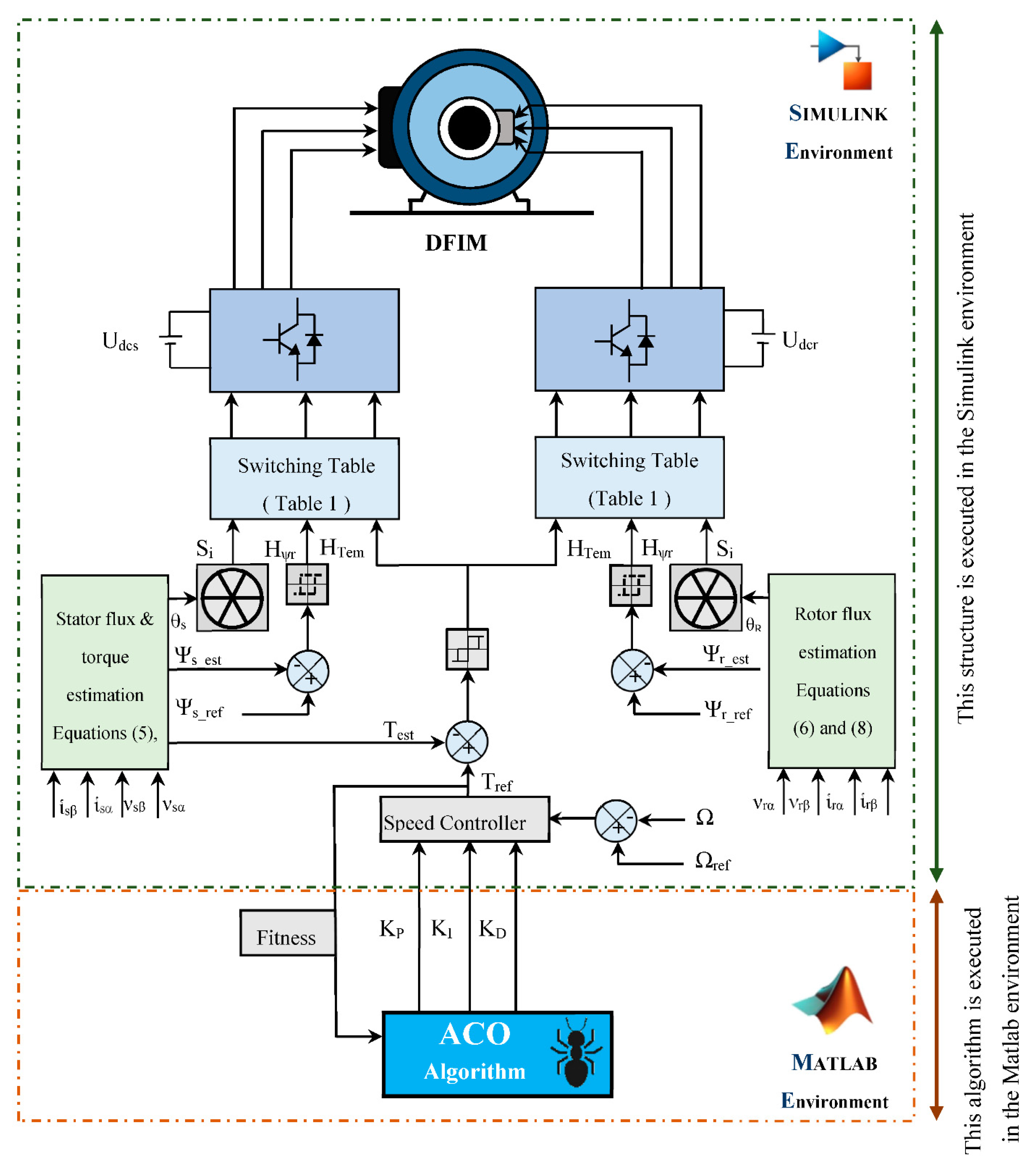
4.2. Design of the Combined ACO with PID Controller

PID optimization strategies with the ACO algorithm have been investigated by several technical researchers. It has been several years since they started using ACO, and they have tried several different techniques to improve its efficiency. Varol et al. [25] have utilized ACO to tune the gains of a speed PID regulator for a second-order system with a variety of objective function options. They discovered a considerable improvement in performance above the traditional tuning procedure. Figure 7 demonstrates the optimization tips of the speed PID regulator by using the ACO block structure.
To describe the working principle to generate the PID gains, it is possible to express this situation as a network problem, as illustrated in Figure 8, in order to answer the challenge of PID regulator design by utilizing the ACO algorithm. We used three different vectors to place all of the values that were related to each parameter (KP, KI, and KD) in order to maximize the efficiency of the algorithm. These vectors could be represented as roads connecting the nests in a graphical representation of the situation. During the tour, each ant is required to travel three nests by selecting the route between the finish node and the start node and then returning to the start node. As indicated in Equation (22), the objective of ACO is to find the most appropriate route between three nests that has the lowest possible objective function (i.e., the least expensive path). That colony of ants places its pheromone at the start of each road. Furthermore, pheromones were updated in accordance with the pheromone updating rule contained within the reinforcement rule when that was completed.
The deposited pheromones are updated on the routes followed by each ant after completing a designated turn according to the following local pheromone update rules (14):
τ i j k = τ k 1 i j + 0.01 θ J
When it comes to the k th iteration, τ i j k is the pheromones intensity between nests i and j .
θ is the coefficient of the concentration pheromone updating.
For the ant’s tour, J   represents the cost function for that tour.
Pheromone pathways pertaining to the optimum tour (15) and worst tour (16) of the ants are updated according to the following expressions, which are considered to represent the general rule of pheromone updating.
τ i j k b e s t = τ k i j b e s t + θ J b s e t
τ i j k w o r s t = τ k i j w o r s t 0.3 θ J w o r s t
When an ant has to make a decision on which direction to take, it must choose the path with the highest pheromone concentration (Jbest), and the paths with the lowest concentration (Jworst) compared to the paths with the highest concentration will be deleted automatically from the history by the use of the expression of Equation (16), i.e., the decision depends on the probability of transition from one location to another. This probability depends on the pheromone concentration. The expression of Equation (17) relates the concentrations in general to the evaporation constant λ.
τ i j k = τ k i j i j λ + τ k i j i j b e s t + τ k i j i j w o r s t
In this equation, λ denotes the evaporation constant [32].

5. Fitness

The selection of the objective functions that will be used to check the appropriateness of each node is a vital phase in the ACO execution process. Many of the studies [13,16] use performance indices as objective functions. According to [15], the researchers make comparisons of three objective functions, such as and Integral Square Error (ISE), Integral Absolute Error (IAE), Integral Time Absolute Error (ITAE), independently and with a weighted combination; this last objective function has proven to be more efficient in terms of performance in comparison to other objective functions; for this purpose, a combined of objective functions with their weights is used in this work to improve the performances of the ACO, thereby improving the overall behavior system. The following are the performance indices that will be used to evaluate the efficiency and robustness to minimize the error rate as much as possible [15]:
I A E = 0 t e t d t
I S E = 0 t e t 2 d t
I T A E = 0 t t · e t d t
F w = ω 1 × I A E + ω 2 × I S E + ω 3 × I T A E
where
F w is the weighted function and e t is the error signal.
ω 1 , ω 2 , and ω 3 are the weights
This controller is employed to reduce the amount of errors e t that are produced, which reduces the value of the specified performance indices, thus minimizing the equivalent value expressed by the nodes, with this minimization the nodes will be formed, the nodes suitability is determined by:
F i t n e s s   V a l u e = 1 F w

6. ACO Parameters

The ACO algorithm and Figure 9 illustrate the stages involved in PID optimization using ACO. This part has 5000 nodes [24], each of which represents one of the parameters of the PID controller. In other ways, a node represents a solution value for the parameters K P , K I , and K D , and each node represents a single solution value. The more nodes that are employed, the more exact the tracks are, but the longer the time it would take for the algorithm to complete its task. Several trials are carried out until the best results are obtained with the smallest number of nodes possible in order to obtain the ACO’s optimal parameter settings. In the course of multiple trials, it was established what the best ACO parameters were ( λ = 0.95 ,   θ = 0.06 ) [24,25].
In order to reach ideal values in a shorter time period, the ACO algorithm’s parameters must be chosen carefully. In this article, a method for validating the two factors (reduced time and optimal values) is developed and discussed.
The parameters of the Ant Colony Optimization algorithm (Algorithm 1) ( V a r P m a x , V a r P m i n , V a r I m a x , V a r I m i n , V a r D m a x , V a r D m i n , and n i t e r ) are necessary to set him to extremely large values. ( V a r P m a x = V a r I m a x = V a r D m a x = 100, V a r P m i n = V a r I m i n = V a r D m i n = −100, n i t e r = 100) to improve the chances of obtaining the optimum values for KP, KI, and KD, however, in this situation, the ACO-DTC only achieves a certain period of time. After this step, the ACO algorithm parameters must also be diminished to those that are closest to the best possible gains previously known, which decreases the number of iterations while reducing the potential running time. The ACO parameters can be seen in Table A1 in Appendix A [24,25].
Algorithm 1. Algorithm of ACO
Begin
Step 1. Initialization of the ACO algorithm parameters ( n _ i t e r ,   N A , α, β, Eva, n_para, n_node, LB, LU).
Create a pheromone matrix and initialize probale solutions to the parameters at random intervals ( K P , K I , K D ) by employing a uniform distribution.
Step 2. Start the DTC and obtain the fitness by using the combined cost functions based on their weights.
Step 3. Identify the node that has the greatest chance of succeeding with probability. using Equation (13).
Step 4. Print the optimal parameters values of the speed PID regulator ( K P , K I , K D ).
The step 2 should be repeated until the maximum number of ants is attained.
Step 5. Make use of the pheromone evaporation calculated by this equation (15), to reinforce the best road and by using Equation (16), we may be able to allow for the forgetfulness of bad decisions.
Step 6. Equation (17) should be used to update the pheromone globally in accordance with the optimal solutions established in Step 5.Step 2 should be repeated as many times as necessary until the maximum number of iterations has been achieved.
Step 7. Choose the best road expressed by the optimal PID gains which is can be concentrated by the maximum pheromone.
End

7. Simulation Procedure and Interpretation

Figure 10 depicts the system structure of the ACO-DTC-DFIM, on which part of the system, such as the control and the inverter with the machine is implemented on Simulink and the algorithmic part is executed on Matlab, i.e., the optimal gains of the regulator are generated on Matlab and then the control is executed with the gains generate on Matlab. The gains values of the speed PID regulator optimized on the basis of the ACO are all within the variation ranges that can be seen in Table 2, and the global system structure is configured also with the required parameters listed in Table A1 and Table A2 of Appendix A and subjected to speed and torque references.
The results of numerical simulation for the two approaches (ACO-DTC and conventional DTC) were put through their paces utilizing a 1.5 kW DFIM along with the following steps:
  • The speed reference starts with a step of 78.5 rad/s lasting 0.5 s.
  • The reference speed abruptly drops to the nominal speed of 157 rad/s, the equivalent of 1500 rpm, which lasts for 1 s.
  • The reference speed drops progressively with a slope of −157 rad/s until the rotation comes to a complete stop. This phase lasts 0.25 s.
  • After the complete stop of rotation, the machine changes the direction of rotation, which is indicated by the negative values of speed.
  • A progressive increase in the reverse direction of a slope of −157 rad/s until reaching the speed of −157 rad/s. This speed remains constant between 2.5 s and 3.5 s.
  • After 157 rad/s, the speed suddenly drops to −78.5 rad/s from 3.5 s to 4 s and the test cycle is completed.
  • In parallel with the reference speed, a variable load torque is applied at instants of 0.75 s and 2.75 s.
  • A load torque of 10 Nm, which implies a nominal load of a 1.5 Kw machine, is applied between 0.75 s and 1.25 s.
  • A nominal load torque of −10 Nm is applied between 2.75 s and 3.25 s. The choice of this negative value is made to follow the direction of rotation of the machine in the reverse direction.
The all parameters of the system are initially configured by:
  • The sampling frequency: fs = 10 kHz.
  • Hysteresis bands widths: ΔTem = ±0.01 Nm, ΔΨs = ΔΨr = ±0.001 Wb.
  • Application of a nominal loads TL = 10 Nm and TL = −10 Nm at t = 0.75 s. and at t = 2.75 s respectively.

Results and Interpretation

The suggested novel intelligent strategy ACO-DTC is examined using Matlab-Simulink working under a range of different conditions to determine its effectiveness. The optimum values for the parameters that were considered for the classical PID controller without optimization were calculated by the synthesis technique presented previously in Section 3.3 and the optimum gains were determined by using the ACO algorithm. The gains of the PID obtained by classic way and using the ACO algorithm are presented in Table 3.
The results of the simulation are presented by the following figures:
  • Figure 11, Figure 12, Figure 13, Figure 14, Figure 15, Figure 16, Figure 17 represent the performances of the DFIM, when the DFIM functions at a speed step of 78.5 rad/s and then instantaneously increases to 157 rad/s and then along a linear slope the speed decreases to −157 rad/s and then instantaneously increases to −78 rad/s, the motor during its functioning according to the speed characteristic i is subjected to torques of 10 Nm and −10 Nm applied at time t = 0.75 s and time t = 2.75 s.
  • It is illustrated in Figure 11a–c that the motor has a smooth response to changes in load, even when the load changes suddenly. After 0.75 s, the motor rotates at speeds of 78.5 rad/s and 157 rad/s with a starting load of 0 Nm and an increase in load to 10 Nm after 0.75 s, the motor is considered to be in operation. The responses of the two controls show a complete tracking of the speed reference, showing remarkable differences. This response shows the improvement of the speed characteristic by the intelligent ACO-DTC approach compared to classic DTC, the overshoot is globally removed in the case of using ACO-DTC, the classic DTC presents 13.45 rad/s giving an improvement by 100%, for the response time of the ACO-DTC given ms 25.6 ms and 50.7 ms for the classic DTC, showing 49.5% as an improvement, The rejection time of the ACO-DTC is 15.9 ms, whereas the standard DTC is 92.5 ms, indicating an improvement of 82.81% over the classic DTC. Undershoot of the ACO-DTC given ms was 4.0432 rad/s and 5.0494 rad/s for the classic DTC, indicating a 19.92% improvement.
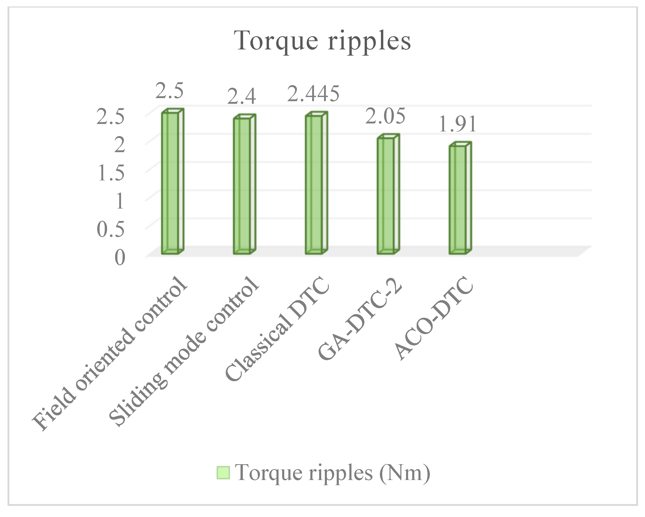
  • The motor torque responses for different strategies are illustrated in Figure 12, From this figure, it is remarked that the response of torque of the proposed ACO-DTC strategy contains fewer ripples compared to the conventional DTC which are presented by 21.88% improvement rates for ACO-DTC compared to DTC (2.445 Nm for DTC and 1.95 Nm for ACO-DTC), the DFIM torque is controlled smoothly, it also has fewer undershoot when there is a sudden load change at 0.75 s and 2.75 s for different strategies.
  • Figure 13 and Figure 14 show the currents characteristics of the stator and rotor DFIM and their THDs. From these figures, it can be seen that the form of the stator and rotor currents deviates from their ideal form expressed by a THD of 7.82% and 11.7%, respectively, which makes the amount of harmonic rich by ripples causing torque ripples of 2.445 Nm for the conventional DTC.
  • Figure 15, Figure 16 show the characteristics of the currents of the stator and rotor and their THDs. The motor currents have fewer ripples with a THD of 4.82% and 7.98%, respectively, which has minimized the number of torque ripples by 1.91 Nm for the ACO-DTC.
  • Figure 17 illustrates the flux responses of the stator and rotor of the classical DTC and ACO-DTC which show improvement in flux amplitudes by 26.66% and 19.45%, respectively.
In general, as compared to a classic DTC, the motor follows its reference torque far more rapidly. Furthermore, the torque is properly regulated even under varying load situations. Figure 10 shows that the motor with the hybrid and suggested DTC, which is based on the ACO algorithm, has a fast response time. It achieves its reference speed rapidly without overshoot and with much less response time, and the speed can really be managed smoothly as possible when there is a sudden modification in different loads; the variations of load from 0 Nm to 10 Nm in 0.75 s and from 0 Nm to −10 Nm in 2.75 s. Table 4 illustrates the overall improvement of the speed performances (response time of 49.5%, overshoot of 100%, rejection time of 82.81%, undershoot of 19.92%), and the torque, fluxes (stator and rotor) ripples of 21.88%, 26.66% and 19.45%, respectively. The currents (stator and rotor) THDs of 38.21% and 32.05%, respectively, were approved by the new intelligent ACO-DTC; with these statistics the ACO-DTC will be the replacement of DTC in the industrial sector. Finally, based on the findings of the entire study, the suggested technique outperforms the standard DTC strategy. The suggested technique may be utilized to manage the motor in a manner that minimizes torque ripples while maintaining good performance.

8. Robustness Test of the ACO-DTC

To verify the robustness of the ACO-DTC control, the machine was subjected to a variable external torque load. The ACO-DTC control showed good follow-up of the setpoint throughout the setpoint with a reduction in torque ripples. On the other hand, the machine can also be subjected to internal disturbances because of the physical conditions, such as the saturation of the machine during its operation, which allows variations in the inductances, whether on the stator or rotor side, so that the machine can be subjected to temperature variations that influence the resistance of the stator and rotor windings of the machine. For this reason, this section is devoted to the robustness test of the ACO-DTC control, in which the machine is subjected to the same conditions mentioned above to test the robustness of the proposed ACO-DTC control.
Figure 18 presents the speed responses of the ACO-DTC control with a variation of the stator (Figure 18a) or rotor (Figure 18b) resistance due to the variation of the temperature and a variation of the stator (Figure 18c) or rotor (Figure 18d) inductance due to the machine saturation. These variations are submitted in the form of an increase or a reduction in the value of the internal parameters of the machine. According to the responses of the speed according to the variation of the stator or rotor resistance and the variation of the stator or rotor inductance, it is very clear to see that the machine speed follows the setpoint correctly throughout the reference setpoint without having overshoot but with a minor variation in the response time, which has no impact on the machine behavior, which means significant robustness of the ACO-DTC control in the face of external or internal disturbances.

9. Discussion and Comparison of the Proposed ACO-DTC with Some Works Recently Published

There are numerous techniques that have been applied to DFIM that may be found in the technical literature, in order to drive the motor at different speed and torque setpoints, we find the FOC control established by [12] because of the abundance of mathematical expressions in the machine’s parameters, this machine is extremely sensitive to dynamic parameter changes, and as a result, it is not resistant to such fluctuations. These results are excellent, with a response time of 0.56 s and torque ripples of 2.5 Nm, respectively, for this method, in [36] the SMC was used, which is characterized by the phenomenon of chattering. The robustness of this technique in terms of torque and speed performances is reduced as a result of this phenomenon, this approach has torque ripples of 2.44 Nm and a response time of 0.19 s; as a result of the limitations of the various controls, the DTC is found to be the most appropriate solution, and among the solutions adopted to increase its robustness are artificial intelligence techniques. The authors in [32] optimized the speed regulator gains of the DTC approach by the GA, in order to have the best behavior of the DFIM in front of the parametric variation of the motor which minimized the torque ripples up to 0.16 Nm. When it comes to the GA-DTC strategy, the control was applied only to the stator side, and the rotor is supplied by a 12 V and 5 Hz source, to achieve the lowest possible torque ripples, this method does not allow for the use of the speed variation band (Overspeed) offered by the DFIM, In [33] the authors proposed the solution to solve the drawback of the strategy proposed by [32] and they improved the DTC control by GA-DTC applied in both sides of the DFIM to take advantage of the machine overspeed, this strategy gave a response time of 0.0304 ms and torque ripple of 2.05 Nm, in our proposed strategy we have followed the same approach proposed by [33] but the algorithm used is ACO for the performance reason explained in the introduction. Table 4 and Table 5 illustrate the performances of different strategies applied to the DFIM.
According to the histograms in Figure 19 and Figure 20, which depict the speed response time histogram and the histogram of torque ripples amplitudes known by each technique, respectively, it is possible from Figure 8 to conclude that the quickest approach is that with the lowest response time, which would be offered up by the proposed method ACO-DTC; the approach with the least ripples from Figure 10 is the proposed method AC-DTC, the GA-DTC-1 control is not taken in the comparison for two reasons, the first, is that the DFIM is controlled only in the stator side which leads to a reduced torque. The second reason is that the machine used 750 W, and to make a legal comparison it is necessary to compare the machines that have the same power. In this work, 1.5 kW is used, and it is the same power used by [12,33,36].

10. Conclusions

The studies in this article are focused on the control of the DFIM behavior by using first the classic DTC, which presents a good following of the references speed and torque, but the speed overshoot and torque ripples remain the major drawbacks of this control; secondly, the improvement of the classic DTC by using a speed PID controller optimized by the ACO algorithm with combined weights of objective functions, such as ITAE, IAE, and ISE. The new combined ACO-DTC has the greatest effect on the DFIM behavior, which resolves the drawbacks of the classic DTC. The global structure is designed on the MATLAB-Simulink. The simulation results showed the ACO-DTC approaches robustness compared to classic DTC. The ACO-DTC control has generated several performance improvements in terms of rapidity, stability, and precision of the machine, which are mentioned as follows:
The response time, rejection time, and overshoot are improved by 49.5%, 82.81%, and 100%, respectively.
The amplitude of the torque ripples is minimized by 21.88%.
The current THDs are reduced by 38.21% and 32.05%, respectively.
The following points are the topics on which the scientific community has chosen to concentrate its efforts:
Performance improvement of DTC control of a DFIM by artificial neuron networks.
Reduction of the effect of the hysteresis comparators by using the ANN controller.

Author Contributions

Conceptualization, S.M., A.D. and N.E.O.; methodology, S.M., N.E.O., M.A.M. and N.V.Q.; software, S.M. and A.D.; validation, S.M., A.D. and N.E.O.; formal analysis, N.V.Q., A.D., N.E.O. and M.A.M.; investigation, S.M., A.D. and M.A.M.; resources, N.V.Q., A.D. and N.E.O.; data curation, S.M., A.D. and M.A.M.; writing—original draft preparation, S.M. and A.D.; writing—review and editing, N.E.O., N.V.Q. and M.A.M.; visualization, S.M. and A.D.; supervision, S.M., N.E.O. and M.A.M.; project administration, N.V.Q. and M.A.M.; funding acquisition, N.V.Q. All authors have read and agreed to the published version of the manuscript.

Funding

This research was funded by Lac Hong University, Vietnam.

Data Availability Statement

The data presented in this study are available upon request from the corresponding authors.

Conflicts of Interest

The authors declare no conflict of interest.

Abbreviations

List of symbols
v s α ,   v s β ,   v r α ,   and   v r β Stator and rotor voltages in (α, β) plan
U d c s   and   U d c r Stator and rotor directs voltages
i s α ,   i s β ,   i r α ,   and   i r β Stator and rotor currents in (α, β) plan
ψ s α ,   ψ s β ,   ψ r α ,   and   ψ r β Stator and rotor fluxes in (α, β) plan
R s ,   R r Stator and rotor resistors
L s ,   L r Stator and rotor inductors
L m Mutual Inductance
p Number of pairs of poles
ω r Rotor angular speed
ω s Stator angular speed
θ s and θ r Stator and Rotor Fluxes position
H t e m Electromagnetic Torque Hysterisis Output
H ψ s   and H ψ r Stator and Rotor Fluxes Hysterisis Output
S i Inverters Sectors
K P , K I   and K D PID gains
Rotation speed
r e f Speed reference
ξ Speed error
τ Time constant
T e m Electromagnetic torque
T r Resistant torque
f Viscous friction coefficient
J Moment of inertia
List of Abbreviations
DFIMDoubly Fed Induction Motor
DTCDirect Torque Control
GA-DTCGenetic Algorithm Direct Torque Control
ACO-DTC Ant Colony Optimization Direct Torque Control
GAGenetic Algorithm
ACOAnt Colony Optimzation
PSOParticle Swarm Optimization
EPEvolutionary Programming
FSAFuture Search Algorithm
PIDProportional Integrator Derivator
DTFCDirect Torque Fuzzy Control
DTNCDirect Torque Neural Control
DTNFCDirect Torque Neural-Fuzzy Control
ANFISAdaptive Neuro-Fuzzy Inference System
IAEIntegral Absolute Error
ISEIntegrale square Error
ITAEIntegral Time Absolute Error
THDTotal Harmonic Distortion
n_eter Iteration Number
n_antAnts Number
EvaEvaporation rate
n_nodeNodes Number
n_parParameters Number

Appendix A

Table A1. The ACO Algorithm parameters.
SymbolsValue
n_eter300
n_ANT30
α0.8
β0.2
Eva0.9
n_par3
n_node5000
Table A2. DFIM parameters.
SymbolsValues (Unit)
Pn1.5 Kw
Vs400 v
Vr130 v
P2
f50 Hz
Rs1.75 Ω
Rr1.68 Ω
Ls0.295 H
Lr0.104 H
M0.165 H
f0.0027 kg·m2/s
J0.001 kg·m2

References

  1. El Ouanjli, N.; Derouich, A.; El Ghzizal, A.; Chebabhi, A.; Taoussi, M.; Bossoufi, B. Direct Torque Control Strategy Based on Fuzzy Logic Controller for a Doubly Fed Induction Motor. In IOP Conference Series: Earth and Environmental Science; IOP Publishing: Bristol, UK, 2018; Volume 161, p. 12004. [Google Scholar]
  2. Mossa, M.A.; Echeikh, H.; Iqbal, A. Enhanced control technique for a sensor-less wind driven doubly fed induction generator for energy conversion purpose. Energy Rep. 2021, 7, 5815–5833. [Google Scholar] [CrossRef]
  3. Mossa, M.A.; Al-Sumaiti, A.S.; Do, T.D.; Diab, A.A.Z. Cost-Effective Predictive Flux Control for a Sensorless Doubly Fed Induction Generator. IEEE Access 2019, 7, 172606–172627. [Google Scholar] [CrossRef]
  4. Mahfoud, S.; Derouich, A.; El Ouanjli, N.; Mohammed, T.; Hanafi, A. Field Oriented Control of Doubly Fed Induction Motor using Speed Sliding Mode Controller. In E3S Web of Conferences; EDP Sciences: Les Ulis, France, 2021; Volume 229, p. 1061. [Google Scholar]
  5. Mossa, M.A.; Bolognani, S. Effective model predictive direct torque control for an induction motor drive. In Proceedings of the IEEE 2016 International Symposium on Power Electronics, Electrical Drives, Automation and Motion (SPEEDAM), Capri, Italy, 22–24 June 2016; pp. 746–754. [Google Scholar] [CrossRef]
  6. Rahman, M.F.; Patterson, D.; Cheok, A.; Betz, R. 30: Motor Drives. In Power Electronics Handbook, 4th ed.; Rashid, M.H., Ed.; Butterworth-Heinemann: Oxford, UK, 2018; pp. 945–1021. [Google Scholar]
  7. Mossa, M.A.; Bolognani, S. Predictive Control for an Induction Motor Drive Based on a Quasi-Linear Model. In Proceedings of the 2018 Twentieth International Middle East Power Systems Conference (MEPCON), Cairo, Egypt, 18–20 December 2018; pp. 242–248. [Google Scholar]
  8. Mossa, M.A.; Bolognani, S. Effective sensorless model predictive direct torque control for a doubly fed induction machine. In Proceedings of the 2017 Nineteenth International Middle East Power Systems Conference (MEPCON), Cairo, Egypt, 19–21 December 2017; pp. 1201–1207. [Google Scholar]
  9. Hassan, A.; Mohamed, Y.S.; El-Sawy, A.; Mossa, M.A. Control of a Wind Driven DFIG Connected to the Grid Based on Field Orientation. Wind Eng. 2011, 35, 127–143. [Google Scholar] [CrossRef]
  10. Mahfoud, S.; Derouich, A.; El Ouanjli, N.; El Mahfoud, M. Enhancement of the Direct Torque Control by using Artificial Neuron Network for a Doubly Fed Induction Motor. Intell. Syst. Appl. 2022, 13, 200060. [Google Scholar] [CrossRef]
  11. Hmidet, A.; Boubaker, O. Real-Time Low-Cost Speed Monitoring and Control of Three-Phase Induction Motor via a Voltage/Frequency Control Approach. Math. Probl. Eng. 2020, 2020, 6913813. [Google Scholar] [CrossRef]
  12. El Ouanjli, N.; Derouich, A.; El Ghzizal, A.; Chebabhi, A.; Taoussi, M. A comparative study between FOC and DTC control of the Doubly Fed Induction Motor (DFIM). In Proceedings of the 2017 International Conference on Electrical and Information Technologies (ICEIT), Rabat, Morocco, 15–18 November 2017; pp. 1–6. [Google Scholar]
  13. Mossa, M.A.; Mohamed, Y.S. Novel Scheme for Improving the Performance of a Wind Driven Doubly Fed Induction Generator during Grid Fault. Wind Eng. 2012, 36, 305–334. [Google Scholar] [CrossRef]
  14. Mossa, M.A.; Echeikh, H.; Quynh, N.V. A Novel Sensorless Predictive Voltage Control for an Induction Motor Drive Based on a Back-Stepping Observer-Experimental Validation. IEEE Access 2021, 9, 11921–11942. [Google Scholar] [CrossRef]
  15. Jayachitra, A.; Vinodha, R. Genetic Algorithm Based PID Controller Tuning Approach for Continuous Stirred Tank Reactor. Adv. Artif. Intell. 2014, 2014, 791230. [Google Scholar] [CrossRef]
  16. Ye, Y.; Yin, C.-B.; Gong, Y.; Zhou, J.-J. Position control of nonlinear hydraulic system using an improved PSO based PID controller. Mech. Syst. Signal Proc. 2017, 83, 241–259. [Google Scholar] [CrossRef]
  17. Feng, H.; Yin, C.-B.; Weng, W.-W.; Ma, W.; Zhou, J.-J.; Jia, W.-H.; Zhang, Z.-L. Robotic excavator trajectory control using an improved GA based PID controller. Mech. Syst. Signal Process. 2018, 105, 153–168. [Google Scholar] [CrossRef]
  18. Mahfoud, S.; Derouich, A.; Iqbal, A.; El Ouanjli, N. ANT-colony optimization-direct torque control for a doubly fed induction motor: An experimental validation. Energy Rep. 2022, 8, 81–98. [Google Scholar] [CrossRef]
  19. Elsisi, M.; Soliman, M.; Aboelela, M.A.S.; Mansour, W. GSA-based design of dual proportional integral load frequency controllers for nonlinear hydrothermal power system. Int. J. Electr. Comput. Energetic Electron. Commun. Eng. 2015, 9, 928–934. [Google Scholar]
  20. Wang, Y.; Jin, Q.; Zhang, R. Improved fuzzy PID controller design using predictive functional control structure. ISA Trans. 2017, 71, 354–363. [Google Scholar] [CrossRef]
  21. Abdo, M.M.; Vali, A.R.; Toloei, A.R.; Arvan, M.R. Stabilization loop of a two axes gimbal system using self-tuning PID type fuzzy controller. ISA Trans. 2014, 53, 591–602. [Google Scholar] [CrossRef]
  22. Hou, Y.-Y. Design and implementation of EP-based PID controller for chaos synchronization of Rikitake circuit systems. ISA Trans. 2017, 70, 260–268. [Google Scholar] [CrossRef] [PubMed]
  23. Elsisi, M.; Soliman, M. Optimal design of robust resilient automatic voltage regulators. ISA Trans. 2021, 108, 257–268. [Google Scholar] [CrossRef] [PubMed]
  24. Dorigo, M.; Birattari, M.; Stutzle, T. Ant colony optimization. IEEE Comput. Intell. Mag. 2006, 1, 28–39. [Google Scholar] [CrossRef]
  25. Parpinelli, R.S.; Lopes, H.; Freitas, A. Data mining with an ant colony optimization algorithm. IEEE Trans. Evol. Comput. 2002, 6, 321–332. [Google Scholar] [CrossRef] [Green Version]
  26. Twomey, C.; Stützle, T.; Dorigo, M.; Manfrin, M.; Birattari, M. An analysis of communication policies for homogeneous multi-colony ACO algorithms. Inf. Sci. 2010, 180, 2390–2404. [Google Scholar] [CrossRef] [Green Version]
  27. Echevarría, L.C.; de Campos Velho, H.F.; Becceneri, J.C.; da Silva Neto, A.J.; Santiago, O.L. The fault diagnosis inverse problem with Ant Colony Optimization and Ant Colony Optimization with dispersion. Appl. Math. Comput. 2014, 227, 687–700. [Google Scholar] [CrossRef]
  28. Sakthivel, A.; Vijayakumar, P.; Senthilkumar, A.; Lakshminarasimman, L.; Paramasivam, S. Experimental investigations on Ant Colony Optimized PI control algorithm for Shunt Active Power Filter to improve Power Quality. Control Eng. Pract. 2015, 42, 153–169. [Google Scholar] [CrossRef]
  29. Rajasekar, N.; Sundaram, K.M. Feedback controller design for variable voltage variable speed induction motor drive via Ant Colony Optimization. Appl. Soft Comput. 2012, 12, 2132–2136. [Google Scholar] [CrossRef]
  30. Ünal, M.; Erdal, H.; Topuz, V. Trajectory tracking performance comparison between genetic algorithm and ant colony optimization for PID controller tuning on pressure process. Comput. Appl. Eng. Educ. 2012, 20, 518–528. [Google Scholar] [CrossRef]
  31. dos Santos Coelho, L.; de Andrade Bernert, D.L. A modified ant colony optimization algorithm based on differential evolution for chaotic synchronization. Expert Syst. Appl. 2010, 37, 4198–4203. [Google Scholar] [CrossRef]
  32. Zemmit, A.; Messalti, S.; Harrag, A.E. A new improved DTC of doubly fed induction machine using GA-based PI controller. Ain Shams Eng. J. 2018, 9, 1877–1885. [Google Scholar] [CrossRef]
  33. Mahfoud, S.; Derouich, A.; El Ouanjli, N.; El Mahfoud, M.; Taoussi, M. A New Strategy-Based PID Controller Optimized by Genetic Algorithm for DTC of the Doubly Fed Induction Motor. Systems 2021, 9, 37. [Google Scholar] [CrossRef]
  34. Chiha, I.; Liouane, N.; Borne, P. Tuning PID controller using multi-objective ant colony optimization. Appl. Comput. Intell. Soft Comput. 2012, 2012, 11. [Google Scholar]
  35. Varol, H.; Bingul, Z. A new PID tuning technique using ant algorithm. In Proceedings of the 2004 American Control Conference, Boston, MA, USA, 30 June–2 July 2004; Volume 3, pp. 2154–2159. [Google Scholar]
  36. Yunus, A.M.S.; Abu-Siada, A.; Mosaad, M.I.; Albalawi, H.; Aljohani, M.; Jin, J.X. Application of SMES Technology in Improving the Performance of a DFIG-WECS Connected to a Weak Grid. IEEE Access 2021, 9, 124541–124548. [Google Scholar] [CrossRef]
  37. Mosaad, M.I.; Abu-Siada, A.; Ismaiel, M.M.; Albalawi, H.; Fahmy, A. Enhancing the Fault Ride-through Capability of a DFIG-WECS Using a High-Temperature Superconducting Coil. Energies 2021, 14, 6319. [Google Scholar] [CrossRef]
  38. Falehi, A.D. Optimal Design and Analysis of NIOFPID-Based Direct Power Control to Strengthen DFIG Power Control. J. Dyn. Syst. Meas. Control 2018, 140, 91001. [Google Scholar] [CrossRef]
  39. Falehi, A.D. Optimal Fractional Order BELBIC to Ameliorate Small Signal Stability of Interconnected Hybrid Power System. Environ. Prog. Sustain. Energy 2019, 38, 13208. [Google Scholar] [CrossRef]
  40. Falehi, A.D. An innovative optimal RPO-FOSMC based on multi-objective grasshopper optimization algorithm for DFIG-based wind turbine to augment MPPT and FRT capabilities. Chaos Solitons Fractals 2020, 130, 109407. [Google Scholar] [CrossRef]
  41. Falehi, A.D. Optimal Power Tracking of DFIG-Based Wind Turbine Using MOGWO-Based Fractional-Order Sliding Mode Controller. J. Sol. Energy Eng. 2019, 142, 31004. [Google Scholar] [CrossRef]
  42. Abderazak, S.; Farid, N. Comparative study between Sliding mode controller and Fuzzy Sliding mode controller in a speed control for doubly fed induction motor. In Proceedings of the 2016 4th International Conference on Control Engineering & Information Technology (CEIT), Hammamet, Tunisia, 16–18 December 2016; pp. 1–6. [Google Scholar]
Figure 1. ACO-DTC control summary structure.
Wevj 13 00078 g001
Figure 2. (a) Torque hysteresis comparators of three-level (b) flux comparators of two-levels.
Wevj 13 00078 g002
Figure 3. The diagram block of speed PI controller.
Wevj 13 00078 g003
Figure 5. The process step response after regulation.
Wevj 13 00078 g005
Figure 6. The selection experiment structure of the smallest branches made by a colony of ants.
Wevj 13 00078 g006
Figure 7. Reduced scheme of the PID-DTC optimized by ACO.
Wevj 13 00078 g007
Figure 8. ACO Graphical Representation for the Purpose of PID Optimization.
Wevj 13 00078 g008
Figure 9. Flowchart of ACO algorithm for PID Controller Optimization.
Wevj 13 00078 g009
Figure 10. Global proposed ACO-DTC structure applied to DFIM.
Wevj 13 00078 g010
Figure 11. Speed responses (ac) of classical DTC and intelligent ACO-DTC.
Wevj 13 00078 g011
Figure 12. Torque responses of classical DTC and intelligent ACO-DTC.
Wevj 13 00078 g012
Figure 13. Stator (a,c) and (b,d) rotor currents responses of classical DTC.
Wevj 13 00078 g013
Figure 14. Stator (a) and rotor (b) THD of classical DTC.
Wevj 13 00078 g014
Figure 15. Stator (a,c) and (b,d) rotor currents responses of intelligent ACO-DTC.
Wevj 13 00078 g015
Figure 16. Stator (a) and rotor (b) THDs of an ACO-DTC.
Wevj 13 00078 g016
Figure 17. Stator (a,c) and rotor (b,d) fluxes responses of DTC and intelligent ACO-DTC.
Wevj 13 00078 g017
Figure 18. Speed response during variation of (a) stator and (b) rotor resistance and (c) stator and (d) rotor inductance of ACO-DTC.
Wevj 13 00078 g018
Figure 19. Various speeds response time of several approaches for DFIM.
Wevj 13 00078 g019
Figure 20. Various torque ripples of several approaches for DFIM.
Wevj 13 00078 g020
Table 1. The sequences of inverters.
Sector Si
H ψ s or   H ψ r H t e m S1S2S3S4S5S6
11v2(110)v3(010)v4(011)v5(001)v6(101)v1(100)
0v7(111)v0(000)v7(111)v0(000)v7(111)v0(000)
−1v6(101)v1(100)v2(110)v3(010)v4(011)v5(001)
01v3(010)v4(011)v5(001)v6(101)v1(100)v2(110)
0v0(000)v7(111)v0(000)v7(111)v0(000)v7(111)
−1v5(001)v6(101)v1(100)v2(110)v3(010)v4(011)
Table 2. The PID parameters band of ACO algorithm.
PID ParametersKPKIKD
Maximum Value10051
Minimum Value000
Table 3. PID controller Parameters under classical DTC and ACO-DTC.
Controller ParametersClassic DTCACO-DTC
KP0.77646.5947
KI28.743.54094
KD00.076549
Table 4. Performances characteristics of the ACO-DTC and DTC.
PerformancesCharacteristicsDTCACO-DTCImprovements %
Response Time (ms)50.725.649.5
Overshoot (rad/s)13.45490100
Rejection Time (ms)92.515.982.81
Undershoot (rad/s)5.04944.043219.92
T Ripples (Nm)2.4451.9121.88
ψ s Ripples (wb)0.058550.0429426.66
ψ r Ripples (wb)0.01220.0098319.45
i s a THD (%)7.824.8238.21
i r a THD (%)11.77.9832.05
Table 5. Comparison between the proposed ACO-DTC and various methods that have just been published.
References of PublicationsTechniquesSpeed Response Time (s)Torque Ripples Amplitude (Nm)Robustness of Techniques
[12]FOC0.562.5Not robust
[42]SMC0.192.4Not robust
-Classical DTC0.05072.445Robust
[32]GA-DTC-10.180.16Robust
[33]GA-DTC-20.03042.05Robust
Proposed techniqueACO-DTC0.02561.91Robust
Publisher’s Note: MDPI stays neutral with regard to jurisdictional claims in published maps and institutional affiliations.

