Article

Parametric Optimisation of a Direct Liquid Cooling–Based Prototype for Electric Vehicles Focused on Pouch-Type Battery Cells

by
Manex Larrañaga-Ezeiza
1,2,*,
Gorka Vertiz Navarro
1,
Igor Galarza Garmendia
1,
Peru Fernandez Arroiabe
2,
Manex Martinez-Aguirre
2 and
Joanes Berasategi Arostegui
2
1
CIDETEC, Basque Research and Technology Alliance (BRTA), Po. Miramón 196, 20014 Donostia-San Sebastián, Spain
2
Mechanical and Industrial Production Department, Faculty of Engineering, Mondragon Unibersitatea, Loramendi 4, 20500 Arrasate-Mondragón, Spain
*
Author to whom correspondence should be addressed.
World Electr. Veh. J. 2022, 13(8), 149; https://doi.org/10.3390/wevj13080149
Submission received: 12 July 2022 / Revised: 27 July 2022 / Accepted: 29 July 2022 / Published: 9 August 2022

Abstract

:
In this work, a numerical optimisation process is applied to improve the fluid dynamical aspect of an innovative direct liquid cooling strategy for lithium-ion–based HEV/EV. First, the thermofluidic numerical model of the battery cell defined by means of CFD computational tools was validated with experimental tests. Then, a comparison between different flow patterns was developed to analyse the influence of the fluid distribution geometry. Finally, a parametric multi-objective optimisation process was implemented arranged by a two-level full factorial design. Considering as input variables the height of the fluid, the number of cooling channels, the number of distributors, and the flow rate, the optimal relationship between the thermal performance of the battery cell, the volumetric energy density of the system, and the power consumption of the strategy was obtained. As a result, the energy density of the system was maximised, and the power consumption was reduced while keeping the cell temperature within the optimal range.

1. Introduction

Aiming to reduce CO2 emissions in densely populated areas, in recent years HEV/EV vehicles have been one of the global benchmark topics in the mobility sector [1]. Considering batteries as the energy source, these technologies enable 100% zero-emission operation. Today, due to their characteristic large density, high discharge capacity, and low maintenance, lithium-ion–based batteries are the reference energy storage technology in the electric vehicle sector.
Although this energy storage technology has high electrical performance, the proper operation of these types of systems is influenced by the temperature at which they operate. The thermal management of these systems is therefore essential. To avoid premature degradation of the energy storage system and prevent risky situations, the optimal working range of lithium-ion batteries is between 15 and 40 °C [2,3], maintaining a cell level temperature uniformity of 0–5 °C. These temperature ranges ensure the best compromise between technical performance and system safety [4].
To control the working temperature of the battery system, in recent years different cooling strategies have been considered. These strategies are generally classified as air cooling, liquid cooling (LC), phase change materials (PCM), heat pipes (HP), and thermoelectric coolers (TEC) [5]. Among these technologies, owing to the thermal conductivity and heat capacity of the implemented fluids, strategies based on liquid cooling (LC) predominate the thermal management of the electric vehicle sector [6]. LC strategies can be divided into two main groups, indirect liquid cooling (ILC) and direct liquid cooling (DLC). Today, ILC is the leading strategy in the field of electric vehicles. However, the fluids used in ILC are electrically conductive, a nature that avoids direct contact with the battery cell. This characteristic decreases the cooling capacity of the strategy compromising the performance of the system [7,8]. Consequently, DLC has been the subject of many studies in recent years [9,10,11,12,13]. DLC strategy uses fluids with high dielectric strength that enable direct contact between the heat generation source (battery cell) and the refrigeration fluid, improving the thermal management efficiency of the system [14].
Recently, some studies have been carried out to analyse the features that can optimise the performance of DLC system. These types of optimisation processes are developed in the numerical environment using multi-physics models to characterise the real working conditions of the system. An example of this type of analysis is the study that Y. Fan et al. [15] developed with a battery module based on 32 cylindrical cells with a DLC strategy. Using a full-immersed casuistry as a reference, the authors analysed the effect of partial cooling by reducing the height of the fluid channel. Results showed that the thermal behaviour of the battery module was worsened by decreasing the height of the fluid channel. However, the authors highlighted that the power consumption of the auxiliary system and the energy density of the battery module were improved. Considering other design parameters, in the development process of a novel direct liquid immersion cooling strategy, M.-Y. Lee et al. [16] analysed the effect of the cell spacing on the system performance. Using a battery module of 14 pouch-type cells of 20 Ah as a reference, the results of the study demonstrated that cell temperatures and pressure drop of the system improves increasing cell spacing. However, the authors mentioned that in a practical scenario, the lowest cell spacing is preferred due to space limitations. Finally, X. Ju et al. [17] performed a geometrical optimisation analysis using a manifold immersion cooling structure for a 51 Ah prismatic battery module. Defining a uniform heat generation on the battery, the structure of the manifold was parametrised to analyse the influence of the fluid line geometry on the thermal and fluid dynamical performance of the strategy. As a result, at the expense of an increment on the pressure drop, a higher and more homogeneous heat transfer coefficient was led on the surface of the battery cells decreasing maximum temperatures and thermal heterogeneities of the system.
Based on the above literature review, we appreciate the importance of analysing the influence of the design parameters to improve the performance of the cooling strategy and, thus, develop a robust, effective, and economical design. To date, there have been few optimisation studies that consider direct liquid cooling strategies as a reference, and the ones based on pouch-type cells, where the thermal characterization becomes more complicated, are in the minority. Furthermore, most of the research has focused on the independent analysis of the influence of the parameters.
Therefore, in this article, a numerical design optimisation of a direct liquid cooling prototype is proposed, defining a specific design of experiments methodology (DoE) to study the interaction of the parameters. The prototype was developed as a partial DLC to decrease the impact of the fluid weight on the energy density of the systems, and it was focused on a large-scale lithium-ion 60 Ah NMC pouch-type cell, a type of cell with high energy to mass ratio and packaging efficiency [18]. To improve the performance of the reference prototype, an optimisation process based on the following steps was undertaken. First, using the numerical CFD environment, the battery cell simulation model was characterised and validated with experimental tests. Then, a comparison between different flow patterns was developed to analyse the influence of the fluid distribution geometry. Finally, a parametric multi-objective optimisation process was implemented to obtain the optimal relationship between the thermal performance of the battery cell, the volumetric energy density of the system, and the power consumption of the strategy.

2. Numerical Model Description

The numerical model is defined to optimize the cell level thermofluidic performance before the scale-up to a module level prototype. To this end, Ansys Fluent 21R2 was used to develop the numerical models. This software enables a coupled analysis, solving the fluid dynamics and the heat transfer considering non-uniform and transient heat generation of the battery cell.

2.1. Physical Model

The partial cooling concept developed in this work is focused on the cooling effect of the cell surface, enabling a direct thermal management of the battery cell. To develop this strategy, a prismatisation component was designed. This component facilitates the internal circulation of the cooling fluid creating a space between the cell contact surface and the component’s internal surface, as is shown in Figure 1.

2.2. Simulation Model Geometry

To replicate the experimental setup, the principal components defined in the simulation model were the following: the battery cell, the fluid, and the clamps (Figure 2). Clamps were implemented because of their influence on the thermal behaviour of the battery cell. These components have almost ten times the mass of the battery tabs and were used to develop the electrical connexion of the tests.
The battery cell implemented in the model is a large-scale 60 Ah NMC pouch-type battery cell. As the battery cell, the dielectric fluid implemented on the model mirrors the characteristics of the commercial dielectric fluid based on mineral oil. The thermal and electrical characteristics of each component are presented in Table 1.

2.3. Battery Modelling

The heat generation of a lithium-ion battery can be expressed by the simplified equation of Newman Qgen = Qirr + Qrev. Where Qgen is the total heat generation, Qirr is the irreversible heat, and Qrev is the reversible heat. The irreversible heat generation, also referred as Joule effect, is represented by the equation Qirr = I2 Rint. Where I is the current (A) and Rint the internal resistance of the cell (Ω), which depends on the temperature (T) and the state of charge (SOC). On the other hand, the reversible heat generation is developed by the insertion and disinsertion of lithium ions into the electrodes (anode and cathode). This generation is based on the electrochemical reactions that take place when discharging and charging the lithium-ion cells, reactions that create a variation in the entropic level of the system. This generation is represented by equation Qrev = IT dEOCV/dT. Where I is the current (A), T is the temperature (K), and dEOCV/dT is the variation of the open circuit voltage with the temperature (V/K).
To characterise the heat generation of the battery cell numerically, an electrothermal model was implemented to mirror the thermal response of the battery cell properly. This model calculates the heat generation of the cell considering the instantaneous temperature (T) and the state of charge (SOC) level. Moreover, this model characterises the influence of the current density increase on the thermal behaviour of the battery cell at high C-rate working conditions.
In this aspect, to characterise the battery cell, the equivalent circuit model (ECM) was selected on the battery module of Ansys Fluent 21R2. This model is widely used because of its simplicity and effectiveness [19]. Using experimental hybrid pulse power characterization (HPPC) testing data, the parameters of the ECM were calculated. This characterization mirrors only the irreversible heat generation of the battery cell. Therefore, to characterize the endothermic behaviour of the battery cell, the entropic factor of the reversible heat generation was implemented by user-defined functions (UDFs). This factor was experimentally characterised analysing the open circuit voltage (OCV) variation with the temperature (dEOCV/dT).
The battery cell heat generation model was validated using experimental voltage and temperature information of a 1C discharge test (Figure 3). The simulation model was initialised at the same SOC (100%) and temperature level (25 °C) of the experimental test. The discharge process was followed until the SOC level of 20% was reached. To characterise the interaction between the climatic chamber and the prototype, an equivalent heat transfer coefficient of 25 W/m2K was defined on the boundary surfaces of the battery cell [20,21], which was experimentally validated.
As it is depicted in Figure 3a, the numerical correlation of the voltage performs adequately below an error of 1%. Considering results from the temperature of the cell surface (Figure 3b), it is observed that the simulation results adequately replicate the distribution and evolution of the experimental curves with a maximum error of 0.5 °C.
Pulse profiles in a SOC range of 40–50% were implemented to analyse the influence of the geometrical parameters of the fluid channel on the thermal performance, energy density, and power consumption of the proposed strategy. These tests were developed until the thermal stabilization of the battery cell was achieved to avoid dynamics effects during the tests. Therefore, the heat generation of the battery cell model in charging and discharging process was analysed between a SOC range of 80–20%. In this range both charging and discharging processes have a similar heat generation. As presented in Figure 4, the heat generation of the simulation model adequately characterises the shape and the heat generation range of the charging and discharging processes. It is observed that in the charging process the simulation model has a deviation from the experimental results. However, considering that the dynamics of the cell are well characterised, the electrical response is correlated, and the pulse tests are carried out at intermediate SOC values, it is concluded that the numerical model presents a high reliability to predict trends in the parametric optimisation process.

2.4. Mesh Independence

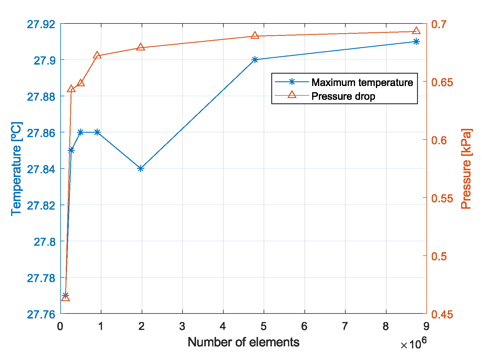
To define proper mesh for accurate results, a mesh independence study was developed using as a reference the particular case of the U-shape flow pattern design analysed on the geometrical comparison section (Section 3). To analyse the stabilization of the maximum temperature of the battery cell and the pressure drop of the cooling strategy, a sensitivity study was developed using seven models with different grid cell numbers. All cases were analysed defining constant inlet fluid flow and temperature at 0.4 L/min and 25 °C, consecutively. The flow rate was calculated using as a reference the characteristics of an indirect liquid cooling strategy–based cold plate [22]. The laminar model was defined to characterise the flow development because the Reynolds number was lower than 2300 in all case studies. To characterise the cell heat generation, a 1C pulse profile was implemented. Owing the prototype prismatisation casing, the interaction of the cell body with the climatic chamber environment was omitted. Therefore, an adiabatic definition was imposed on the battery cell surface that had no contact with the fluid. On the tab zone and on clamps an equivalent heat transfer coefficient of 25 W/m2K was set. As Figure 5 presents, both maximum temperature and pressure drop curves are stabilised with a mesh of 4,778,025 elements. The results variation maintains below 1% when the elements where increased to 8743816. Thus, it was concluded that the results are independent for the model of 4,778,025 elements [23,24].

3. Flow Pattern Design Selection

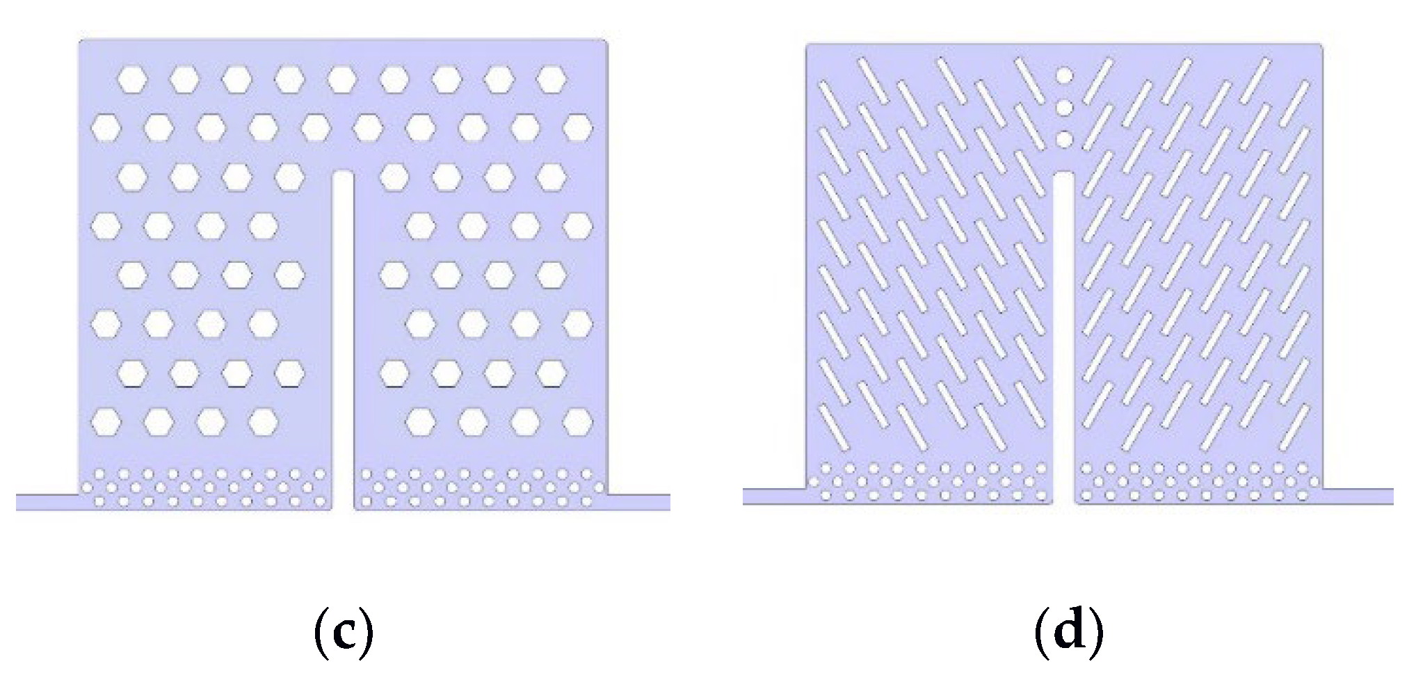
Before optimising the geometrical aspect of the prototype flow pattern, a design selection process was specified. This process was aimed at selecting among different flow pattern geometries analysed in the bibliography [23]. Defining the same working conditions, a comparison between the four main designs presented in Figure 6 was developed: U-shape, convex, honeycomb and airfoil. The objective of this study was to examine the impact of the geometry on the flow rate distribution and the resultant thermal performance and power consumption of each of the prototype.
To make the designs comparable, the same surface contact areas between the battery cell and flow patterns were defined: 0.026 m2. This was a conditioning parameter to define the same heat absorption capacity with the same fluid volume in all flow pattern designs.

3.1. Boundary Conditions

As a variable of the study, simulations at a flow rate of 0.1, 0.2, 0.4, 0.8, and 1.6 L/min were developed for each flow pattern design. This study of the flow rate range makes it possible to draw the curves for each case and, thus, to develop the comparison between the flow pattern designs in a wide working range. The inlet temperature of the fluid and the boundary temperature that mirrors the climatic chamber influence were defined at 25 °C. The battery cell working condition was defined with a 1C pulse test. These tests were developed until the thermal stabilization of the battery cell was achieved; thus, dynamics effects during the tests were avoided to analyse more clearly the influence of the parameters under study.

3.2. Results and Discussion

To analyse how the flow pattern geometry influences the performance of the battery cell and the auxiliary system, battery cell maximum temperature (Tmax), temperature homogeneity (ΔT), and the pumping power consumption related to the auxiliary system (Ph) were defined as the output variables. Figure 7 presents the steady state results of each case at flow rates of 0.1, 0.2, 0.4, 0.8, and 1.6 L/min.
As it is depicted in Figure 7a,b, at high flow rates, the airfoil design shows the lowest battery cell temperature and heterogeneity. However, at low flow rates the U-shape model presents the best thermal performance. Although the flow rate is greatly reduced, due to the channels of the U-shape design, the fluid is forced to flow all over the surface of the cell, avoiding the appearance of hot spots, and provides better homogeneity. For their part, considering the power consumption impact presented in Figure 7c, the convex and honeycomb models present the lowest pressure drop impact because the pattern design enables a greater freedom to the flow than the other design. Nevertheless, this freedom hinders the flow control and facilitates the development of hot spots. Consequently, both models show the highest maximum temperature and heterogeneity values.
Figure 7. Geometry comparison results of (a) battery cell maximum temperature (Tmax), (b) temperature homogeneity (ΔT), and (c) the pumping power consumption related to the auxiliary system (Ph) at different flow rate.
Wevj 13 00149 g007
To further analyse each design, Figure 8 shows the surface contact temperature between the fluid and the battery cell at a flow rate of 0.4 L/min. As it is presented, the U-shape model provides the most homogenous temperature distribution in the battery cell surface.
The objective of the prototype is to work with low flow rates to decrease the impact of the cooling strategy on the power consumption of the auxiliary system. Therefore, it is concluded that the U-shape design is the most appropriate one to develop the geometrical optimisation process.

4. Design Optimisation

4.1. Parametrisation of the Geometry

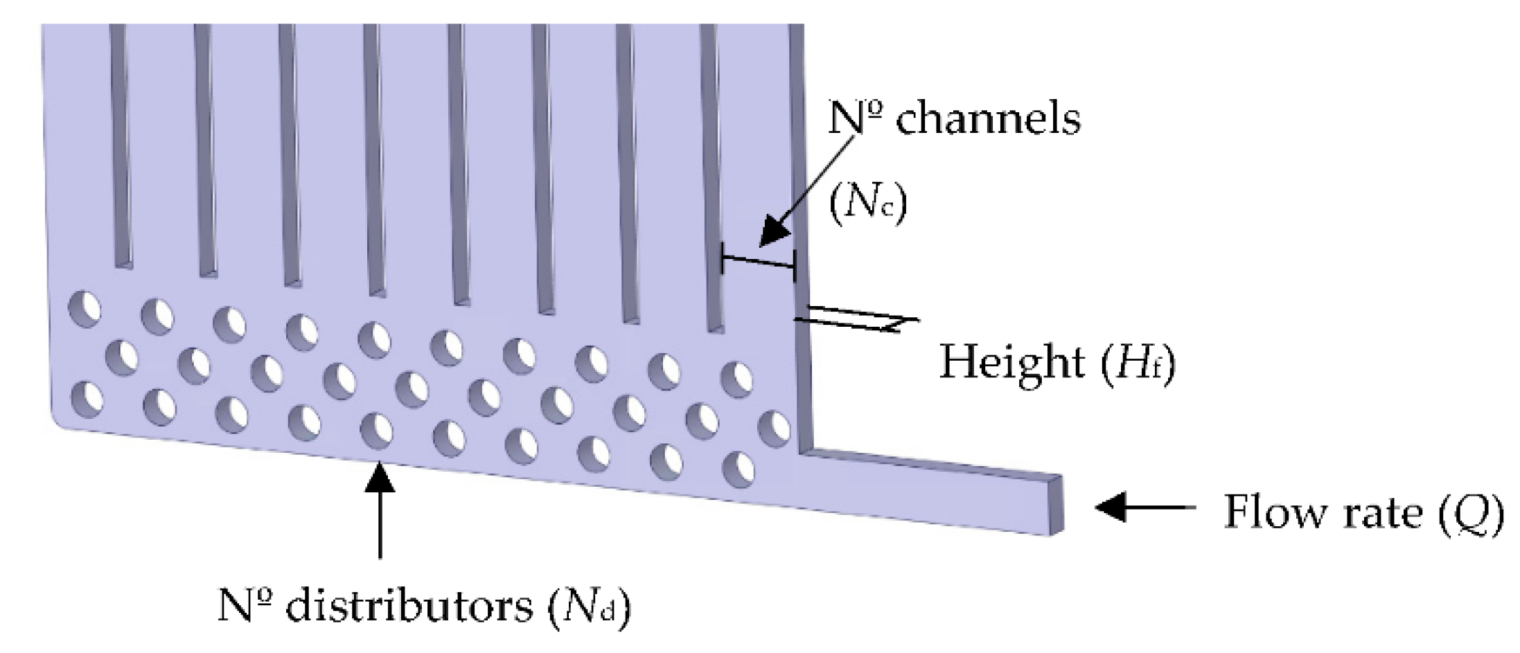
To develop the multi-objective optimisation of the selected U-shape flow pattern, four parameters were selected including the height of the fluid (Hf), the number of cooling channels (Nc), the number of inlet and outlet distributors (Nd), and the flow rate (Q). Figure 9 presents each parameter definition.
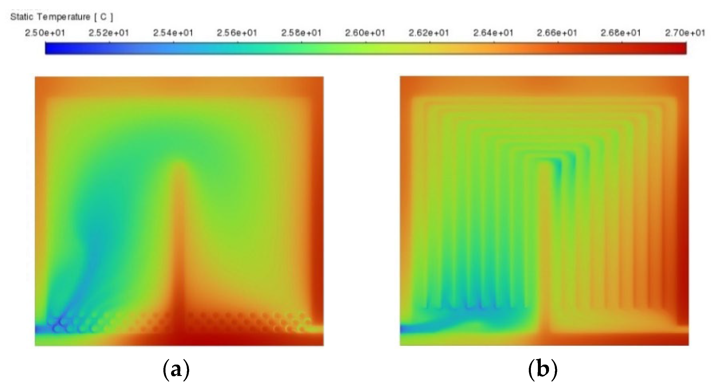
The height of the fluid was defined between 1 mm and 3 mm to study the impact of the fluid volume reduction on the energy density and the power consumption of the system. The number of cooling channels and distributors were defined between 3 and 9 channels and 10 and 30 distributors, respectively, to analyse the influence of those components and to spread the fluid in a homogeneous way through all the cooling space. This definition was based on the cell surface temperature analysis presented in Figure 10. For each case the cooling channels and the distributors were omitted and the temperature of the cell surface analysed. Considering Figure 10, results show that the lack of these components creates a heterogeneous fluid distribution developing hot spot areas on the battery cell surface. Finally, inlet flow rate was defined as variable of study to analyse how impacts this input the relationship between the thermal performance of the battery system and the power consumption of the auxiliary system.

4.2. Output Variables

To evaluate the performance of each case, four objective output variables were defined, including maximum temperature (Tmax), temperature homogeneity (ΔT), system volumetric energy density (VED), and system power consumption (Ph). As it is presented in Figure 11, the first two variables (Tmax and ΔT) were related to the cell level design to analyse how the strategy controls the thermal behaviour of the battery system. Then, scaling up to a battery module of 24 battery cells, the impact of each cooling strategy on the system volumetric energy density (VED) and system power consumption (Ph) were analysed.

4.3. Optimisation Process Definition

To evaluate how the flow rate definition and the geometrical parameters influence the performance of the strategy, a two-level full factorial matrix was defined. This is a numerical analysis method which considers all the possible variations between the defined factors. Hence, considering four variables of study, a simulation process with 16 simulation cases was defined. With the proposed analysis, all the interactions between Hf, Nc, Nd, and Q were determined. To investigate the importance of the defined variables on the output results of the full factorial design, analysis of variance (ANOVA) was employed. This is, a statical model that evaluates the importance of the defined factors by comparing the response variable means at the defined factor levels. To properly develop the regression equations, all variations up to the second order of interaction between the defined factors were first analysed. Then, the most relevant interactions were selected by defining a significance level of 0.05. Once the most influential factors conditioning the output variable were selected, the factorial design was analysed again, and the ANOVA results were extracted. With this information, the regression coefficients were calculated, and regression equations were developed for each output variable. To analyse the reliability of these regression model, values of R2 (Adequate), R2 (Predicted), and R2 (Adjusted) were examined, and the residual normal plots were presented. After the validation, the optimum case was selected considering the composite desirability function, where the optimum case selection process guideline was defined assigning specific weight and importance values for each of the proposed output variables.

4.4. Results and Analysis

The corresponding results of the two-level full factorial design are presented in Table 2. Among the results, cell level Tmax and ΔT, and module level VED and Ph output variable results can be observed for all the possible variations between Hf, Nc, Nd, and Q.
To obtain the coefficients of the regression model, ANOVA was used. As it was mentioned in the optimisation procedure section, these coefficients were evaluated using the most relevant interactions effects between the defined factors. Therefore, the coefficients defined for the regression equations were the ones that presents a significance level below 0.05. Considering this guideline, the following regression equations were obtained for the output variables of cell maximum temperature (Tmax), cell surface temperature homogeneity (ΔT), system volumetric energy density (VED), and system power consumption (Ph):
Tmax = 27.6 + 0.28 Hf − 0.38 Q
ΔT = 0.58 + 0.06 Hf − 0.014 Nc + 0.022 Nd − 0.146 Q + 0.008 Hf Nd + 0.01 Hf Q
VED = 264.24 − 15.54 Hf
Ph = 0.364 − 0.316 Hf + 0.039 Nd + 0.302 Q − 0.031 Hf Nd − 0.261Hf Q + 0.035 Nd Q
To analyse the reliability of the regression model, values of R2 (Adequate), R2 (Predicted), and R2 (Adjusted) were analysed. These are significance indexes that present the adequate quality, the quality of the predicted regression models, and the quality of the models after adjustment, respectively. Considering results from Table 3, index values agree for Tmax, ΔT, VED, and Ph. Index values for VED were 100% in all R2 cases. This result means that there is not variability on results, as the volumetric energy density VED is the only one proportional to a single parameter (Hf). Therefore, the quality and the correlation of these values demonstrates the reliability of the regression models.
Apart from R2 index values, it is important to make sure that the results of the residuals for each response are consistent. Figure 12 presents the normal residual plots for each output variable. As it is shown the residuals are normally distributed, which means that there is a good agreement between the predicted and actual values. Figure 12c corroborates the interpretation made with R2 index values for the volumetric energy density VED. Therefore, it was confirmed that VED was uniquely and exclusively proportional to Hf. These results demonstrated that the proposed regression models could predict adequately the variability of the output parameters. The reliability of the regression models is therefore justified.
After validating the regression models, the principal influences of the optimisation parameters on the defined output variables were analysed. As it is presented in the regression equation of cell maximum temperature (Equation (1)), the height of the fluid channel (Hf) and the inlet flow rate definitions (Q) were the main parameters that influences the maximum temperature of the cell body. This means that the influence of the number of channels (Nc) and distributors (Nd) for Tmax is negligible. However, the impact of those input parameters is appreciated on the variability of the temperature homogeneity of the battery cell surface (Equation (2)). With a higher Nc number, the temperature difference of the cell surface increases. In contrast, the effect of Nd is the opposite. Therefore, the results recommended to decrease the number of distributors and increase the number of channels to improve the temperature homogeneity of the battery cell surface.
As mentioned above, the volumetric density (Equation (3)) is influenced only by the parameter Hf. Therefore, analysing the results, the objective of developing systems with high volumetric energy density will be achieved by reducing this parameter Hf as much as possible. In this case, the minimum value of 1 mm for Hf is the one that gives the best results of volumetric energy density.
Finally, to achieve the objective of decreasing the power consumption of the system, the regression equation (Equation (4)) presents that all the parameters influence it. However, analysing the estimated coefficients for Ph, it is observed that Hf, Q, and the interaction between them (Hf Q) have more impact than the Nd and related interactions. The power consumption of the system is based on the pressure drop defined by the fluid; therefore, Hf and Q influence is coherent. The pressure drop is related in a quadratic way by the velocity of the fluid [25]. Thus, to decrease the power consumption of the system lower fluid velocity profiles were recommended. Studying the influence of the parameters Nc and Nd it can be observed that the rise in the number of channels and distributors increases the power consumption of the system. Therefore, it is concluded that the quantity of these components should be minimised for achieving the desired fluid distribution to maintain the lowest impact on the power consumption of the system.
Once the reliability of the regression models was validated, and the principal influences of the optimisation parameters on the defined output variables were analysed, the composite desirability function for Tmax, ΔT, VED, and Ph was implemented. This function calculates, according to the desirability values defined for each output variable, the optimal case within the range of the proposed two-level full factorial model results.
To examine results that ensure the best performance of the battery cell, first, a composite desirability function was developed with the maximum desirability values defined for Tmax and ΔT. In this case, the optimum values to ensure the best thermal performance were Hf = 1 mm, Nc = 9, Nd = 10, and Q = 0.4 L/min. This configuration maintains the highest volumetric energy density at the expense of a considerable increase in the Ph output parameter. Therefore, VED and Ph were implemented with a lower weight impact and the same importance on the composite desirability function to develop a multi-objective optimisation that minimises the power consumption of the strategy and maximises the volumetric energy density of the system. For this case, the corresponding values of the design variables were Hf = 1 mm, Nc = 9, Nd = 10, and Q = 0.13 L/min. Maintaining the maximum volumetric energy density of 279.7 Wh/L, this configuration implies an increase in the maximum temperature from 27.02 °C to 27.72 °C, and the temperature difference was increased by 0.3 °C. However, the power consumption of the system was decreased by 90% from 1.16 W to 0.11 W.

5. Conclusions

In this work, a parametric optimisation of a direct liquid cooling strategy is proposed for a large-scale lithium-ion pouch-type cell as a reference. First, the simulation model was developed and validated with experimental results. Moreover, a non-uniform heat generation was defined in the battery model to adequately represent the temperature distribution of the large-scale pouch-type cell. Then, a comparison between different flow pattern designs was developed to analyse the influence of the fluid distribution geometry. Finally, a parametric optimisation process was implemented to obtain the optimal relationship between the thermal performance of the battery cell, the volumetric energy density of the system, and the power consumption of the strategy. The analysis carried out in the present work gave rise to the following conclusions:
  • At flow rates below 0.4 L/min, the flow distribution channels defined on the U-shape design improve the fluid dynamical aspect of the cooling strategy, maintaining the highest thermal performance of the battery cell without increasing the power consumption. It was therefore selected to develop the parametric optimisation process.
  • Developed surrogate models presented that the most critical parameters that influence the output variable results were the height of the fluid channel (Hf) and the flowrate definition (Q), which are directly related to the fluid local velocity.
  • The number of channels (Nc) increases the power consumption of the system (Ph) while decreasing the thermal heterogeneity of the battery cell (ΔT). Therefore, it is recommended to decrease the number of channels remaining the thermal distribution of the cell within the optimal range.
  • The number of distributors (Nd) increases the power consumption of the system (Ph) and the thermal heterogeneity of the battery cell (ΔT). However, a minimum number of components to adequately distribute the inflow and outflow are necessary, thus avoiding hot spots in the system.
  • The proposed parametric optimisation defined the optimum design of the DLC strategy that ensures the optimal relationship among Tmax, ΔT, VED, and Ph. The corresponding values of the design parameters were Hf = 1 mm, Nc = 9, Nd = 10, and Q = 0.13 L/min. This design case maintains Tmax at 27.72 and ΔT at 0.65 with the maximum VED value and reducing Ph by 90%.

Author Contributions

Conceptualization, M.L.-E. and G.V.N.; methodology, M.L.-E. and G.V.N.; software, I.G.G. and P.F.A.; validation, M.L.-E., I.G.G. and P.F.A.; formal analysis, M.L.-E.; investigation, M.L.-E.; resources, M.L.-E.; data curation, M.L.-E., G.V.N. and J.B.A.; writing—original draft preparation, M.L.-E.; writing—review and editing, M.M.-A., J.B.A. and P.F.A.; visualization, M.L.-E.; supervision, G.V.N., M.M.-A., J.B.A. and P.F.A.; project administration, M.M.-A. All authors have read and agreed to the published version of the manuscript.

Funding

This research did not receive any specific grant from funding agencies in the public, commercial, or not-for-profit sectors.

Institutional Review Board Statement

Not applicable.

Informed Consent Statement

Not applicable.

Data Availability Statement

Not applicable.

Conflicts of Interest

The authors declare no conflict of interest.

Abbreviations

The following abbreviations are used in this manuscript:
ANOVAanalysis of variance
CFDcomputational fluid dynamics
DLCdirect liquid cooling
DoEdesign of experiments
ECMequivalent circuit model
EVelectric vehicle
HEVhybrid electric vehicle
HPheat pipes
HPPChybrid pulse power characterization
ILCindirect liquid cooling
LCliquid cooling
NMCnickel manganese cobalt
OCVopen circuit voltage
PCMphase change material
SOCstate of charge
TECthermoelectric material
UDFuser-defined functions
VEDvolumetric energy density

References

  1. International Energy Agency. Global EV Outlook 2020. Glob. EV Outlook 2020, 191, 116565. [Google Scholar]
  2. Choudhari, V.; Dhoble, A.; Sathe, T. A review on effect of heat generation and various thermal management systems for lithium ion battery used for electric vehicle. J. Energy Storage 2020, 32, 101729. [Google Scholar] [CrossRef]
  3. Han, X.; Lu, L.; Zheng, Y.; Feng, X.; Li, Z.; Li, J.; Ouyang, M. A review on the key issues of the lithium ion battery degradation among the whole life cycle. eTransportation 2019, 1, 100005. [Google Scholar] [CrossRef]
  4. Patil, M.S.; Seo, J.-H.; Panchal, S.; Jee, S.-W.; Lee, M.-Y. Investigation on thermal performance of water-cooled Li-ion pouch cell and pack at high discharge rate with U-turn type microchannel cold plate. Int. J. Heat Mass Transf. 2020, 155, 119728. [Google Scholar] [CrossRef]
  5. Kim, J.; Oh, J.; Lee, H. Review on battery thermal management system for electric vehicles. J. Appl. Therm. Eng. 2019, 149, 192–212. [Google Scholar] [CrossRef]
  6. Rouaud, C. Automotive Thermal Management, Online Conference. 19.11.2020. Available online: https://lp.bcf-events.com/automotive-thermal-management-online-conference-2020/ (accessed on 19 November 2020).
  7. Chung, Y.; Kim, M.S. Thermal analysis and pack level design of battery thermal management system with liquid cooling for electric vehicles. Energy Convers. Manag. 2019, 196, 105–116. [Google Scholar] [CrossRef]
  8. Yang, C.; Cao, L. The Role of Interfacial Thermal Resistance in Li-Ion Battery Thermal Management. In Proceedings of the ASME 2019 International Technical Conference and Exhibition on Packaging and Integration of Electronic and Photonic Microsystems, Anaheim, CA, USA, 7–9 October 2019. [Google Scholar] [CrossRef]
  9. 3M. 3M Novec 7000 Engineered Fluid Product Information. 2005, pp. 1–6. Available online: http://multimedia.3m.com/mws/mediawebserver?66666UuZjcFSLXTtlXftMxMVEVuQEcuZgVs6EVs6E666666-- (accessed on 16 April 2020).
  10. XING Mobility Dynamic Power on Demand. 2022. Available online: https://www.xingmobility.com/assets/pdf/XingMobility_DynamicPower_OnDemand.pdf (accessed on 3 April 2020).
  11. Battery, K. Kreisel Battery Pack. 2022. Available online: https://www.kreiselelectric.com/ (accessed on 10 March 2020).
  12. Park, S.; Jung, D. Battery cell arrangement and heat transfer fluid effects on the parasitic power consumption and the cell temperature distribution in a hybrid electric vehicle. J. Power Sources 2013, 227, 191–198. [Google Scholar] [CrossRef]
  13. Sundin, D.W.; Sponholtz, S. Thermal Management of Li-Ion Batteries with Single-Phase Liquid Immersion Cooling. IEEE Open J. Veh. Technol. 2020, 1, 82–92. [Google Scholar] [CrossRef]
  14. Dubey, P.; Pulugundla, G.; Srouji, A. Direct Comparison of Immersion and Cold-Plate Based Cooling for Automotive Li-Ion Battery Modules. Energies 2021, 14, 1259. [Google Scholar] [CrossRef]
  15. Tan, X.; Lyu, P.; Fan, Y.; Rao, J.; Ouyang, K. Numerical investigation of the direct liquid cooling of a fast-charging lithium-ion battery pack in hydrofluoroether. Appl. Therm. Eng. 2021, 196, 117279. [Google Scholar] [CrossRef]
  16. Patil, M.S.; Seo, J.-H.; Lee, M.-Y. A novel dielectric fluid immersion cooling technology for Li-ion battery thermal management. Energy Convers. Manag. 2020, 229, 113715. [Google Scholar] [CrossRef]
  17. Le, Q.; Shi, Q.; Liu, Q.; Yao, X.; Ju, X.; Xu, C. Numerical investigation on manifold immersion cooling scheme for lithium ion battery thermal management application. Int. J. Heat Mass Transf. 2022, 190, 122750. [Google Scholar] [CrossRef]
  18. Battery University. Battery University—BU-301a: Types of Battery Cells. 2021. Available online: https://batteryuniversity.com/article/bu-301a-types-of-battery-cells (accessed on 25 February 2020).
  19. Tran, M.-K.; Mevawala, A.; Panchal, S.; Raahemifar, K.; Fowler, M.; Fraser, R. Effect of integrating the hysteresis component to the equivalent circuit model of Lithium-ion battery for dynamic and non-dynamic applications. J. Energy Storage 2020, 32, 101785. [Google Scholar] [CrossRef]
  20. Li, Y.; Chen, M.; Bai, F.; Song, W.; Feng, Z. Thermal equilibrium characteristic of large-size lithium-ion pouch battery: Resting time between charge and discharge. Energy Procedia 2019, 158, 2623–2630. [Google Scholar] [CrossRef]
  21. Wu, X.; Lv, S.; Chen, J. Determination of the Optimum Heat Transfer Coefficient and Temperature Rise Analysis for a Lithium-Ion Battery under the Conditions of Harbin City Bus Driving Cycles. Energies 2017, 10, 1723. [Google Scholar] [CrossRef] [Green Version]
  22. Larrañaga, M. Design and implementation of a Direct Liquid Cooling strategy for HEV/EV focus on a pouch type cell body refrigeration. In Proceedings of the Thermal Management Systems Symposium (21TMSS), Online, 12–14 October 2021. [Google Scholar]
  23. Li, M.; Wang, J.; Guo, Q.; Li, Y.; Xue, Q.; Qin, G. Numerical Analysis of Cooling Plates with Different Structures for Electric Vehicle Battery Thermal Management Systems. J. Energy Eng. 2020, 146, 04020037. [Google Scholar] [CrossRef]
  24. Panchal, S.; Khasow, R.; Dincer, I.; Agelin-Chaab, M.; Fraser, R.; Fowler, M. Numerical modeling and experimental investigation of a prismatic battery subjected to water cooling. Numer. Heat Transfer Part A Appl. 2017, 71, 626–637. [Google Scholar] [CrossRef]
  25. Brown, G.O. The History of the Darcy-Weisbach Equation for Pipe Flow Resistance. Proc. Environ. Water Resour. Hist. 2002, 40650, 34–43. [Google Scholar] [CrossRef] [Green Version]
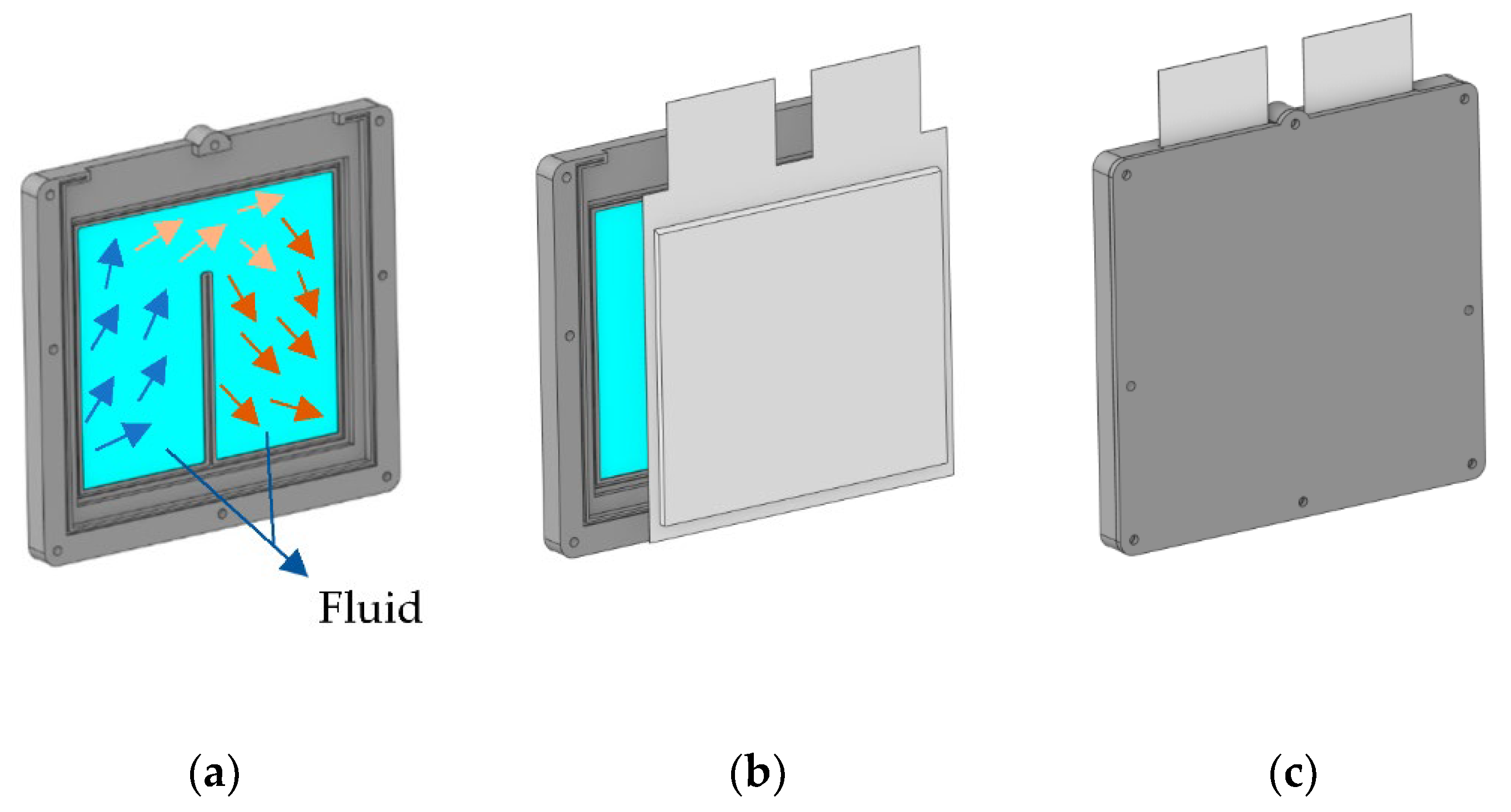
Figure 1. Reference model (a) flow distribution, (b) principal components, and (c) assembly.
Wevj 13 00149 g001
Figure 2. Principal components defined in the simulation model.
Wevj 13 00149 g002
Figure 3. Battery cell model validation with experimental (a) voltage and (b) surface temperature distribution in a range of 100–20% SOC of a 1C discharge test.
Wevj 13 00149 g003
Figure 4. Battery cell model heat generation validation with experimental heat generation information (80–20% SOC range).
Wevj 13 00149 g004
Figure 5. Mesh independence analysis with the maximum temperature of the battery cell (°C) and pressure drop (kPa).
Wevj 13 00149 g005
Figure 6. Flow pattern designs (a) U-shape, (b) convex, (c) honeycomb, and (d) airfoil.
Wevj 13 00149 g006aWevj 13 00149 g006b
Figure 8. Battery cell surface temperature distribution at 0.4 L/min of flow rate for (a) U-shape, (b) convex, (c) honeycomb, and (d) airfoil designs.
Wevj 13 00149 g008
Figure 9. Parameters implemented in the optimisation process.
Wevj 13 00149 g009
Figure 10. Battery cell surface temperature distribution for (a) a cooling design without channels and (b) a cooling design without distributors.
Wevj 13 00149 g010
Figure 11. Output variable analysis level explanation.
Wevj 13 00149 g011
Figure 12. Residual normal plots for the output variables of (a) Tmax, (b) ΔT, (c) VED, and (d) Ph.
Wevj 13 00149 g012
Table 1. Properties of the battery cell, the clamps, and the dielectric fluid, for 25 °C.
PropertyBattery CellClampsDielectric Fluid
MaterialBattery cellAluminiumMineral oil
Kinematic Viscosity (mm2/s)--4.3
Heat Capacity (J/kgK)13068712130
Thermal conductivity (W/mK)x,y: 17.9/z: 0.65202.40.135
Density (kg/m3)21832719774
Resistivity (MΩm)-->5 × 10⁶
Table 2. The corresponding simulation cases of the two-level full factorial design and the output variable results of each case.
N° SimulationsHf (mm)NcNdQ (L/min)Cell LevelModule Level
Tmax (°C)ΔT (°C)VED (Wh/L)Ph (W)
139300.4027.520.51248.700.109
219300.4027.000.37279.781.455
333300.4027.510.56248.700.095
413300.4026.980.38279.781.301
539100.4027.560.47248.700.076
619100.4027.020.35279.781.162
733100.4027.510.49248.700.069
813100.4026.980.36279.781.060
939300.1328.360.78248.700.009
1019300.1327.730.68279.780.131
1133300.1328.310.84248.700.007
1213300.1327.70.71279.780.118
1339100.1328.370.73248.700.006
1419100.1327.720.65279.780.115
1533100.1328.270.76248.700.005
1613100.1327.690.67279.780.103
Table 3. Values of R2 (Adequate), R2 (Predicted), and R2 (Adjusted) for the output variables Tmax, ΔT, VED, and Ph.
R2 (Adequate)R2 (Predicted)R2 (Adjusted)
Tmax90.32%85.34%88.84%
ΔT99.68%99.00%99.47%
VED100%100%100%
Ph99.59%98.37%99.23%
Publisher’s Note: MDPI stays neutral with regard to jurisdictional claims in published maps and institutional affiliations.