Abstract
The dual-motor EV (Electric Vehicle) is increasingly favored by manufacturers for its excellent performance in terms of power and economy. How to further reduce its energy consumption and make full use of the dual-motor energy recovery is an important support to improve the overall vehicle economy and realize the “dual carbon” strategy. For the dual-motor EV architecture, the motor model, power battery loss model and vehicle longitudinal braking force model are established and the energy recovery-dominated regenerative braking torque distribution (RBD) rule of the dual motors is designed. Based on genetic algorithm (GA) theory and taking into account SOC, vehicle speed and braking intensity, a regenerative-braking torque optimization method is proposed that integrates energy recovery and braking stability. The braking intensity of 0.3 and the initial vehicle speed of 90 km/h are selected for verification. Compared with the rule method, the energy recovery and stability are improved by 22.8% and 4.8%, respectively, under the genetic algorithm-based and energy recovery-dominated regenerative-braking torque distribution (GA-RBD) strategy. A variety of conditions are selected for further strategy validation and the result shows that compared with the rule-based method, both energy recovery and braking stability are improved as braking speed and braking intensity increase under the GA-RBD strategy.
1. Introduction
The Energy Saving and New Energy Vehicle Technology Roadmap (Version 2.0) indicates the development direction of the automotive industry during the next 15 years. By 2035, the annual sales of energy-efficient vehicles and new energy vehicles will each account for 50% and the transformation of the automotive industry towards electrification. Dual-motor EVs are favored by an increasing number of manufacturers for their outstanding performance in terms of power and economy. According to statistics, the vehicle braking energy loss accounts for more than 43% in typical urban conditions, and making full use of the dual-motor EV regenerative braking for energy recovery is an important supportive role in improving the economy of the whole vehicle and realizing the “double carbon” strategy [1]. As a result, regenerative braking systems [2,3,4,5] are being studied in greater depth by national and international scholars.
To maximize energy recovery, Pennycott et al. [6] designed a constant proportional regenerative braking strategy based on the control distribution, which considered the influence of motor operating characteristics on regenerative braking. Considering the different braking conditions, Pei [7] proposes a coordinated control strategy for the electro-hydraulic braking of distributed electric vehicles, aiming to improve the comprehensive performance of the system in terms of energy regeneration and braking stability. Maia et al. [8] proposed a fuzzy controller-based distribution strategy for regenerative braking torque, taking into account vehicle acceleration, bumpiness and road inclination and verifying the effectiveness of this distribution strategy under the real road experiments. Xu [9] proposed a new braking torque distribution strategy based on model predictive control which aimed to achieve both braking stability and optimal energy recovery under the constraints of regenerative braking. Chen [10] proposed a hierarchical cooperative control for the electromechanical brake-by-wire system (EBW) to solve the coordination of mechanical and regenerative braking and ensure vehicle stability and maximum energy regeneration.
Existing studies on regenerative braking energy recovery have generally focused on the effects of braking intensity, vehicle speed and residual power on energy recovery and braking safety during regenerative braking. The relevant research on composite braking has mainly focused on models with the single-motor configuration where the energy recovery power flow path is relatively simple, and less research has been conducted on braking energy recovery in the dual-motor configuration. The research object of this paper has characteristics that dual motors can participate in energy recovery. Compared to the single-motor configuration, the dual-motor driven vehicles have the multiple power flow paths for energy recovery, and by distributing the motor braking torque, the motors can work to a greater extent in the high efficiency zone. Thus, fully considering the structural characteristics of dual-motor EVs and establishing a regenerative braking strategy for dual-motor EVs that integrates energy recovery and braking stability to further improving the regenerative braking energy recovery rate has important theoretical significance and engineering value. The contributions of the proposed regenerative braking method lie in the following three aspects:
(i) A energy recovery-dominated regenerative-braking torque distribution rule of the dual motors is designed, which takes into account the characteristics that both motors can participate in the energy recovery characteristics.
(ii) Considering the variation of SOC, vehicle speed and braking intensity, a dual-motor EV regenerative-braking optimization method that integrates energy recovery and braking stability is proposed.
(iii) The energy recovery rate and braking stability are integrated into one control objective by weighting coefficients, and the optimal value of torque distribution is solved by genetic algorithm under the corresponding weighting coefficients.
Therefore, this paper proposes a dual-motor EV regenerative braking strategy that integrates energy recovery and braking stability. Both the energy recovery rate and braking stability are improved compared to the rule-based method. The rest of the paper is organized as follows. In Section 2, the powertrain configuration and main component models of the dual-motor EV are presented. In Section 3, the energy-recovery rate-dominated regenerative-braking torque-distribution rule is designed and a regenerative-braking torque-optimization strategy that incorporates braking energy recovery and braking stability is proposed. In Section 4, the results of the two distribution strategies are compared and the effectiveness of the strategies is demonstrated. At last, conclusions are given in Section 5.
2. Model of a Dual-Motor EV Regenerative Braking System
2.1. Dual-Motor EV System Configuration
The configuration of one dual-motor EV in this paper is shown in Figure 1, which mainly include a coupled structure of two motors and two gear pairs, hydraulic lines, control units, battery packs and other components. Motor 1 and motor 2 can individually or jointly provide the braking torque in regenerative mode.
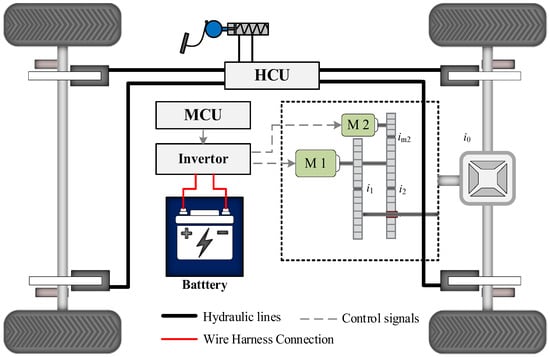
Figure 1.
Schematic diagram of an EV system structure.
When the driver applies the brake pedal to apply the brakes, the Vehicle Control Unit (VCU) determines the braking torque to be assumed by the Motor Brake System (MBS) and the Hydraulic Brake System (HBS) based on information such as current vehicle speed, braking intensity and battery SOC. The motor braking torque and hydraulic braking torque are controlled by the Motor Control Unit (MCU) and the Hydraulic Control Unit (HCU), respectively.
2.2. Motor Model
Permanent magnet synchronous motors are used in this configuration of EV. It offers the advantages of small size, high-speed, high-power density and flexibility in shape and size. Compared to other types of motors, permanent magnet synchronous motors are more efficient and have a longer range. Moreover, China is rich in rare earth resources and the cost of using permanent magnet-synchronous stand-alone machines is lower.
Since the focus of this paper is on the regenerative-braking torque-distribution strategy, the transient characteristics of the motors are simulated by first-order delays. The equations are shown as follows:
where τm1 and τm2 denote the time constants of the first-order system; Tm1, Tm2 denote the actual output torque
The generation efficiency maps of motor 1 and motor 2 are measured experimentally, as shown in Figure 2 and Figure 3.
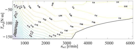
Figure 2.
Efficiency map of motor 1.
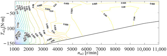
Figure 3.
Efficiency map of motor 2.
2.3. Power Battery Loss Model
The charging efficiency of the power battery directly influences the regenerative-braking energy recovery, and its power loss can be expressed as follows:
where Vo denotes the battery terminal voltage; Rc and Rc_dis denote the battery equivalent resistance and the battery discharge resistance, respectively; and Pm denotes the total generated power of the motor.
2.4. Vehicle Braking Model
The force analysis of the braking process is shown in Figure 4.
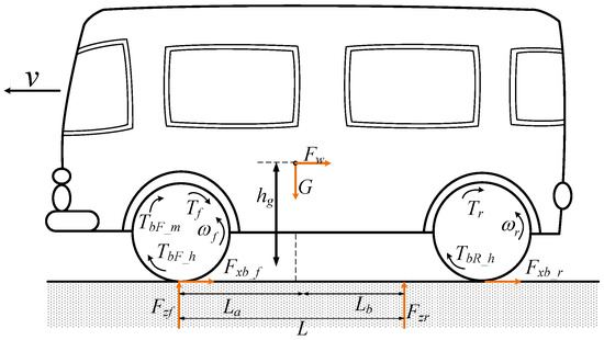
Figure 4.
Vehicle force analysis diagram of the braking process.
The vehicle longitudinal dynamics equations are as follows:
where v denotes the longitudinal speed of the vehicle; m denotes the overall vehicle mass; Fxb_f and Fxb_r denote the ground braking force of the front wheel and the rear wheel, respectively; Fw and Ff denote the wind resistance and the rolling resistance of the vehicle; Cd and fv indicate the wind resistance coefficient and the rolling resistance coefficient; and Av is expressed as the equivalent wind resistance area.
The torsional dynamics equations of the front wheel and the rear wheel are expressed as follows:
where Jf and Jr denote the equivalent rotational inertia of the front and rear wheels, respectively; Rv indicates the wheel radius; ωf and ωr represent the front and rear wheel rotational speeds; TbF_h and TbR_h represent the hydraulic braking force of the front and rear wheels. TbF_m is the regenerative braking torque applied to the wheel end by the dual motor, expressed as follows:
where Tm1 and Tm2 denote the output torque of motor 1 and motor 2; im2 and i0 denote the output reduction ratio of motor 2 and the final drive ratio, respectively; and ig1 and ig2 represent the corresponding reduction ratios of motor 1 and motor 2 in the current operating mode of the coupling mechanism.
The detailed parameters of the EV and related components studied in this paper are shown in Table 1.

Table 1.
Key parameters of vehicle powertrain.
3. Regenerative Braking Strategy for Dual-Motor EV
3.1. Energy Recovery-Dominated Regenerative Braking Torque Distribution (RBD) Rule
Combined with the dual-motor EV configuration in this paper, an energy recovery rate-dominated regenerative braking torque distribution rule is proposed, and its specific distribution strategy is shown in Figure 5. Where FbF and FbR denote the front wheel braking torque and the rear wheel braking torque, respectively.
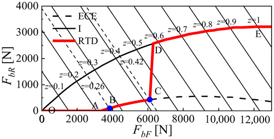
Figure 5.
Regenerative braking torque distribution rules dominated by energy recovery.
From the Figure 5, the braking force operating points under the RBD rule are between the I curve and the ECE regulation curve. With the braking intensity increases, the front and rear wheel braking forces are distributed along the OABCDE curve. The term z denotes braking severity.
(1) OA segment: When z < 0.21, the braking intensity is so light that braking stability does not need to be considered. In this case, the braking force is supplied exclusively by motor 2 to the front wheels and the braking force of the rear wheels is 0.
(2) AB segment: When 0.21 ≤ z < 0.26, with the braking intensity increasing, the rear wheels start to engage the brakes and the braking torque is supplied exclusively by the hydraulic system. In addition, the braking force of the front wheels is still provided only by motor 2, and the braking torque of motor 2 reaches a maximum at point B.
(3) BC segment: When 0.26 ≤ z < 0.42, the braking force provided by motor 2 is no longer sufficient for the braking of the front wheels, so that motor 1 and motor 2 together provide braking force to the front wheels. At the point C, the braking torque of motor 1 and motor 2 reaches its maximum value at the same time.
(4) CD segment: When 0.42 ≤ z < 0.58, motor 1 and motor 2 are all involved in the braking process and have reached their peak state. At this point, the energy recovery rate of the system has been ensured, and in order to take into account the braking stability at the same time, the braking force is distributed according to the f-curve with φ = 0.58. At this stage, the hydraulics start to participate in the front wheel braking, and as the braking intensity increases, the curve gradually approaches the I curve.
(5) DE segment: When 0.58 ≤ z ≤ 1, in this phase, the braking stability is predominant, the braking force distribution curve exactly follows the I-curve and the braking torque is provided by the hydraulic system and the motor.
3.2. Regenerative Braking Torque Optimisation Incorporating Energy Recovery and Braking Stability
GA-RBD distribution strategy architecture diagram is shown in Figure 6.
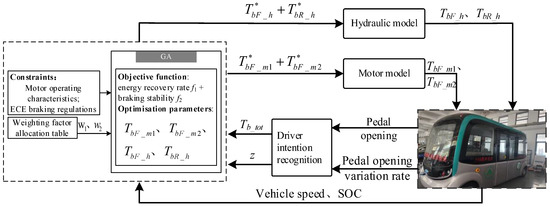
Figure 6.
GA-RBD distribution strategy architecture diagram.
Through the brake intention module, the driver’s required braking torque and braking intensity are calculated. Based on the current vehicle speed, battery SOC and other information, the weighting coefficients under the current state are obtained according to the weighting allocation table. The optimal values of the assigned braking torque under this weighting factor are calculated by the genetic algorithm, and the corresponding reference torque information of each actuator is sent to the motor system and the hydraulic braking system. Finally, the actuator outputs the braking torque to complete the braking process.
In order to take into account both the braking stability and the energy recovery rate of the vehicle, both the energy recovery rate and the braking stability were selected as optimization objectives in this study.
The energy recovery rate is defined as the ratio of the energy recovered by the battery to the kinetic energy lost during braking, expressed as follows:
where nw denotes wheel end rotational speed; η1 and η2 denote the generation efficiency of motor 1 and motor 2, respectively; vt and v0 represent the current vehicle speed and the initial braking speed; and Plos denotes the loss of power for battery charging.
Braking stability is defined as the degree of deviation between the front and rear axle braking torque distribution curves and the ideal braking torque distribution curve, which is expressed as follows:
where TIf and TIr represent the front and rear wheel braking torques corresponding to when the braking force distribution curve is on the ideal distribution curve, respectively.
The comprehensive optimization objectives of the final design are as follows:
where w1 and w2 denote the corresponding weighting factors.
The regenerative braking system will stop working when the vehicle speed is below 20 km/h or when the battery SOC value is high, the former to take into account that the motor does not recover enough braking energy at low speeds, and the latter to prevent the battery from being overcharged. Focusing on energy recovery at low speeds or at low braking intensities, the weighting factor w1 will be increased. Conversely, at high speeds or high braking intensities the focus is on braking stability and the weighting factor w1 will be reduced, w2 increased. When braking under normal operating conditions, the weighting coefficients are taken to be 0.5, respectively, in order to take into account the effects of both braking energy recovery and braking stability.
Taking into account SOC, vehicle speed and braking intensity, the weighting factors are set as shown in Figure 7.
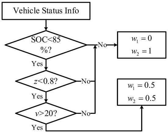
Figure 7.
Rules for setting weighting factors.
The optimization objective selected by the genetic algorithm is a comprehensive index of braking energy recovery and braking stability after considering weighting factors (as shown in Equation (11)). The motor 1 braking torque, motor 2 braking torque, front wheel hydraulic braking force and rear wheel hydraulic braking force are used as genes for the individuals in the genetic algorithm, and the objective function is solved using the genetic algorithm to obtain the torque distribution corresponding to the optimal value.
The Genetic Algorithm (GA) [11] process is shown in Figure 8 and mainly consists of three parts as follows:
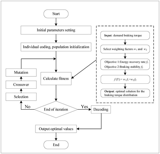
Figure 8.
GA algorithm optimization process.
- (1)
- Initialization
Individual coding and population and initialization. The coding method adopted in this paper is real number coding and the optimisation parameters of the genetic algorithm are set as follows: the population size is set to 30, the crossover probability and variation probability are set to 0.95 and 0.1, respectively, and the number of stopping iterations is 50.
Where the size of the population is related to the degree of dispersion for the optimised problem, and the larger the dispersion, the larger the population size to improve the speed of convergence [12]. In this paper the linear relationship between the torque and the objective function is obvious, so the population can be relatively small and is set to 30.
- (2)
- Calculation of the fitness
Calculate the value of the fitness function corresponding to each individual f(TI), and determine whether it satisfies the termination condition of the genetic algorithm; if it does, then output the optimal solution, otherwise continue to evolutionary operations.
- (3)
- Evolutionary operations
Evolutionary operations are the heart of genetic algorithms and include selection, crossover and mutation. In nature, the further adapted individuals are, the more likely they are to reproduce offspring. Based on fitness, the system selects a certain number of individuals to cross and mutate in order to produce offspring and form new populations, and repeats the operation in (2).
4. Results Verification
In order to verify the effectiveness of the GA-RBD allocation strategy algorithm, the optimization was first carried out at different braking intensities and speeds to obtain the vehicle speed-braking intensity-braking torque maps, as shown in Figure 9.
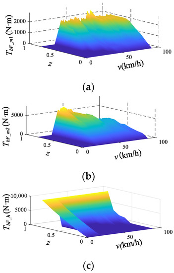
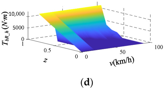
Figure 9.
Vehicle speed-braking intensity-braking torque distribution maps. (a) Motor 1 braking torque. (b) Motor 2 braking torque. (c) Front wheel hydraulic braking torque. (d) Rear wheel hydraulic braking torque.
Based on the maps of braking torque distribution obtained from the above optimization, the brake intensity of 0.3 and the initial vehicle speed of 90 km/h were selected for verification. As shown in Figure 10, compared to the rule-based regenerative braking strategy with motor 2 working first and then motor 1, the GA-RBD strategy enables both motors to participate in the braking process more evenly. As can be seen from Figure 11, the motor efficiency under the GA-RBD strategy moves towards the high efficiency zone benefiting from the genetic algorithm’s optimization for the dual motor operating point.
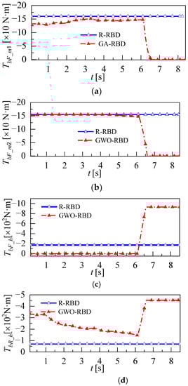
Figure 10.
Comparative graph of the different braking torque distribution strategies. (a) Motor 1 braking torque. (b) Motor 2 braking torque. (c) Front wheel hydraulic braking torque. (d) Rear wheel hydraulic braking torque.
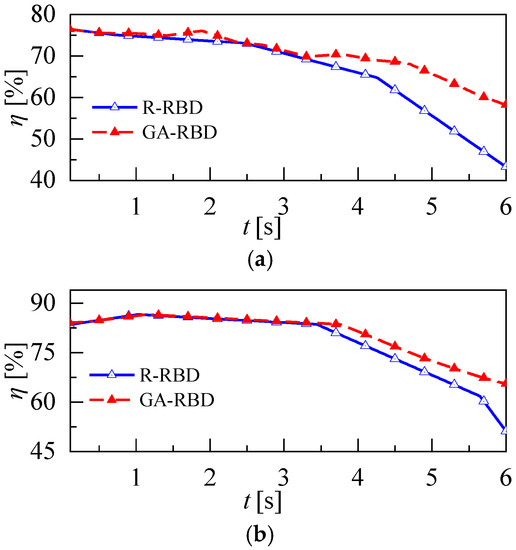
Figure 11.
Comparative graphs of motor efficiency under the different strategies. (a) Motor 1 efficiency. (b) Motor 2 efficiency.
The comparison of energy recovery and stability of the vehicle under different strategies is depicted in (a) and (b) of Figure 12, respectively. Compared to the rule-based method, energy recovery under the GA-RBD strategy (shown in Figure 12a) is improved by 16.3% and the root-mean-square value of the stability coefficient ε (shown in Figure 12b) is reduced by 4.5% (stability is improved).
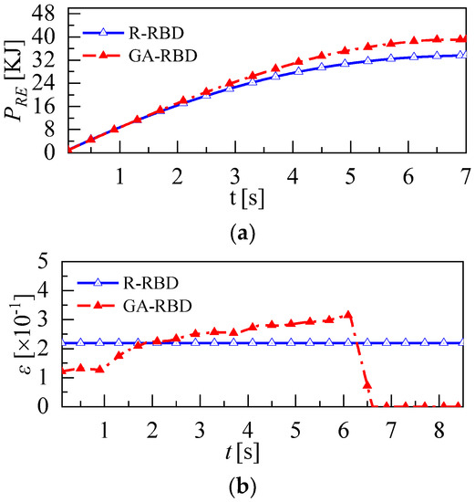
Figure 12.
Comparative graphs of energy recovery and stability under the different strategies. (a) Cumulative energy recovery. (b) Stability coefficient.
Where braking stability ε [13]: During braking, the situation with full use of the ground adhesion is defined as the ideal situation, therefore the deviation of the front- and rear-axle braking torque from the ideal braking torque is used to express braking stability. The symbol is denoted as ε.
In order to further verify the effectiveness of the two distribution strategies under different vehicle speeds and braking intensity operating conditions, the two strategies are compared and verified in Table 2. Under the braking intensity of 0.2 to 0.6 and vehicle speeds between 60 km/h and 90 km/h, the GA-RBD strategy improved the braking stability by a maximum of 5.4% compared to the rule method and the braking energy recovery improvement rate varied from 8.3% to 20.2% as the braking intensity and initial vehicle speed increased. The effectiveness of the GA-RBD strategy is further verified.
Table 2.
Results comparison under the different braking conditions.
5. Conclusions
This paper fully considered the structural characteristics of dual-motor EVs and established a regenerative braking strategy for dual-motor EVs that integrates energy recovery and braking stability, which further improves the regenerative braking energy recovery rate and braking stability. The main conclusions show the following:
(1) Based on the dual-motor EV architecture, an electric motor model, a power battery loss model and a vehicle longitudinal braking force model are established, and an energy recovery rate-dominated regenerative braking torque distribution rule considering the dual motors is designed.
(2) Based on the theory of genetic algorithm, a regenerative braking torque optimization method integrating energy recovery and braking stability is proposed, which considering SOC, vehicle speed and braking intensity. The braking intensity of 0.3 and the initial vehicle speed of 90 km/h are selected for validation. Compared with the rule-based method, the energy recovery and the stability under the GA-RBD strategy are improved by 22.8% and 4.8%.
(3) Various conditions were further selected for strategy validation and the results show that as vehicle speed increases and braking intensity increases, both the energy recovery rate and braking stability under the GA-RBD strategy are improved compared to the rule-based method.
In short, the proposed dual-motor EV regenerative braking that combines energy recovery and braking stability strategy can significantly improve the energy recovery rate and braking stability during braking, and can provide a theoretical reference for the EV in engineering practice. Considering the many uncertainties in real vehicle testing, the effectiveness of the GA-RED strategy could be tested on different types of real vehicles in future research.
Author Contributions
Conceptualization, T.W. and F.W.; methodology, P.Y.; software, T.W.; validation, F.W. All authors have read and agreed to the published version of the manuscript.
Funding
This research was funded by the National Natural Science Foundation of China [No. 52172358], Postdoctoral Science Foundation of China (No. 2022T150339), Project of Faculty of Agricultural Equipment of Jiangsu University [No. NZXB20210103].
Data Availability Statement
Not applicable.
Conflicts of Interest
The authors declare no conflict of interest.
References
- Fang, G.; Tian, L.; Fu, M.; Sun, M.; Du, R.; Lu, L. The effect of energy construction adjustment on the dynamical evolution of energy-saving and emission-reduction system in China. Appl. Energ. 2017, 196, 180–189. [Google Scholar] [CrossRef]
- Guo, J.; Dong, H.; Sheng, W.; Tu, C. Optimum control strategy of regenerative braking energy for electric vehicle. J. Jiangsu Univ. Nat. Sci. Ed. 2018, 39, 132–138. [Google Scholar]
- Ahmed, T.; Mehmet, F. An overview of regenerative braking systems. J. Energy Storage 2022, 52, 105033. [Google Scholar]
- Chen, L.; Zeng, L.; Pan, C.; Li, Z. Control of regenerative braking force for EV equipped with ultra-capacitor. J. Jiangsu Univ. Nat. Sci. Ed. 2014, 35, 508–512. [Google Scholar]
- He, R.; Li, M. Integrated control strategy of combined braking system and ABS based on road identification. J. Jiangsu Univ. Nat. Sci. Ed. 2020, 41, 20–26. [Google Scholar]
- Pennycott, A.; Novellis, L.D.; Gruber, P.; Sorniotti, A. Optimal braking force allocation for a four-wheel drive fully electric vehicle. J. Syst. Control Eng. 2014, 228, 621–628. [Google Scholar] [CrossRef]
- Pei, X.; Pan, H.; Chen, Z. Coordinated control strategy of electro-hydraulic braking for energy regeneration. Control Eng. Pract. 2020, 96, 104324. [Google Scholar] [CrossRef]
- Maia, R.; Silva, M.M.; Araújo, R.; Nunes, U. Electrical vehicle modeling: A fuzzy logic model for regenerative braking, Expert Systems with Applications. Expert. Syst. Appl. 2015, 42, 8504–8519. [Google Scholar] [CrossRef]
- Xu, W.; Chen, H.; Zhao, H.; Ren, B. Torque optimization control for electric vehicles with four in-wheel motors equipped with regenerative braking system. Mechatronics 2019, 57, 95–108. [Google Scholar] [CrossRef]
- Chen, X.; Wei, L.; Wang, X.; Li, L.; Wu, Q.; Xiao, L. Hierarchical cooperative control of anti-lock braking and energy regeneration for electromechanical brake-by-wire system. Mech. Syst. Signal Process. 2021, 159, 107796. [Google Scholar] [CrossRef]
- Banaei, A.; Alamatian, J.; Tohidi, R.Z. Active control of structures using genetic algorithm with dynamic weighting factors using in the constrained objective function. Structures 2022, 47, 189–200. [Google Scholar] [CrossRef]
- Wang, C. Research on Energy Management Strategy of Hybrid Electric Bus Based on Genetic Algorithm. Master’s Thesis, Shandong University, Jinan, China, 2020. [Google Scholar]
- Guo, H.; He, H.; Sun, X. Hierarchical optimization method for regenerative braking stability of hybrid electric vehicles. J. Beijing Inst. Technol. Engl. Ed. 2014, 23, 1–7. [Google Scholar]


Disclaimer/Publisher’s Note: The statements, opinions and data contained in all publications are solely those of the individual author(s) and contributor(s) and not of MDPI and/or the editor(s). MDPI and/or the editor(s) disclaim responsibility for any injury to people or property resulting from any ideas, methods, instructions or products referred to in the content. |
© 2023 by the authors. Licensee MDPI, Basel, Switzerland. This article is an open access article distributed under the terms and conditions of the Creative Commons Attribution (CC BY) license (https://creativecommons.org/licenses/by/4.0/).