Article

Neural Network PID-Based Preheating Control and Optimization for a Li-Ion Battery Module at Low Temperatures

1
College of Mechanical Engineering, University of Shanghai for Science and Technology, Shanghai 200093, China
2
State Key Laboratory of Automotive Safety and Energy, Tsinghua University, Beijing 100084, China
3
Clean Energy Automotive Engineering Center, Tongji University, Shanghai 201804, China
*
Authors to whom correspondence should be addressed.
World Electr. Veh. J. 2023, 14(4), 83; https://doi.org/10.3390/wevj14040083
Submission received: 15 February 2023 / Revised: 4 March 2023 / Accepted: 8 March 2023 / Published: 25 March 2023

Abstract

:
Low temperatures induce limited charging ability and lifespan in lithium-ion batteries, and may even cause accidents. Therefore, a reliable preheating strategy is needed to address this issue. This study proposes a low-temperature preheating strategy based on neural network PID control, considering temperature increase rate and consistency. In this strategy, electrothermal films are placed between cells for preheating; battery module areas are differentiated according to the convective heat transfer rate; a controller regulates heating power to control the maximum temperature difference during the preheating process; and a co-simulation model is established to verify the proposed warm-up strategy. The numerical calculation results indicate that the battery module can be preheated to the target temperature under different ambient temperatures and control targets. The coupling relationship between the preheating time and the maximum temperature difference during the preheating process is studied and multi-objective optimization is carried out based on the temperature increase rate and thermal uniformity. The optimal preheating strategy is proven to ensure the temperature increase rate and effectively suppress temperature inconsistency of the module during the preheating process. Although preheating time is extended by 17%, the temperature difference remains within the safety threshold, and the maximum temperature difference is reduced by 49.6%.

1. Introduction

A battery thermal management system (BTMS) is necessary for the safety and durability of a vehicle [1,2]. A battery module’s working performance and cycle life are affected by ambient temperature and inconsistent temperature of the batteries [3,4,5,6]. Specifically, when the working temperature of a battery is too high [7,8,9], it will lead to the loss of electrolytes and the separation of the electrode and the binder, causing irreversible damage to the battery. Conversely, lithium ions will deposit inside the battery when the operating temperature is too low, forming lithium dendrites [10,11], or internal resistance will increase, and charging will accelerate to the cut-off voltage [12,13,14]. At the same time, non-uniform temperature distribution of batteries will cause unbalanced electrical performance in the module, affecting an electric vehicle’s power system [15]. Therefore, the battery thermal management system must keep the battery module operating at a suitable temperature and reduce temperature inconsistency in the batteries.

1.1. Review of Battery Thermal Management Methods at Low Temperatures

A low-temperature environment leads to degradation of the cruising range of electric vehicles and reduction in charging efficiency [16,17]. Therefore, scholars have studied a variety of low-temperature preheating technologies for batteries. Low-temperature preheating technology is divided into internal and external preheating procedures [18]. The classification of preheating techniques proposed in this study is shown in Figure 1.
External preheating methods mainly include (a) thermal fluid preheating, (b) phase-change material (PCM) preheating, and (c) electrothermal element techniques. Thermal fluid preheating refers to heating air [19] or liquids [20,21,22], using the air or liquid as a medium, and then transferring heat into a power battery by heat exchange. PCM preheating [23,24] releases the stored heat in the process of converting to a solid state. An electrothermal film [25] is generally placed on the surface of the battery. The heat generated by the current flowing through the electrothermal film proceeds directly into the battery by thermal conduction. In Peltier-effect [26,27,28] preheating, current flows through the interface of two different conductors, and the heat is absorbed from the outside or released to the outside. Therefore, the hot end of a Peltier module can be used to realize the preheating function, and the intensity of preheating can be precisely controlled by adjusting the current level. Internal heating methods mainly include (d) SHLB (Self-heating lithium-ion batteries) preheating [29,30] and (e) current excitation techniques. In the internal preheating method, Joule heat is generated by current passing through a conductor with a resistance value to heat the battery. The conductor can be the battery. Depending on the positive and negative current flow, preheating methods are divided into DC (direct current) preheating [31,32], AC (alternating current) preheating [33,34], and pulse preheating [35]. The viscosity of the electrolyte inside the power battery increases at low temperatures, which hinders the movement of charge carriers, increasing the internal impedance of the power battery. The increased impedance at low temperatures brings a huge potential for heat generation to the battery. The conductor can also be a metal with high resistivity, such as nickel foil [29]. Self-heating techniques require a redesign of the cell structure to embed the nickel foil into the cell [30].
Hu et al. [23] conducted research on the current development status of low-temperature heating technology and concluded that internal heating of battery modules has the advantages of a fast temperature increase rate and good temperature consistency, but is problematic in terms of impact on battery life and safety of use. The heat transfer characteristics of a battery can be quantified when designing an external heating system. The main problem is poor temperature consistency within the module [36]. The electrothermal film preheating method can shorten the heat transfer path, reduce heat loss to the surrounding environment, and have high efficiency and low-cost characteristics. In practical scenarios, it is widely used by BTMS [35]. To study this preheating method, Zhang et al. [37] compared to the case where the electrothermal film is arranged on the side and bottom of the battery module. Under the same energy consumption, the side heating method has a faster temperature rise and better temperature consistency; Lei et al. [38] conducted simulation analysis by building a three-dimensional finite element model. By reducing the power of the heating element and setting the resting time during the heating process, the temperature consistency of the battery module can be improved. This method improved the temperature consistency. However, the preheating time should be shorter. Therefore, it is difficult for this preheating technology to overcome the temperature inconsistency in the battery module while ensuring the preheating rate. Chen et al. [39,40] proposed a double-direction liquid heating-based CTC battery module and a parallel liquid cooling system for the battery module. A multi-objective optimized design is carried out to improve the preheating efficiency considering the heating rate, thermal safety, thermal uniformity, and energy cost, which guides the balance of each technical factor for the thermal management of electric vehicles.

1.2. Motivation and Contributions of This Paper

Considering the need to balance reliability and economy in the practical application of BTMS, developing the electrothermal film preheating method is more meaningful. The most challenging problems in employing the electrothermal film preheating method are summarized as follows:
(1) How to solve the problem of the inconsistent battery module temperature caused by the electrothermal film in the actual use process?
(2) How to optimize the design of this preheating method to obtain a balance of performance indicators, such as temperature increase rate and maximum temperature difference, that are important for ensuring effective and safe preheating of batteries at low temperatures?
To overcome the challenges mentioned above, this study uses the neural network PID controller to regulate the preheating power and realizes the active control of the maximum temperature difference during the preheating process of the battery module. Further, the coupling relationship between the preheating time and the maximum temperature difference is studied. The multi-objective optimization of the temperature increase rate and distribution is based on the Pareto optimal theory. Finally, the verification results indicate that the preheating strategy can ensure the temperature increase rate of the module and effectively suppress the temperature inconsistency of each battery during the preheating process.

1.3. Paper Organization

The remainder of this paper is structured as follows. Section 2 introduces the preheating structure, modeling, and simulation analysis. Section 3 provides the design of the temperature balancing strategy and the simulation analysis, respectively. Section 4 proposes a scheme that takes into account the temperature uniformity and the temperature increase rate. Section 5 concludes the paper.

2. Preheating System and Simulation Analysis

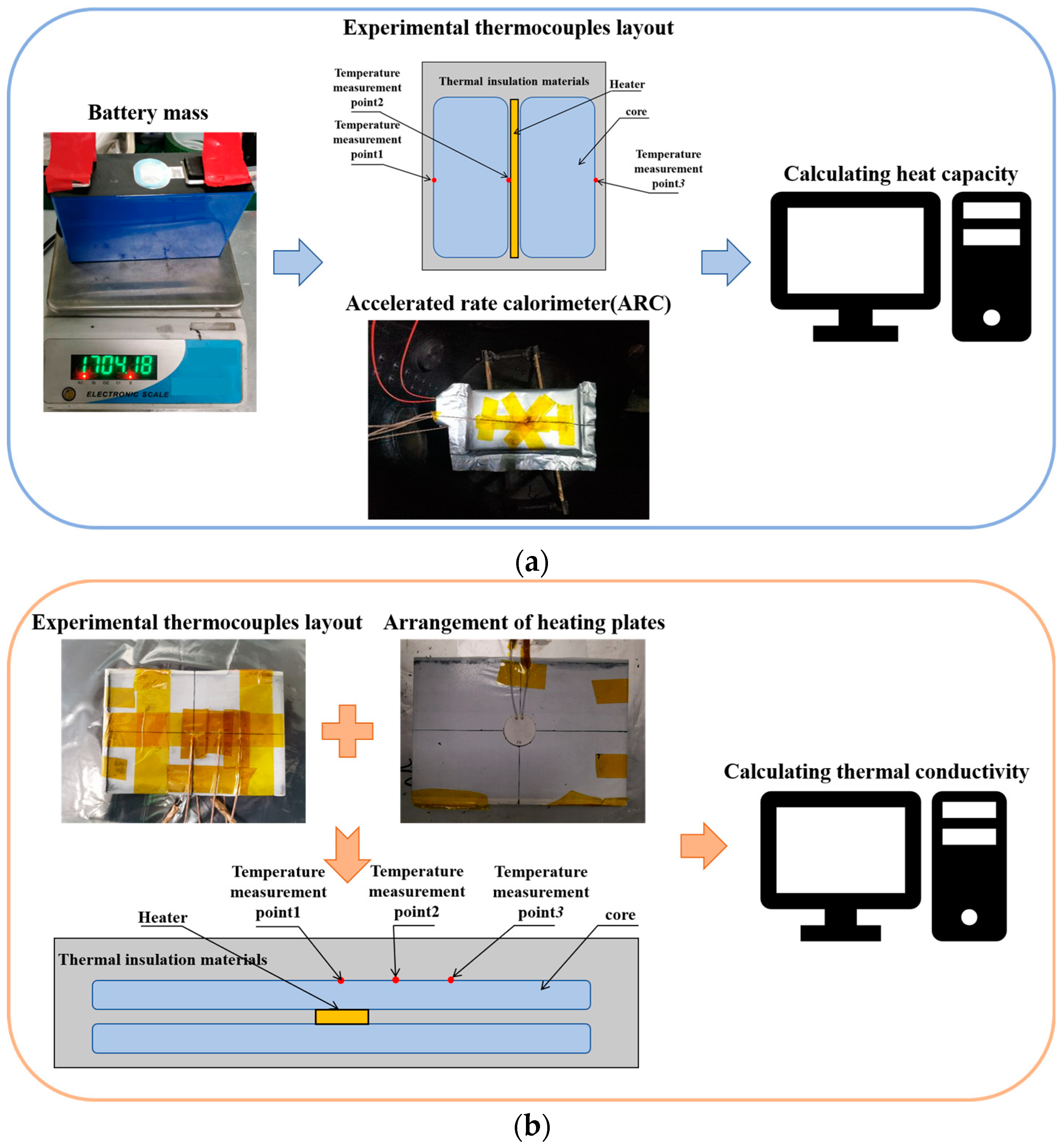
2.1. Experiment and Structure of the Preheating System

The battery cell tested is the 100 Ah nickel manganese cobalt oxide (NCM) prismatic lithium-ion battery (148 mm × 95 mm × 50 mm). The accuracy of the basic and thermal parameters of the cells provided important safeguards for subsequent studies of the modules, which were then followed by a set of experimental tests as shown in Figure 2. During the test, the cells are weighed and the thermocouples are arranged at different locations. An appropriate aluminum plastic film is prepared and sealed with a plastic sealant. In addition, a series of ARC setup preparations are performed to ensure that an adiabatic tracking test environment is provided such that the temperature within the cavity is always consistent with the temperature of the cell. Temperature rise and heat generation data are recorded, and the heat capacity is calculated as shown in Figure 2a. In order to measure the thermal conductivity of the cell in different directions, a ceramic heating plate is used for local heating to obtain temperature data of different parts of the cell. Local heating is performed in ARC using ceramic heating pads, as shown in Figure 2b, and three thermocouples are arranged outside the battery cell to monitor the temperature rise. The test consists of encapsulating the battery core with aluminum plastic film and wrapping it with insulation to prevent heat exchange with the environment. COMSOL is applied based on the test data to construct a 3D model for parameter sensitivity analysis and optimization identification, and identification parameters include core thermal conductivity and convective heat exchange coefficient. Table 1 shows the parameters obtained.
This research focuses on the temperature distribution and consistency of the battery modules under different temperature conditions. As shown in Figure 3, the battery module consists of six series and two parallel connected cells, resulting in a total of 12 cells. Electrothermal films are placed on the main surface of the batteries and are tightly arranged to form a battery module. Electrothermal film is mainly composed of polyimide film and the metal copper. The polyimide film with excellent electrical insulation and thermal conduction is selected as the thermal jacket. The metal copper is sandwiched between two polyimide film layers. The power needed for preheating the battery was determined by multiplying the maximum surface area of the battery with the upper limit of the power density range of the electrothermal film (0.4 W/cm2). Therefore, the preheater can be adjusted within the range of 0 to 56 W using the converter.

2.2. Grid Independence Test

Since mesh size is known to affect simulation results, while increasing the number of grid points is beneficial for improving the accuracy of the calculation, the calculation time increases accordingly [41]. To optimize simulation efficiency, a grid independence test was conducted using COMSOL Multiphysics 5.6 software (COMSOL Inc.; Stockholm, Sweden). Five mesh schemes were tested with mesh sizes of 30,173, 59,667, 93,251, 184,487, and 460,792, respectively. The battery module was preheated by the electrothermal film with a power of 56 W per heating element in a −30 °C environment for 2000 s, and the temperature of each battery was observed using domain probes. As shown in Figure 4, errors in temperature difference are negligible when the number of grids exceeds 184,487. Therefore, this study selected 184,487 as the base for the grid mesh of the battery module. Regarding the maximum temperature difference and maximum temperature in Figure 4, the maximum temperature difference refers to the difference in temperature between the hottest and coldest points on the battery module, while the maximum temperature refers to the highest temperature recorded on the battery module.

2.3. Numerical Model

During the preheating process, the battery module will not be charged and discharged; the heat balance equation can be expressed by Equation (1):
Q h = Q b a + Q f a ,
where  Q h  is the heat generated by the electrothermal film,  Q b a  is the heat absorbed by the battery,  Q f a  is the heat exchange between the battery and the environment.
During this period, the battery itself does not generate heat. The heat absorbed by the battery comes from the electrothermal film. Therefore, heat absorbed by the battery can be derived as follows:
Q b a = i n C m d T i d t .
In this study, we used 12 battery cells, where ‘n’ represents the number of cells, where  m  is the mass of the battery cell,  C  is the specific heat capacity of the battery,  T  is the temperature of the battery.
Convective heat transfer is considered in this study because the values of heat conduction and heat radiation are small and can be neglected. Heat convection is usually calculated using Newton’s formula, which can be calculated by Equation (3):
Q f a = i n h i S i T a m b i T i ,  
where  Q f a  is the heat dissipation,  h  is the heat transfer coefficient,  A  is the area,  T a m b  is the ambient temperature,  T  is the temperature of the battery; the n is 12 in this study.
Due to the complex internal structure and materials of the battery module, proper simplification is required.
(1) The density and specific heat capacity of cells are homogeneous;
(2) The battery has the same thermal conductivity in the same direction.
The electrothermal film transfers heat to the battery in the form of thermal conduction, and the unsteady heat conduction formula of the cell can be established as shown in Equation (4),
ρ C T t = λ x 2 T x 2 + λ x 2 T x 2 + λ x 2 T x 2 + q ,
where  q  is the heat generation rate,  λ  is the thermal conductivity,  ρ  is the density.

2.4. Simulation Analysis

The temperature target is of great significance to battery thermal management, which guides the design of a reasonable temperature threshold. Ref. [42] shows that when the average temperature of the battery pack is maintained at 20 °C, the total output energy of the battery pack is the greatest. Liu also shows that the total output energy of the battery module has an inflection point when the maximum temperature difference is 10 °C severely attenuated. Therefore, for battery thermal management in a low-temperature environment, the average temperature needs to reach 20 °C, and the maximum temperature difference within the module should be controlled within 10 °C.
A three-dimensional model of the battery module was constructed using COMSOL Multiphysics 5.6 finite element analysis software, and the model was meshed before solving. The ambient temperature was set to −30 °C and the power of each electrothermal film was kept at 56 W in order to preheat the battery module to an average temperature of 20 °C. The temperature cloud map of the side and upper section of the battery module is shown in Figure 5. There is a serious inconsistency in the temperature of the battery module; the maximum temperature difference reached 16.9 °C, which can severely hurt the performance of the module. The temperature distribution pattern, characterized by lower temperatures on both sides and higher temperatures in the middle area, can mainly be attributed to the outer battery’s large surface area, which is in direct contact with the air. This surface has a faster rate of convective heat transfer than the middle area, causing heat to be more easily lost.

3. Temperature Balancing Strategy and Result Analysis

3.1. Balancing Strategy

According to the analysis of simulation results in Section 2.3, the electrothermal film as a method of preheating the battery module causes a serious temperature inconsistency problem. Therefore, the following temperature balancing strategy is designed, as shown in Figure 6. Firstly, the battery module area should be differentiated. According to the area of the battery placed in the fluid, the two sides of the battery module are defined as the area with fast convection heat transfer, and the middle area of the module is defined as the area with slow heat transfer. Secondly, the controller regulates the power of electrothermal films to control the maximum temperature difference. The power of the inner-layer electrothermal film is feedback-controlled by the temperature difference between the inner-layer battery and the outer-layer battery, as well as the power of the sub-inner layer electrothermal films. The outer battery is in a fast convection heat exchange area, and heat is easily lost. Therefore, the outer-layer electrothermal film maintain the maximum power during the preheating process. Finally, the battery temperature difference control in the fast and slow regions of convective heat transfer is realized, and the battery module is not charged and discharged during the preheating process. The energy for the heater is supplied by external energy sources.

3.2. Neural Network PID Controller

PID control is a standard method in the field of control engineering. In practical applications, however, the controlled object often exhibits the characteristics of high nonlinearity, time-varying, and uncertainty, resulting in an unsatisfactory control effect. Since the relationship between proportional, integral and differential cooperate and constrain each other, there are infinitely many combinations in parameter tuning [43]. Neural network PID control with the capability of online learning to realize the optimal parameter combination can address the needs of temperature control in a complex and changing environment.
As shown in Figure 7, the PID neural network is a type of neural network that integrates PID control laws into the hidden layer, where PID neurons are used as activation functions with proportional, integral, and differential relationships. The network is continuously trained during forward and backward computation, modifying the connection weights between neurons to optimize the control performance of the system. When training the neural network, the first step is to initialize the network structure, including the number of nodes in the input layer (IN), the number of nodes in the hidden layer (H), and the number of nodes in the output layer (Out). Weight matrices (wi and wo) are then randomly initialized, and the back-propagation algorithm is used to update the weight matrices to minimize the difference between the control output of the network and the given reference signal. To speed up the convergence of the weights and ensure the stability of the control system, the momentum gradient update method is used to update the weight matrices. This method limits the output range and ensures that the control output of the network closely matches the reference signal. Overall, the PID neural network is an effective approach for implementing control systems that can adapt and optimize performance through continuous learning.
Using the incremental form of the PID control equation, the following Equations (5) and (6) can be obtained:
U k = U k 1 + K p e k e k 1 + K i e k + K d e k 2 e k 1 e k 2 ,
  e k = r k y k ,
where U(k) is the input of the system, Kp is the proportional adjustment parameter of PID, ki is the critical adjustment parameter of PID, Kd is the differential adjustment parameter of PID, e(k) is the difference between the expected output value of the system and the output value.
According to the system’s operation, through the self-adaptation of the neural network and the adjustment of the weighting coefficient, the three parameters output by the neural network correspond to the PID controller parameters of the optimal control law under the closed-loop logic.
A three-layer neural network is then adopted; the input of the input layer can be expressed in Equation (7):
O j 1 = x j , j = 1 , 2 , 3 .
The input and output of the hidden layer of the network can be derived as follows:
n e t i 2 k = j = 0 M w i j 2 O j 1 ,
O j 2 k = f n e t i 2 k , i = 1 , 2 , 3 ,
where  w i j 2  is the weighting coefficient of the hidden layer. The activation function of the neurons in the hidden layer is computed as the positive and negative symmetry of the Sigmoid function, given by the following equation:
f x = tanh x = e x e x e x + e x .
The input and output of the output layer can be expressed using the incremental form of the PID control equation, as shown in the following Equations (11) and (12):
n e t i 3 k = j = 0 Q w l i 3 O j 3 k ,
O l 3 k = g n e t i 3 k , l = 1 , 2 , 3 ,
O 1 3 k = K p ,
O 2 3 k = K i ,
O 3 3 k = K d .
The output nodes of the output layer correspond to three adjustable parameters  K p K i , and  K d , respectively. The activation function of the neurons in the output layer takes a non-negative Sigmiod function as Equation (13):
f x = 1 2 [ tanh x ] = e x e x + e x .
The performance indicator function is shown in Equation (14):
E k = 1 2 y d k y k 2 .
The weight coefficients are adjusted using the gradient descent method to produce the inertia equation for fast convergence of the search as Equation (15):
Δ w l i 3 k = η E K w l i 3 + α Δ w l i 3 k 1 ,
where η is the learning efficiency; α is the inertia coefficient.
Δ u k O 1 3 k = e k e k 1 , Δ u k O 2 3 k = e k , Δ u k O 3 3 k = e k 2 e k 1 + e k 2 .
Therefore, the neural network output layer weight learning algorithm can be expressed in Equations (13) and (14):
Δ w l i 3 k = α Δ w l i 3 k 1 + η δ l 3 O i 1 k ,
δ i 3 = e k s g n y k Δ u k Δ u k O 3 3 k g n e t l 3 k .
Hidden layer weighting coefficient learning algorithm expressed in Equations (19) and (20) denotes:
Δ w l i 2 k = α Δ w l i 2 k 1 + η δ l 2 O i 1 k ,
δ i 2 = f n e t l 3 k l = 1 3 δ l 3 w l i 3 k , i = 1 , 2 , 3 .
According to the preheating strategy formulated in this study, the COMSOL and Simulink co-simulation model is built, in which a battery module is constructed using the COMSOL Multiphysics 5.6 software and the controller is implemented using MATLAB and SIMULINK 2021a. The ambient temperature is selected as −30 °C, the battery module is preheated to an average temperature of 20 °C, and the maximum temperature difference is 10 °C as the control target for simulation. Figure 8 shows the change in temperature in each area. The battery module is preheated to an average temperature of 20 °C, and the total time is 2236 s. During the preheating process, the neural network PID controller is able to control the maximum temperature difference in the battery module. There is no evident overshoot, and the maximum overshoot is 0.4 °C. At the end of preheating, the maximum temperature difference is 9.95 °C, and the error from the expected value is 0.05 °C. Figure 9 shows the power of the electrothermal film and the controller parameter changes. The controller adaptively adjusts the parameter Kp, Ki, Kd according to the change in temperature difference during the process,, which in turn changes the power of the inner-layer and the sub-inner-layer electrothermal film. This is the key to the temperature difference being controlled to the desired value. The analyzed neural network is trained for the performance function, and the maximum number of times is set to 30 considering the practical situation. As shown in Figure 10, when time is 1000 s, the results show that the score decreases rapidly in the first five generations, indicating that the method has convergence and good performance.
In order to further explore the objective law of the strategy, the target control value of the maximum temperature difference between 0 and 10 °C is set for simulation under different ambient temperatures. Figure 11 shows that the preheating time increases as the ambient temperature decreases, which is obvious. At the same time, at the same ambient temperature, with the target control value of the maximum temperature difference increasing from 0 to 10 °C, the preheat time is gradually reduced. This is due to the fact that in the process of preheating to the average target temperature, as the target control value of the maximum temperature increases, the power of the inner layer and the sub-inner layer increases. Increasing the total power of the preheat system per unit time decreases the preheat time.

4. Multi-Objective Optimization

4.1. Optimization Principle

In this study, by setting the target control value of the maximum temperature difference, the goals of rapid preheating at low temperature and temperature-balancing preheating at low temperature can be met. When the target control value of the maximum temperature difference is set to the maximum allowable value of 10 °C, this is the shortest preheating time, which is primarily targeted at the fast-preheating pre-departure application scenario. The controller can maintain the temperature consistency of the battery module when the target control value of the maximum temperature difference is set to 0 °C. In practical application scenarios, however, both temperature-balancing and preheating rate must be considered. In the case of battery module preheating at low temperatures, the two subgoals of preheating rate and temperature-balancing are a pair of irreconcilable contradictions. In terms of how to consider the preheating rate and temperature-balancing, joint optimization is required. Multi-objective optimization is a reasonable and appropriate method for multiple contradictory objectives and finds an optimal method that achieves the optimal goal. With respect to multi-objective optimization indicators, the target preheating time in this study is a cost-type indicator. The shorter the heating time, the better, while the temperature balancing is an indicator of benefit type, that is, the higher the temperature balance, the better.
Combined with the simulation results, it can be known that when preheating at low temperature, the setting of the control target determines the maximum temperature difference and preheating time when preheating to the target average temperature. Furthermore, there is functional correspondence between the maximum temperature difference and the control target. According to Section 3.2, the error between the final control result and the expected value for the maximum temperature difference does not exceed 0.5 °C. Therefore, the sub-target temperature difference evaluation function is  y 1 x = x . For the preheating time at an ambient temperature of −30 °C, the relationship between it and the control target is fitted to a fifth-order function, so the evaluation function of the heating time is  y 2 x = 0.05865 x 5 1.653 x 4 + 16.59 x 3 62.43 x 2 108.1 x + 3652 . In addition, the two sub-goal evaluation functions refer to different objects. At the same time, the order of magnitude is very different. Therefore, this study adopts the standardization method of the range method to reconstruct the evaluation function  Y  of the sub-goal. The standardization Equation (21) denotes
Y i = y i y m i n y m a x y m i n , i M ,
where   y i  denotes the value of preheating time or temperature difference under the ith scheme, M is the set of all schemes,  Y i  is the normalized value in the range [0, 1], and the scale of normalization is chosen as the difference between the maximum and minimum value of this data value in the selected scheme. After the index is standardized, the closer the value is to 1, the better the effect, and the closer the value is to 0, the worse the effect. Therefore, after standardization, the objective function of the entire multi-objective optimization is to take the maximum value, calculated by Equation (22):
min u ,
where  u  is the objective function to be optimized. According to the importance of each sub-goal in the objective function, weight  Y i i = 1 , 2  is assigned to sub-goal  λ i i = 1 , 2 , the evaluation function is constructed by linear weighting. Then, the evaluation equation of the multi-objective optimization model is as follows:
u = λ 1 Y 1 + λ 2 Y 2 .
The objective function is constructed by the linear weighting method, that is, multiple objective functions are integrated into a single objective function through the linear weighting method, which transforms the problem into a general linear programming problem. In this study, we adopt the method of linear weighting, and the key to this is determining the weight of each indicator. We will now explore the determination of weight coefficients.

4.2. Weight Coefficient Determination

The key to the joint optimization of the linear weighting method is to determine the weight coefficient. The methods to determine the weight coefficient include the entropy weight method, fuzzy analytic hierarchy process (FAHP) [44], principal component analysis method (PVC) [45]. The entropy weight method can generally solve this problem [46]. To evaluate the index weight of problems, the method used in this study to determine the weight coefficient is the entropy weight method.
Table 2 shows the ambient temperature of −30 °C, along with the corresponding values of preheating time and temperature difference. Entropy weighting is a method for objectively determining weights, and the idea is to determine weights based on the amount of variation in the indicators. Thus, if an indicator’s information entropy is lower, it indicates that the indicator’s uncertainty is lower. Therefore, the more information is provided, the more meaningful the role should be in the overall assessment, and the greater the weight should be. In contrast, when an indicator’s information entropy is more prominent, indicating that the more prominent the uncertainty in the indicator, the less information provided, the smaller the role that should be played in the comprehensive evaluation, and the smaller the weight should be.
To calculate the weights of the two indicators simulated at −30 °C, the steps are described as follows:
(1) Data standardization
Calculated by Equation (21), the standardized data table can be obtained as shown in Table 3.
(2) The information entropy calculation of each indicator
The proportion of each data under all scenarios  p i  can be calculated by Equation (24):
p i = Q i i = 1 n Q i .
Then, the information entropy of each indicator can be calculated following Equation (25):
E i = 1 ln n i = 1 n p i ln p i .
The proportion of each data is shown in Table 4.
(3) Determination of the weight of each indicator
According to the calculated information entropy, the weight of each indicator can be derived as follows:
λ i = 1 E i k E i .
The process has two metrics, therefore k = 2, the weight of the preheating time  λ 1 = 0.57 , the weight of the temperature difference  λ 2 = 0.43 .

4.3. Optimization Solution

The evaluation equation of the multi-objective optimization model is  min u . Then, the target optimization problem is solved based on the genetic algorithm. The genetic algorithm uses population search technology to solve the population as a set of problems. It generates a new population generation by applying genetic operations such as selection, crossover, and mutation of similar biological, genetic, and environmental factors to the current population. It gradually optimizes the population to contain the states of the approximate optimal solution. The genetic algorithm toolbox is used in MATLAB to realize the Pareto optimal solution to the evaluation function  min u . The optimal solution obtained is 8.2 °C. When the control target is set to 8.2 °C, the temperature is preheated to the target average temperature of 20 °C at an ambient temperature of −30 °C. Moreover, the preheating speed and temperature balancing are both considered.
This study uses the ambient temperature of −30 °C and preheating to an average temperature of 20 °C as examples. The performance of the three preheating strategies is compared. One of the intermittent preheating strategies proposed in paper [38] proposes preheating for 0.1 s and stopping preheating for 0.3 s, which can effectively reduce the temperature difference. From Figure 12, it can be observed that different control strategies affect the power distribution in the preheating process, which in turn affects the preheating effect. Each electrothermal film is kept at 56 W during preheating without an optimal control strategy. Although its preheating time is the smallest among the three strategies, its maximum temperature reached 16.3 °C, far exceeding the safety threshold. The optimized control strategy is used compared to that. Although the preheating time was extended by 17%, the maximum temperature difference remained within the safety threshold, and the maximum temperature difference is reduced by 49.6%. Intermittent preheating is used. Although the maximum temperature difference is kept at 6.2 °C, the smallest among the three strategies, its preheating time reaches 9824 s. In comparison, the optimized control strategy of the maximum temperature difference is expanded by 32%, but its preheating time is reduced by 75.3%. It is visible, and the preheating speed is greatly improved.

5. Conclusions

In this study, a preheating strategy is proposed that is suitable for different ambient temperatures and can actively control the maximum temperature difference in the battery module. The first step is to divide the area of the battery module according to the convective heat transfer rate, and the power of the heater element in the module is feedback controlled by the temperature difference of each layer of the battery in order to realize the control of the maximum temperature difference within the module. Then, combined with the neural network PID controller and the online learning ability to achieve the optimal parameters. Finally, we investigate the coupling relationship between preheating time and maximum temperature difference in the process. The Pareto-optimal solution of the constructed valuation function is achieved using the genetic algorithm. The proposed low-temperature preheating strategy, based on the optimized control objective, can effectively suppress the temperature inconsistency in the module during the preheating process to ensure the rate of temperature rise. We use the optimized control strategy compared to without this. The results show that although the preheating time is extended by 17%, the maximum temperature difference remained within the safety threshold, and the maximum temperature difference is decreased by 49.6%. Intermittent preheating is applied. The maximum temperature difference is maintained at 6.2 °C, the lowest of the three strategies, but its preheating time reached 9824 s. In comparison, while the optimized maximum temperature difference control strategy is extended by 32%, its preheating time was reduced by 75.3%. Future research will focus on extending the cruising range of electric vehicles based on post-departure path planning and battery pack status at the time of departure.

Author Contributions

Conceptualization, Y.Z., L.L., K.S. and S.C.; Software, S.P.; Validation, S.P.; Data curation, S.P.; Writing—original draft, S.P.; Writing—review and editing, S.C.; Supervision, Y.Z., L.L. and S.C.; Funding acquisition, Y.Z. All authors have read and agreed to the published version of the manuscript.

Funding

This research is supported National Natural Science Foundation of China (NSFC) under the Grant number of 52277222, Shanghai Science and Technology Development Fund 22ZR1444500.

Data Availability Statement

Not applicable.

Conflicts of Interest

The authors declare no conflict of interest.

References

  1. Qin, P.; Sun, J.; Yang, X.; Wang, Q. Battery thermal management system based on the forced-air convection: A review. Etransportation 2021, 7, 100097. [Google Scholar] [CrossRef]
  2. Gehringer, D.; Kuthada, T.; Wagner, A. Thermal Management System of the UNICARagil Vehicles—A Comprehensive Overview. World Electr. Veh. J. 2023, 14, 6. [Google Scholar] [CrossRef]
  3. Kizilel, R.; Sabbah, R.; Selman, J.R.; Al-Hallaj, S. An alternative cooling system to enhance the safety of Li-ion battery packs. J. Power Sources 2009, 194, 1105–1112. [Google Scholar] [CrossRef]
  4. Pesaran, A.A.J.B.M. Battery thermal management in EV and HEVs: Issues and solutions. In Proceedings of the Advanced Automotive Battery Conference, Las Vegas, NV, USA, 6–8 February 2001. [Google Scholar]
  5. Pesaran, A.A.; Vlahinos, A.; Burch, S. Thermal Performance of EV and HEV Battery Modules and Packs; National Renewable Energy Laboratory: Golden, CO, USA, 1997. [Google Scholar]
  6. Yang, H.; Wang, P.; An, Y.; Shi, C.; Sun, X.; Wang, K.; Zhang, X.; Wei, T.; Ma, Y. Remaining useful life prediction based on denoising technique and deep neural network for lithium-ion capacitors. Etransportation 2020, 5, 100078. [Google Scholar] [CrossRef]
  7. Han, X.; Lu, L.; Zheng, Y.; Feng, X.; Li, Z.; Li, J.; Ouyang, M. A review on the key issues of the lithium ion battery degradation among the whole life cycle. Etransportation 2019, 1, 100005. [Google Scholar] [CrossRef]
  8. Dondelewski, O.; O’Connor, T.S.; Zhao, Y.; Hunt, I.A.; Holland, A.; Hales, A.; Offer, G.J.; Patel, Y. The role of cell geometry when selecting tab or surface cooling to minimise cell degradation. Etransportation 2020, 5, 100073. [Google Scholar] [CrossRef]
  9. Hales, A.; Prosser, R.; Diaz, L.B.; White, G.; Patel, Y.; Offer, G. The Cell Cooling Coefficient as a design tool to optimise thermal management of lithium-ion cells in battery packs. Etransportation 2020, 6, 100089. [Google Scholar] [CrossRef]
  10. Piao, N.; Gao, X.; Yang, H.; Guo, Z.; Hu, G.; Cheng, H.-M.; Li, F. Challenges and development of lithium-ion batteries for low temperature environments. Etransportation 2022, 11, 100145. [Google Scholar] [CrossRef]
  11. Li, Z.; Huang, J.; Liaw, B.Y.; Metzler, V.; Zhang, J. A review of lithium deposition in lithium-ion and lithium metal secondary batteries. J. Power Sources 2014, 254, 168–182. [Google Scholar] [CrossRef]
  12. Jaguemont, J.; Boulon, L.; Dubé, Y. A comprehensive review of lithium-ion batteries used in hybrid and electric vehicles at cold temperatures. Appl. Energy 2016, 164, 99–114. [Google Scholar] [CrossRef]
  13. Ouyang, M.; Chu, Z.; Lu, L.; Li, J.; Han, X.; Feng, X.; Liu, G. Low temperature aging mechanism identification and lithium deposition in a large format lithium iron phosphate battery for different charge profiles. J. Power Sources 2015, 286, 309–320. [Google Scholar] [CrossRef]
  14. Liu, H.; Wei, Z.; He, W.; Zhao, J. Thermal issues about Li-ion batteries and recent progress in battery thermal management systems: A review. Energy Convers. Manag. 2017, 150, 304–330. [Google Scholar] [CrossRef]
  15. Pesaran, A.A. Battery thermal models for hybrid vehicle simulations. J. Power Sources 2002, 110, 377–382. [Google Scholar] [CrossRef]
  16. Du, J.; Liu, Y.; Mo, X.; Li, Y.; Li, J.; Wu, X.; Ouyang, M. Impact of high-power charging on the durability and safety of lithium batteries used in long-range battery electric vehicles. Appl. Energy 2019, 255, 113793. [Google Scholar] [CrossRef]
  17. Tomaszewska, A.; Chu, Z.; Feng, X.; O’Kane, S.; Liu, X.; Chen, J.; Ji, C.; Endler, E.; Li, R.; Liu, L.; et al. Lithium-ion battery fast charging: A review. eTransportation 2019, 1, 100011. [Google Scholar] [CrossRef]
  18. Wu, S.; Xiong, R.; Li, H.; Nian, V.; Ma, S. The state of the art on preheating lithium-ion batteries in cold weather. J. Energy Storage 2019, 27, 101059. [Google Scholar] [CrossRef]
  19. Teng, H.; Ma, Y.; Yeow, K.; Thelliez, M. An Analysis of a Lithium-ion Battery System with Indirect Air Cooling and Warm-Up. SAE Int. J. Passeng. Cars-Mech. Syst. 2011, 4, 1343–1357. [Google Scholar] [CrossRef]
  20. Liu, Z.; Liu, X.; Meng, H.; Guo, L.; Zhang, Z. Numerical analysis of the thermal performance of a liquid cooling battery module based on the gradient ratio flow velocity and gradient increment tube diameter. Int. J. Heat Mass Transf. 2021, 175, 121338. [Google Scholar] [CrossRef]
  21. Lee, D.-Y.; Cho, C.-W.; Won, J.-P.; Park, Y.C.; Lee, M.-Y. Performance characteristics of mobile heat pump for a large passenger electric vehicle. Appl. Therm. Eng. 2013, 50, 660–669. [Google Scholar] [CrossRef]
  22. Zhang, C.; Huang, J.; Sun, W.; Xu, X.; Li, Y. Research on the Influence of Liquid on Heat Dissipation and Heating Characteristics of Lithium-Ion Battery Thermal Management System. World Electr. Veh. J. 2022, 13, 68. [Google Scholar] [CrossRef]
  23. Hu, X.; Zheng, Y.; Howey, D.A.; Perez, H.; Foley, A.; Pecht, M. Battery warm-up methodologies at subzero temperatures for automotive applications: Recent advances and perspectives. Prog. Energy Combust. Sci. 2020, 77, 100806. [Google Scholar] [CrossRef]
  24. Salunkhe, P.B.; Shembekar, P.S. A review on effect of phase change material encapsulation on the thermal performance of a system. Renew. Sustain. Energy Rev. 2012, 16, 5603–5616. [Google Scholar] [CrossRef]
  25. Huang, D.; Chen, Z.; Zhou, S. Model prediction-based battery-powered heating method for series-connected lithium-ion battery pack working at extremely cold temperatures. Energy 2021, 216, 119236. [Google Scholar] [CrossRef]
  26. Moria, H.; Pourhedayat, S.; Dizaji, H.S.; Abusorrah, A.M.; Abu-Hamdeh, N.H.; Wae-Hayee, M. Exergoeconomic analysis of a Peltier effect air cooler using experimental data. Appl. Therm. Eng. 2021, 186, 116513. [Google Scholar] [CrossRef]
  27. Harmon, T.; Cahn, J.; Logan, M. Measurement of Thermal Conductivity by Utilization of the Peltier Effect. J. Appl. Phys. 1959, 30, 1351–1359. [Google Scholar] [CrossRef]
  28. Enescu, D.; Virjoghe, E.O. A review on thermoelectric cooling parameters and performance. Renew. Sustain. Energy Rev. 2014, 38, 903–916. [Google Scholar] [CrossRef]
  29. Yang, X.-G.; Liu, T.; Wang, C.-Y. Innovative heating of large-size automotive Li-ion cells. J. Power Sources 2017, 342, 598–604. [Google Scholar] [CrossRef]
  30. Zhang, G.; Ge, S.; Xu, T.; Yang, X.-G.; Tian, H.; Wang, C.-Y. Rapid self-heating and internal temperature sensing of lithium-ion batteries at low temperatures. Electrochim. Acta 2016, 218, 149–155. [Google Scholar] [CrossRef]
  31. Ning, G.; Haran, B.; Popov, B.N. Capacity fade study of lithium-ion batteries cycled at high discharge rates. J. Power Sources 2003, 117, 160–169. [Google Scholar] [CrossRef]
  32. Ruan, H.; Jiang, J.; Sun, B.; Su, X.; He, X.; Zhao, K. An optimal internal-heating strategy for lithium-ion batteries at low temperature considering both heating time and lifetime reduction. Appl. Energy 2019, 256, 113797. [Google Scholar] [CrossRef]
  33. Stuart, T.; Hande, A. HEV battery heating using AC currents. J. Power Sources 2004, 129, 368–378. [Google Scholar] [CrossRef]
  34. Zhang, J.; Ge, H.; Li, Z.; Ding, Z. Internal heating of lithium-ion batteries using alternating current based on the heat generation model in frequency domain. J. Power Sources 2015, 273, 1030–1037. [Google Scholar] [CrossRef]
  35. Qin, Y.; Du, J.; Lu, L.; Gao, M.; Haase, F.; Li, J.; Ouyang, M. A rapid lithium-ion battery heating method based on bidirectional pulsed current: Heating effect and impact on battery life. Appl. Energy 2020, 280, 115957. [Google Scholar] [CrossRef]
  36. Wang, Y.; Zhang, X.; Chen, Z. Low temperature preheating techniques for Lithium-ion batteries: Recent advances and future challenges. Appl. Energy 2022, 313, 118832. [Google Scholar] [CrossRef]
  37. Zhang, J.; Sun, F.; Wang, Z. Heating Character of a LiMn2O4 Battery Pack at Low Temperature Based on PTC and Metallic Resistance Material. Energy Procedia 2017, 105, 2131–2138. [Google Scholar] [CrossRef]
  38. Lei, Z.; Zhang, Y.; Lei, X. Improving temperature uniformity of a lithium-ion battery by intermittent heating method in cold climate. Int. J. Heat Mass Transf. 2018, 121, 275–281. [Google Scholar] [CrossRef]
  39. Chen, S.; Zhang, G.; Wu, C.; Huang, W.; Xu, C.; Jin, C.; Wu, Y.; Jiang, Z.; Dai, H.; Feng, X.; et al. Multi-objective optimization design for a double-direction liquid heating system-based Cell-to-Chassis battery module. Int. J. Heat Mass Transf. 2022, 183, 122184. [Google Scholar] [CrossRef]
  40. Chen, S.; Zhang, G.; Zhu, J.; Feng, X.; Wei, X.; Ouyang, M.; Dai, H. Multi-objective optimization design and experimental investigation for a parallel liquid cooling-based Lithium-ion battery module under fast charging. Appl. Therm. Eng. 2022, 211, 118503. [Google Scholar] [CrossRef]
  41. Xie, B.; Zhang, G.; Jiang, Y.; Wang, R.; Sheng, X.; Xi, F.; Zhao, Z.; Chen, W.; Zhu, Y.; Wang, Y.; et al. “3D+1D” modeling approach toward large-scale PEM fuel cell simulation and partitioned optimization study on flow field. Etransportation 2020, 6, 100090. [Google Scholar] [CrossRef]
  42. Liu, Z. Simulation of Cell to Cell Variations and Thermal Management in Lithium-Ion Battery Packs; Tianjin University: Tianjin, China, 2014. [Google Scholar]
  43. Kang, J.; Meng, W.; Abraham, A.; Liu, H. An adaptive PID neural network for complex nonlinear system control. Neurocomputing 2014, 135, 79–85. [Google Scholar] [CrossRef] [Green Version]
  44. Chao, R.-J.; Chen, Y.-H. Evaluation of the criteria and effectiveness of distance e-learning with consistent fuzzy preference relations. Expert Syst. Appl. 2009, 36, 10657–10662. [Google Scholar] [CrossRef]
  45. Lam, K.C.; Hu, T.S.; Ng, S.T. Using the principal component analysis method as a tool in contractor pre-qualification. Constr. Manag. Econ. 2005, 23, 673–684. [Google Scholar] [CrossRef]
  46. Huang, J. Combining entropy weight and TOPSIS method for information system selection. In 2008 IEEE Conference on Cybernetics and Intelligent Systems; IEEE: New York, NY, USA, 2008; pp. 1281–1284. [Google Scholar] [CrossRef]
Figure 1. Classification of preheating techniques for lithium-ion batteries.
Wevj 14 00083 g001
Figure 2. Basic test and experimental system. (a) Heat capacity test. (b) Thermal conductivity test.
Wevj 14 00083 g002
Figure 3. Structure of the preheating system.
Wevj 14 00083 g003
Figure 4. Grid independence test.
Wevj 14 00083 g004
Figure 5. The temperature distribution of the battery module when the average temperature is preheated to 20 °C.
Wevj 14 00083 g005
Figure 6. Area division diagram.
Wevj 14 00083 g006
Figure 7. Neural network PID controller structure.
Wevj 14 00083 g007
Figure 8. Temperature difference change in the module.
Wevj 14 00083 g008
Figure 9. Controller performance.
Wevj 14 00083 g009
Figure 10. Convergence trajectory of the performance function.
Wevj 14 00083 g010
Figure 11. The required preheating time when heating to an average temperature of 20 °C under different ambient temperatures and control objectives.
Wevj 14 00083 g011
Figure 12. Comparison of the results of different preheating strategies.
Wevj 14 00083 g012
Table 1. Physical parameters.
ItemsValue
Working voltage2.5~4.2 V
Nominal capacity101.2 Ah
Heat capacity1001.8 J/Kg/°C
Various thermal conductivity22.4 W/(m·K) (x direction)
22.4 W/(m·K) (y direction)
1.15 W/(m·K) (z direction)
Battery density2418.2 Kg/m3
Battery mass1.7 Kg
Table 2. The value of preheating time and temperature difference at the ambient temperature of −30 °C.
Preheating Time (s)Temperature Difference (°C)
36600
34651
33302
30903
29104
27755
26406
25657
24458
23259
223610
Table 3. Standardized value of preheating time and temperature difference.
  Standardized   Preheating   Time   Q t   Standardized   Temperature   Difference   Q Δ
10
0.8602150.1
0.7634410.2
0.5913980.3
0.4623660.4
0.3655910.5
0.2688170.6
0.2150540.7
0.1290320.8
0.0430110.9
01
Table 4. The proportion of preheating time and temperature difference occupied.
  Calculate   the   Proportion   of   Preheating   Time   p t   Calculate   the   Proportion   of   Temperature   Difference   p Δ
0.1830244680
0.1624342550.018083183
0.1258293620.036166365
0.0983757450.054249548
0.0777853190.072332731
0.0571951060.090415913
0.045756170.108499096
0.0274536170.126582278
0.0091512770.144665461
00.162748644
10
Disclaimer/Publisher’s Note: The statements, opinions and data contained in all publications are solely those of the individual author(s) and contributor(s) and not of MDPI and/or the editor(s). MDPI and/or the editor(s) disclaim responsibility for any injury to people or property resulting from any ideas, methods, instructions or products referred to in the content.

