Abstract
This paper offers a novel dual-mode double stator wound rotor synchronous machine for variable speed applications. The proposed motor integrates the benefits of both the traditional wound rotor synchronous machine (WRSM) and brushless wound rotor synchronous machine (BL-WRSM). A constant torque can be attained in the maximum torque per ampere region by operating the proposed machine as a traditional WRSM in Mode I, and a constant power can be attained in the field-weakening region by operating it as a BL-WRSM in Mode II. Moreover, due to the dual-stator structure, the proposed machine exhibits improved performance in terms of high torque density as compared to the existing single stator BL-WRSM. By using a special stator winding arrangement to achieve the sub-harmonic component of the stator magnetomotive force, the brushless operation of the proposed machine is achieved. The additional sub-harmonic component induces a voltage in the harmonic winding placed on the rotor, which is then rectified and provided a DC current to field winding for brushless excitation. In order to validate the effectiveness of the proposed machine, a two-dimensional finite element analysis (FEA) is carried out.
1. Introduction
Electric vehicles (EV) and hybrid electric vehicles (HEV) have been established to mitigate environmental apprehensions. For such operations, permanent-magnet (PM) synchronous machines (PMSM) are used as a result of their robust structure, high torque density, and high power density, and they are not bound to an external excitation system [1,2,3,4]. However, the problem with these vehicles using PM machines lies in their expensive price, which is primarily attributed to the scarcity and rising price of permanent magnet materials. [5]. Consequently, the demand for alternative solutions, such as wound rotor synchronous machines (WRSM), has increased to overcome the high cost issue with permanent magnet synchronous machines [6]. For EV and HEV application, various machine topologies, such as PM synchronous machines, wound rotor synchronous machines (WRSM), and the induction machine (IM), have been studied in [7]. Moreover, magnet-less electrical motors, such as IM and WRSM, are presented as practical alternatives to the motors containing the rare earth-magnet. Nonetheless, there are some issues related to the conventional WRSM, including sparking across the brush and slip-rings assembly, losses, as well as maintenance cost issues, which are mainly due to the existence of slip-ring and brushes assembly.
Thus, for single stator WRSMs, numerous brushless topologies have been proposed in recent years. In [8], a brushless topology for WRSM that used the sub-harmonic part of stator magneto-motive force (MMF) was introduced. This brushless topology utilized two inverters in order to energize the stator winding for the brushless functioning of WRSM. The utilization of two inverters makes the aforementioned brushless topology less appropriate for the applications requiring a practical approach. Moreover, this machine exhibits low torque in the constant torque area. To overcome this disadvantage of low torque, a permanent magnet-assisted brushless WRSM was presented in [9].
Several brushless topologies for WRSM were presented in [10,11,12,13,14] by using the third-harmonic parts of the stator magneto-motive force (MMF) in order to produce the voltage required to energize the harmonic winding placed on the rotor along with the field winding. In order to create the rotor flux, the induced voltage had been rectified and provided a direct current (DC) to the field winding to run WRSM as a brushless machine.
A brushless topology for WRSM that utilizes the third-harmonic contribution of the stator MMF was introduced in [10]. This brushless topology employs a three-phase stator winding, which is connected in parallel with thyristor switches. The thyristor switches were turned on and off during positive and negative half cycles to create an additional third-harmonic current pulsating in the stator winding. This additional current is further utilized for the brushless operation. This brushless machine exhibits a high torque ripple due to the switching of the thyristor switches and irregular structure of the rotor, which was a requirement for the validation of this brushless topology.
A harmonic current field excitation technique was proposed in [11] for a wound rotor synchronous machine by controlling the time-harmonic magneto-motive force. Two inverters connected to the stator winding induce a third-harmonic current component, creating a varying magnetic field that generates a rotor field. In [12], a novel single inverter brushless topology is presented that generates an additional third-harmonic component to achieve brushless operation in a wound field synchronous machine. Using a single inverter with modified third-harmonic injection, it optimizes the usage of the third-harmonic component for improved performance.
In [13,14], the researcher introduces an electrically excited brushless synchronous machine with additional harmonic field windings in its rotor structure. By utilizing stator harmonic windings to create spatially distributed third-harmonic magnetic fields, the machine achieves brushless electrical excitation. The study analyzes harmonic windings, magnetic fields, and mutual interference using finite element methods, and experimental results validate its effectiveness.
A single inverter brushless topology was presented for the WRSM in [15], where the sub-harmonic component had been produced by means of a specialized stator winding. The schematic diagram of this brushless topology is shown in Figure 1. This additional harmonic component was used to induce a voltage in the harmonic winding located on the rotor for the brushless excitation of the WRSM. However, the asymmetrical number of turns in the stator windings results in a low slot fill factor in stator slots with a lower number of turns. Therefore, this machine exhibits the issues relating to the lower utilization of the machine’s material. Moreover, due to the brushless operation, the starting torque of the machine is very low.
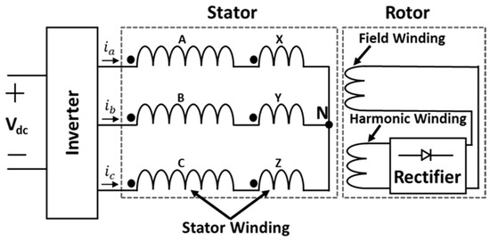
Figure 1.
Existing brushless WRSM topology [15].
To overcome the issue of asymmetrical stator winding and the low slot fill factor, in half of the stator slots winding in [15], a novel brushless topology utilizing a sub-harmonic component for rotor field winding excitation was proposed in [16]. In this brushless topology, stator winding was divided into four coils, each of which carries an equal number of turns. Among these four coils, two coils were connected in parallel, due to which the current was divided in each phase of stator winding. This brushless topology utilizes a single three-phase inverter to supply the stator winding. The special winding arrangement makes it possible to create an additional harmonic component in the airgap to induce the voltages on the harmonic winding placed on the rotor, which is further utilized for the brushless operation of the wound field synchronous machine.
To overcome the issue of a high torque ripple, the single inverter BL-WRSM presented in [15] was optimized and experimentally validated in [17]. Moreover, wide speed range analysis was also performed to check the validity of such brushless machines for high-speed applications. In [18], a permanent assisted hybrid BL-WRSM was presented. Because of the presence of permanent magnets, the issue of a low starting torque was resolved in this research. Although this hybrid brushless topology could not achieve a constant torque under base speed, the starting torque was improved. To reduce permanent magnet utilization, the consequent-pole structure was utilized.
The conventional WRSM was presented as an alternative to the permanent magnet synchronous machine for traction applications in [19]. In this research, a traditional WRSM was designed and its performance was analyzed in comparison to the interior permanent magnet synchronous machine utilized in Toyota Prius 2010. In [20], a novel dual-mode wound rotor synchronous machine (DWRSM) combined the advantages of CWRSM and BWRSM. Mode I achieves a constant torque, operating as a CWRSM, while Mode II achieves constant power in the field-weakening region as a BWRSM. Validation through FEA and a prototype experiment confirms the effectiveness of this approach, including transients during mode changes.
In the aforementioned designs that eliminate the need for brushes, the stator current is the lone cause for the process of supplying necessary electrical energy to generate the magnetic field, and the current flowing through the field winding is produced by the harmonic constituent of the MMF. During the operation of brushless WRSM (BL-WRSM) in the persistent-torque area, the voltage induced in the harmonic winding varies as the speed of the machine varies, resulting in the steady increase in the field current along with the increasing speed of the machine. Thus, the torque within a constant torque region cannot be kept constant by the operating WRSMs in the brushless mode. Nevertheless, these machines operate well at or above the rated speed. This indicates that while these BL-WRSMs are appropriate exclusive to their rated speed or beyond, they cannot be applied to variable-speed applications.
This paper presents a dual-mode dual-stator wound rotor synchronous machine (DMDS-WRSM) as a potential solution for variable speed applications, which overcomes low torque issues in the aforementioned brushless machines. Constant power and a constant torque have been attained in the constant torque and constant power regions, respectively, through the dual-mode machine operation. Moreover, the dual-stator design of the proposed DMDS-WRSM results in an improved torque density. In order to certify the effectiveness of the anticipated DMDS-WRSM, the process of conducting a two-dimensional finite element analysis (FEA) is performed using Electromagnetic transient solver ANSYS Maxwell. Ultimately, the performance of the suggested machine has been compared and correlated with that of a single-stator BL-WRSM.
2. Proposed Dual-Mode Dual-Stator Brushless Topology and Operating Principle
2.1. Proposed Dual-Mode Dual-Stator Brushless Topology
Based upon the currently used brushless topology illustrated in Figure 1 [12], the proposed DMDS-WRSM is designed to overcome the issue of a low starting torque below base speed. Moreover, due to the dual-stator structure, the proposed DMDS-WRSM exhibits high torque density compared to the currently used single-inverter brushless topology. The proposed DMDS-WRSM presents a WRSM, which can generate a constant torque that lies below the base speed by operating as a conventional brushed WRSM, and exhibits constant power beyond the base speed by working as BL-WRSM. The suggested dual-mode dual-stator topology is displayed in Figure 2.
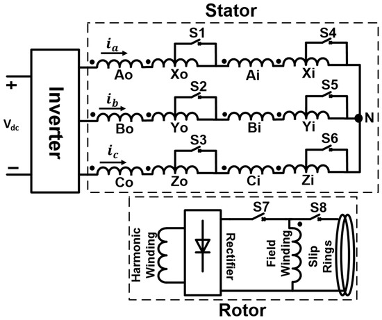
Figure 2.
Proposed dual-mode dual-stator topology.
The dual-stator design is utilized to enhance the torque density, as considered in [13]. The three-phase winding of each stator is distributed in two sets of windings: winding ABC and a centrally tapped winding XYZ, where “O” symbolizes the outer stator and “I” symbolizes the inner stator. Both windings are interconnected in series and possess an identical number of turns. The inner and outer stator windings are series-connected, and a three-phase current is provided to the stator winding through a single inverter. To enable the dual-mode operation of the suggested machine, switches are used to tap the center point of winding XYZ in each stator.
The rotor of the proposed machine involves two distinct windings: the harmonic winding and the field winding. These windings are interconnected, and the connection involves the utilization of a bridge rectifier, which is positioned on the outer edge of the rotor. The harmonic winding is responsible for inducing the voltage needed to excite the rotor field winding during the brushless mode of operation. As for the field winding, the harmonic winding is linked in parallel with the field winding using a bridge rectifier placed on the rotor periphery. Additionally, the brushes are connected to the field winding along with slip-ring assembly through external switches for the Mode II operation of the proposed machine.
2.2. Operating Principle
As discussed earlier, the proposed brushless DMDS-WRSM operates in two operational modes. The schematic diagrams of Mode I and Mode II are shown in Figure 3a and Figure 3b, respectively.
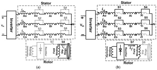
Figure 3.
The proposed topology’s modes of operation: (a) Mode I: constant torque operation; (b) Mode II: constant power operation.
2.2.1. Mode I: Constant Torque Operation
The suggested topology offers two distinct modes of operation, with Mode I being one of them, as shown in Figure 3a. Switches S1–S7 are kept opened in this mode, and the proposed topology enables the supply of a three-phase sinusoidal current to the stator winding by employing the inverter. The supplied three-phase balanced sinusoidal currents are given in Equations (1)–(3). Switch S8 is closed to connect the field winding to the exterior DC supply. During this mode, the proposed topology functions as a conventional brushed wound rotor synchronous machine (WRSM). In this mode, the proposed machine achieves a constant torque in the constant torque region as in a conventional WRSM drive.
where is the maximum current supplied to the stator winding, represents the angular frequency, and is the time.
Due to the full pitched distributed winding configuration and the equal number of turns for both windings in Mode I of the proposed machine, the winding functions can be exhibited as a rectangular wave, as shown in Figure 4.
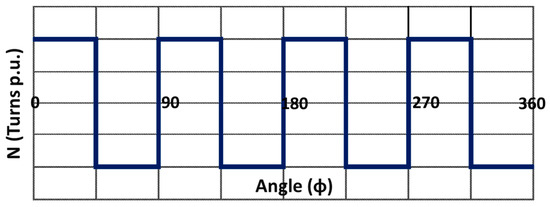
Figure 4.
Mode I winding function for phase A.
Equations (4)–(6) represent the Fourier series of odd harmonics of rectangular wave winding functions.
Using the expressions for currents and winding functions, the resultant magnetomotive force (MMF) for Mode I can be written as Equation (7):
As the resultant of three balanced sine waves becomes zero, therefore, the second term of Equation (7) becomes zero. Thus, the final form of MMF is given as Equation (8).
As shown in (8), the fundamental MMF component will be dominant, if the higher order harmonics are ignored. Therefore, in Mode I, the proposed machine operates as conventional WRSM.
2.2.2. Mode II: Constant Power Operation
Figure 3b illustrates Mode II of the suggested topology. The proposed topology functions in this mode as a BL-WRSM to accomplish constant power in the field-weakening area. Switches S1–S6 are activated, connecting the central point of the stator windings XYZ to tap into them. This results in winding XYZ having half the number of turns compared to winding ABC. The winding function for the winding configuration of Mode II is shown in Figure 5. In contrast, the closure of switch S7 establishes a parallel connection between the field winding and harmonic winding via a bridge rectifier. Meanwhile, switch S8 is opened to disconnect the field winding from both the slip-ring and brushes assembly as well as the external DC supply.
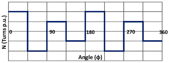
Figure 5.
Mode II winding function for phase A.
Because of the different winding turns of both stator windings, the winding functions for Mode II are given in Equations (9)–(11). Moreover, the resultant MMF by ignoring the higher order harmonics is represented in (12).
The second term of Equation (12) represents the sub-harmonic (SH) component of the airgap MMF. This SH component of stator MMF (SH-MMF) is generated along with the fundamental component of stator MMF. This extra SH-MMF produces the voltage across the harmonic winding, which is then rectified to feed the DC current, as required by the field winding of the machine. The schematic diagram of the rotor harmonic and field winding used in the circuit editor is shown in Figure 6. This special arrangement of stator winding makes the proposed DMDS-WRSM to operate, which is BL-WRSM. In Mode II of the proposed machine, a state of constant power is attained within the field-weakening region [21].
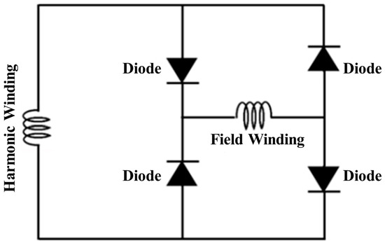
Figure 6.
Schematic diagram of rotor harmonic and field winding.
3. Design Consideration of Proposed Machine
3.1. Existing Single-Stator BL-WRSM
Figure 7a shows the machine structure of the existing single-stator BL-WRSM, which is an outer-stator topology. The stator of the machine consists of a double-layer distributed winding with 48 slots. The stator winding comprises two sets of windings connected in series, namely winding ABC and winding XYZ. There are two distinct windings: the field winding and the harmonic winding in the rotor. With the pole pitch of the field winding being half that of the harmonic winding, it leads to a configuration of four poles for the harmonic winding and eight poles for the field winding.
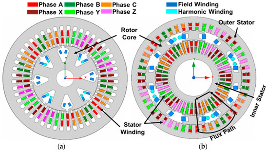
Figure 7.
Machine structure and winding configuration: (a) existing BL-WRSM; (b) proposed DMDS-WRSM.
3.2. Proposed Dual-Mode Dual-Stator BL-WRSM
3.2.1. Machine Layout
The proposed dual-mode dual-stator WRSM topology is validated by designing a machine with 8 poles and 48 slots. It has two stators, which are aligned with each other, and a sandwiched rotor. An 8-pole, double-layer distributed winding is configured on both stators. Both stators have two sets of three-phase windings, the winding AoBoCo/AiBiCi and winding XoYoZo/XiYiZi, and these windings are joined in series. The machine model and winding configuration are illustrated in Figure 7b. Two distinct windings, namely the field winding and harmonic winding, are positioned on the rotor. The harmonic winding is configured with four poles, whereas the field winding is designed with eight poles.
3.2.2. Design Consideration
Apart from selecting the pole-slot combination, similar to the existing model of BL-WRSM, the total electric and magnetic loading, machine volume, and stator and rotor current density were also considered in the design of the proposed DMDS-WRSM for a fair comparison. While designing the proposed machine, the electrical loading for each of the two stators remained half in comparison to the electrical loading of the existing single-stator BL-WRSM. However, the magnetic loading was kept the same because both the existing and proposed machines have a single rotor. The volume of the proposed machine and the current densities for both stators and the rotor were considered similar to the existing BL-WRSM. The slot depth of the inner stator was increased compared to that of the outer stator to maintain a similar slot-fill factor for both stators.
3.3. Analysis Conditions for Comparison
Table 1 lists the design constraints for the validation of the proposed machine’s contribution in comparison to the existing BL-WRSM. The analysis conditions for comparison were as follows:

Table 1.
Machine design parameters.
- (a)
- Both the existing and proposed machines had the same iron material.
- (b)
- For a fair comparison, the number of turns per coil of the stator and field winding were kept equal for both machines. The copper wire diameter was also selected to be the same for the stator and field-winding coil.
- (c)
- The stator current density for both the machines was 4.33 .
- (d)
- The machine volume was almost kept the same for a fair comparison of the current used BL-WRSM and the proposed DMDS-WRSM.
- (e)
- Airgap length was kept the same for both machines.
4. Performance Analysis by 2-D FEA
To validate the operational principle and compare the operational capabilities of the proposed machine with the existing BL-WRSM (brushless wound rotor synchronous machine), a 2D FEA has been conducted.
4.1. Flux Density Distribution Comparison
Figure 8 illustrates the comparison of the flux density distribution (B) of the existing and proposed DMDS-WRSM. The flux density of the existing BL-WRSM is presented in Figure 8a. The flux density in the segment of the machine with winding ABC is higher related to winding XYZ. This difference in the amount of flux density is a result of the winding ABC having twice the number of turns relative to the winding XYZ. Figure 8b depicts the distribution of the flux density in the proposed DMDS-WRSM operating in Mode I at its rated speed. Flux density is equally distributed in this mode because the proposed machine worked as a conventional WRSM in this mode of operation. Figure 8c displays the flux density distribution of the proposed DMDS-WRSM operating in Mode II at its rated speed. As the quantity of turns in winding ABC is maintained twice as compared to winding XYZ in both stators of the proposed machine, consequently, the flux density in the specific area of the proposed machine using winding ABC is elevated as associated to the portion having the winding XYZ. The maximum flux density in both modes of the proposed machine is about 1.96 T on one of the edges of each rotor pole.
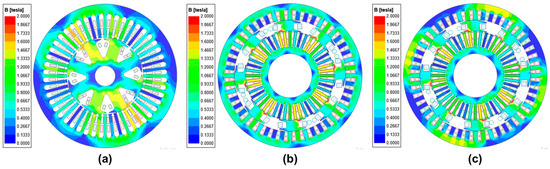
Figure 8.
Flux density distribution comparison at rated speed: (a) existing BL-WRSM; (b) Mode I of proposed DMDS-WRSM; (c) Mode II of proposed DMDS-WRSM.
The flux line distribution of the standing BL-WRSM and the proposed machine is compared in Figure 9. It was observed that the flux leakage in the existing BL-WRSM is higher compared to the proposed DMDS-WRSM, and as a result, the proposed machine demonstrates superior performance in comparison to the existing BL-WRSM.
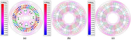
Figure 9.
Flux line distribution comparison at rated speed: (a) existing BL-WRSM; (b) Mode I of proposed DMDS-WRSM; (c) Mode II of proposed DMDS-WRSM.
4.2. Field-Current at Rated Speed
A current of 4.5 Arms at 60 Hz was supplied to the stator winding of both machines, and the rated speed was set to 900 rpm. A rated DC field current of 13.01 A was applied to activate the proposed DMDS-WRSM in Mode I, as depicted in Figure 10a. However, in the existing BL-WRSM and in Mode II of the proposed machine, the voltage induced in the harmonic winding by the SH-MMF is subsequently rectified to provide the field current to the field winding. The brushless operation of the proposed DMDS-WRSM, as depicted in Figure 10b,c, exhibits an induced field current of 9.9 A, which is lower than the 13.01 A observed in the standing BL-WRSM due to the increased flux leakage. The overall comparison of the field current in existing BL-WRSM and both modes of the proposed DMDS-WRSM at a steady state is illustrated in Figure 10d.
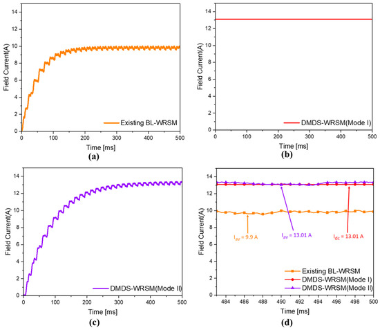
Figure 10.
Field current comparison at rated speed: (a) existing BL-WRSM; (b) Mode I of proposed DMDS-WRSM; (c) Mode II of proposed DMDS-WRSM; (d) overall comparison of field current.
4.3. Torque at the Rated Speed
At the rated speed, Figure 8 displays the torque characteristics of both the existing BL-WRSM and the proposed machine in Mode I and Mode II operation. The average torque of the existing BL-WRSM is 7.8 N.m., as depicted in Figure 11a. As depicted in Figure 11b, the proposed machine with its dual-stator structure shows an average torque of 8.5 N.m., which is 7.52% higher in comparison to the existing BL-WRSM. In Mode I, the proposed machine uses the full number of turns of both of the series-connected stator windings; therefore, the average torque in Mode I of the proposed machine is 11.3 N.m., as shown in Figure 11c. Figure 11d exhibits the overall comparison of the output torque at a steady state.
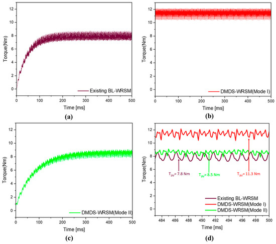
Figure 11.
Torque comparison at rated speed: (a) existing BL-WRSM; (b) Mode I of proposed DMDS-WRSM; (c) Mode II of proposed DMDS-WRSM; (d) overall comparison of field current.
4.4. Torque-Speed Characteristics of Existing BL-WRSM
Figure 12 shows the torque-speed characteristics of the existing BL-WRSM. The machine’s speed was adjusted to operate in the range from 800 rpm to 100 rpm within the constant torque region. With the decrease in speed, the voltage induced in harmonic winding decreased, leading to a subsequent reduction in the field current of the machine. As a result, the machine’s output torque also decreased. Hence, the existing BL-WRSM cannot achieve steady torque output at speeds below the rated value. However, in the field-weakening area, the RMS value of the stator current decreased from 4.5 A to 2.3 A. The reduction in the stator current led to a corresponding reduction in the induced field current, enabling the machine’s speed to increase.
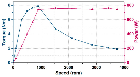
Figure 12.
Torque-speed characteristics of existing BL-WRSM.
4.5. Torque-Speed Characteristics of Proposed DMDS-WRSM
Figure 13 shows the torque-speed characteristics of the proposed DMDS-WRSM in the constant power and constant torque for the field-weakening region. In Mode I, the proposed machine is operated as a conventional WRSM. Therefore, due to the constant field current that acts as a constant cause of rotor flux, the proposed machine achieves a constant torque. In Mode II, the DMDS-WRSM is operated as BL-WRSM. The stator current is controlled to achieve a constant power in the field-weakening region.
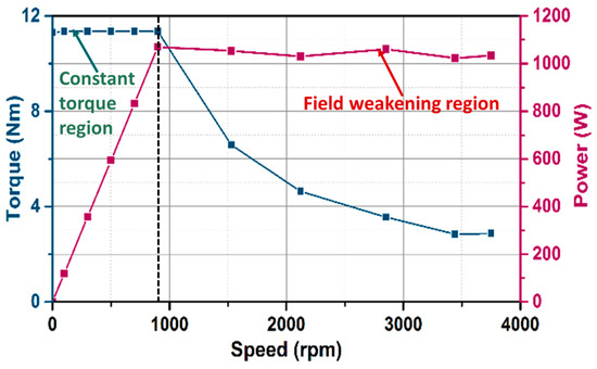
Figure 13.
Torque-speed characteristics of DMDS-WRSM.
4.6. Performance Comparison
Table 2 summarizes the performance comparison between the proposed DMDS-WRSM and the present BL-WRSM. Owing to the dual-mode operation, DMDS-WRSM achieved a constant torque in the constant region. During Mode I operation, the torque density of the proposed machine at the rated speed was 31.12% higher compared to that of the present BL-WRSM. The increased torque density in the proposed machine during Mode I operation can be attributed to the utilization of twice the quantity of turns in winding XYZ compared with the number of turns of winding XYZ in the existing BL-WRSM. Moreover, the torque density was 8.5% higher during the Mode II operational performance of the proposed machine because of its dual-stator structure. Moreover, the efficiency of the proposed machine is 3.4% higher in Mode I and 1.2% higher in Mode II compared to the existing BL-WRSM. The overall performance of the proposed DMDS-WRSM exhibits that because of the dual-mode and dual-rotor structure, the proposed machine performs better in terms of the starting torque, torque density, and output efficiency. Moreover, the wide speed range analysis of the proposed machine shows that this machine can be utilized for variable speed applications.
Table 2.
Performance comparison at rated speed.
5. Conclusions
This paper introduces a novel dual-mode dual-stator WRSM for variable speed applications, which overcomes the disadvantages of a low torque in a constant torque region in the case of single stator brushless WRSM. Because of the dual-mode operation, the proposed dual-mode topology makes the proposed machine suitable for applications that operate at varying speed. Moreover, due to the dual-stator structure, the proposed DMDS-WRSM exhibits an 8.5% higher torque compared to the currently used BL-WRSM. The performance of the proposed machine is analyzed using 2D FEA. The proposed DMDS-WRSM has higher torque density in both of its modes of operation, in comparison to the current BL-WRSM.
Author Contributions
Conceptualization, A.H.; methodology, A.H. and A.A.; software, A.H., A.A. and S.S.H.B.; validation, A.H., T.Y. and S.S.H.B.; formal analysis, A.H., S.S.H.B. and T.Y.; investigation, A.H.; resources, S.S.H.B.; writing—original draft preparation, A.H., A.A. and Z.B.; writing—review and editing, A.H., M.S. and A.A. All authors have read and agreed to the published version of the manuscript.
Funding
This research received no external funding.
Data Availability Statement
No new data were created or analyzed in this study. Data sharing is not applicable to this article.
Conflicts of Interest
The authors declare no conflict of interest.
References
- Soong, W.; Ertugrul, N. Field-weakening performance of interior permanent-magnet motors. IEEE Trans. Ind. Appl. 2002, 38, 1251–1258. [Google Scholar] [CrossRef]
- Bianchi, N.; Bolognani, S.; Chalmers, B. Salient-rotor PM synchronous motors for an extended flux-weakening operation range. IEEE Trans. Ind. Appl. 2000, 36, 1118–1125. [Google Scholar] [CrossRef]
- Burress, T.A.; Campbell, S.L. Evaluation of the 2010 Toyota Prius Hybrid Synergy Drive System; ORNL/TM-2010/253; Oak Ridge National Laboratory: Oak Ridge, TN, USA, 2011. [Google Scholar]
- Chau, K.T.; Chan, C.C.; Liu, C. Overview of Permanent-Magnet Brushless Drives for Electric and Hybrid Electric Vehicles. IEEE Trans. Ind. Electron. 2008, 55, 2246–2257. [Google Scholar] [CrossRef]
- Barcaro, M.; Bianchi, N. Interior PM Machines Using Ferrite to Replace Rare-Earth Surface PM Machines. IEEE Trans. Ind. Appl. 2014, 50, 979–985. [Google Scholar] [CrossRef]
- Lipo, T.A.; Du, Z.S. Synchronous motor drives—A forgotten option. In Proceedings of the 2015 Intl Aegean Conference on Electrical Machines & Power Electronics (ACEMP), 2015 Intl Conference on Optimization of Electrical & Electronic Equipment (OPTIM) & 2015 Intl Symposium on Advanced Electromechanical Motion Systems (ELECTROMOTION), Side, Turkey, 2–4 September 2015; pp. 1–5. [Google Scholar]
- Popescu, M.; Goss, J.; Staton, D.A.; Hawkins, D.; Chong, Y.C.; Boglietti, A. Electrical Vehicles—Practical Solutions for Power Traction Motor Systems. IEEE Trans. Ind. Appl. 2018, 54, 2751–2762. [Google Scholar] [CrossRef]
- Ali, Q.; Lipo, T.A.; Kwon, B.-I. Design and Analysis of a Novel Brushless Wound Rotor Synchronous Machine. IEEE Trans. Magn. 2015, 51, 8109804. [Google Scholar] [CrossRef]
- Ali, Q.; Atiq, S.; Lipo, T.A.; Kwon, B.I. PM assisted, brushless wound rotor synchronous machine. J. Magn. 2016, 21, 399–404. [Google Scholar] [CrossRef]
- Jawad, G.; Ali, Q.; Lipo, T.A.; Kwon, B.-I. Novel Brushless Wound Rotor Synchronous Machine With Zero-Sequence Third-Harmonic Field Excitation. IEEE Trans. Magn. 2016, 52, 8106104. [Google Scholar] [CrossRef]
- Bukhari, S.S.H.; Sirewal, G.J.; Chachar, F.A.; Ro, J.-S. Dual-Inverter-Controlled Brushless Operation of Wound Rotor Synchronous Machines Based on an Open-Winding Pattern. Energies 2020, 13, 2205. [Google Scholar] [CrossRef]
- Ayub, M.; Bukhari, S.S.H.; Jawad, G.; Kwon, B.-I. Brushless wound field synchronous machine with third-harmonic field excitation using a single inverter. Electr. Eng. 2019, 101, 165–173. [Google Scholar] [CrossRef]
- Yao, F.; An, Q.; Sun, L.; Lipo, T.A. Performance Investigation of a Brushless Synchronous Machine With Additional Harmonic Field Windings. IEEE Trans. Ind. Electron. 2016, 63, 6756–6766. [Google Scholar] [CrossRef]
- Yao, F.; An, Q.; Gao, X.; Sun, L.; Lipo, T.A. Principle of Operation and Performance of a Synchronous Machine Employing a New Harmonic Excitation Scheme. IEEE Trans. Ind. Appl. 2015, 51, 3890–3898. [Google Scholar] [CrossRef]
- Hussain, A.; Kwon, B.-I. A new brushless wound rotor synchronous machine using a special stator winding arrangement. Electr. Eng. 2017, 100, 1797–1804. [Google Scholar] [CrossRef]
- Ayub, M.; Hussain, A.; Jawad, G.; Kwon, B.-I. Brushless Operation of a Wound-Field Synchronous Machine Using a Novel Winding Scheme. IEEE Trans. Magn. 2019, 55, 8201104. [Google Scholar] [CrossRef]
- Hussain, A.; Atiq, S.; Kwon, B.-I. Optimal Design and Experimental Verification of Wound Rotor Synchronous Machine Using Subharmonic Excitation for Brushless Operation. Energies 2018, 11, 554. [Google Scholar] [CrossRef]
- Hussain, A.; Atiq, S.; Kwon, B.-I. Consequent-Pole Hybrid Brushless Wound-Rotor Synchronous Machine. IEEE Trans. Magn. 2018, 54, 8206205. [Google Scholar] [CrossRef]
- Hussain, A.; Baig, Z.; Toor, W.T.; Ali, U.; Idrees, M.; Al Shloul, T.; Ghadi, Y.Y.; Alkahtani, H.K. Wound Rotor Synchronous Motor as Promising Solution for Traction Applications. Electronics 2022, 11, 4116. [Google Scholar] [CrossRef]
- Ayub, M.; Atiq, S.; Ali, Q.; Hussain, A.; Kwon, B.-I. Dual-Mode Wound Rotor Synchronous Machine for Variable Speed Applications. IEEE Access 2020, 8, 115812–115822. [Google Scholar] [CrossRef]
- Han, P.; Cheng, M.; Jiang, Y.; Chen, Z. Torque/Power Density Optimization of a Dual-Stator Brushless Doubly-Fed Induction Generator for Wind Power Application. IEEE Trans. Ind. Electron. 2017, 64, 9864–9875. [Google Scholar] [CrossRef]


Disclaimer/Publisher’s Note: The statements, opinions and data contained in all publications are solely those of the individual author(s) and contributor(s) and not of MDPI and/or the editor(s). MDPI and/or the editor(s) disclaim responsibility for any injury to people or property resulting from any ideas, methods, instructions or products referred to in the content. |
© 2023 by the authors. Licensee MDPI, Basel, Switzerland. This article is an open access article distributed under the terms and conditions of the Creative Commons Attribution (CC BY) license (https://creativecommons.org/licenses/by/4.0/).