Article

Effects of Crosswind on Pantograph–Catenary Wear Using Nonlinear Multibody System Dynamic Algorithms

by
Siripong Daocharoenporn
1,* and
Mongkol Mongkolwongrojn
2,*
1
Department of Mechanical Engineering, Faculty of Engineering, King Mongkut’s Institute of Technology Ladkrabang, Bangkok 10520, Thailand
2
King Mongkut’s Institute of Technology Ladkrabang, College of Advanced Manufacturing Innovation, Bangkok 10520, Thailand
*
Authors to whom correspondence should be addressed.
World Electr. Veh. J. 2023, 14(9), 250; https://doi.org/10.3390/wevj14090250
Submission received: 7 August 2023 / Revised: 30 August 2023 / Accepted: 4 September 2023 / Published: 6 September 2023

Abstract

:
In this study, a multibody system (MBS) computational framework is developed to determine the exact location of the contact point and wear prediction resulting from the pantograph–catenary interaction. The railroad vehicle models in the MBS computational framework comprise rigid-body railroad vehicles, rigid-body pantograph systems, and flexible catenary systems. To avoid incremental rotation, the nonlinear finite element absolute nodal coordinate formulation is used to model a flexible catenary system in the MBS computational framework. To avoid co-simulation processes, the rigid-body railroad vehicle and the pantograph and flexible catenary systems were integrated into the MBS algorithms. The pantograph–catenary interaction is modeled using an elastic contact formulation developed to include the effect of pantograph–catenary separation and sliding contact. The proposed MBS approach evaluates the location of the contact point, contact force, and normal wear rate (NWR) from the mechanical and electrical contributions. This investigation considers the vibration caused by a crosswind scenario and determines the numerical result in the case of a steady crosswind scenario. The steady crosswind scenario contains the advantage of pantograph–catenary aerodynamic design, and the vibration of the catenary system remains significant after the excitation of a steady crosswind. In the case of a steady crosswind, the higher value of the steady crosswind effect significantly increases the mean contact force and the NWR from the mechanical contribution. After crosswind load disturbances, the mean contact force decreases, but the standard deviation of the contact force increases. Therefore, the NWR from the electrical contribution increases significantly. However, the total NWR increases with the crosswind velocity.

1. Introduction

This study uses detailed railroad vehicle models to develop a general multibody system (MBS) approach for pantograph–catenary wear prediction. This approach enables the localization of the pantograph–catenary contact point and wear prediction in different wind cases. The location of the pantograph–catenary contact point is identified by the developed elastic contact formulation, which considers the length and lateral displacement parameters of the flexible contact wire and rigid panhead, respectively. Here, the effects of a steady crosswind on lateral displacement are considered using the proposed MBS framework for wear prediction.
The dynamics of the pantograph–catenary system are crucial in today’s collection quality. Therefore, an accurate MBS computational framework should be used to estimate the contact force appropriately [1,2,3,4,5,6,7]. The MBS computational framework has been extensively developed to calculate the contact force generated by the pantograph–catenary interaction. The absolute nodal coordinate formulation (ANCF) theory has been developed and adopted in different research fields, such as fluid–structure interaction, road vehicles, tire modeling, and rail vehicles [8]. The ANCF has been used in engineering to predict the large deformation of flexible elements. In rail vehicles, the contact and messenger wires in the catenary system were modeled by the ANCF cable element. The ANCF cable element was applied to the multibody dynamic system (MBS) via a contact formulation to analyze the dynamic behavior of the pantograph–catenary system [1,2,5,9]. Several computational models that examine inclement weather and the effect of aerodynamic force on the pantograph–catenary interaction were developed earlier [10,11,12,13,14,15]. The vibration conditions or irregular profile of the pantograph–catenary system is part of the reason why operational problems supply the desired electric power supply [15,16,17]. The dynamic behavior was calculated using the equation of motion between the catenary and pantograph models based on the finite element (FE) method. Dynamic behavior analysis of contact wire irregularities, such as geometric distortion, periodic short wavelengths, and local imperfections caused by wire kinks, can be applied to detect wire irregularities in actual operations [18]. The dynamic behavior of railroad vehicles, including the translation and rotation effect of bogie and wheel–rail interaction, inevitably disturbs the pantograph–catenary interaction and may reduce the reliability of the pantograph–catenary system under the extreme conditions of an irregular track [19]. The accelerated wear rate on the pantograph–catenary interaction potentially damages system hardware, resulting in unsafe transportation system operation and expensive maintenance costs [20,21,22,23]. The mean contact force and wear rate were essential concerns in this investigation. The standards EN 50318 [24] 24 specify the technical criteria for the dynamics of the current collection systems of railroad vehicles. The acceptable value of mean contact force is specified by velocity in kilometer per hour as F m = 0.00097 v 2 + 70 N . The acceptable value of standard deviation is less than three tenths of the value of the mean contact force. The acceptable value of percentage of real arcing is less than 0.2 percent. These standards are referenced to validate the computational model and ensure that these model data and parameters are consistent with the specified standard operational guidelines.
The primary purpose of this study is to develop an MBS computational framework to determine the exact location of the contact point and wear prediction considering the pantograph–catenary interaction. Such a framework details the rigid-body railroad vehicle, pantograph system, and ANCF catenary system. Using the incremental rotation and co-simulation processes is unnecessary because the ANCF elements integrate the rigid-body railroad vehicle and the pantograph and flexible catenary systems into the MBS algorithms. The contact forces between the pantograph and catenary are modeled using a developed elastic contact formulation to include the effect of the pantograph–catenary separation and sliding contact. This study clarifies the Bucca and Collina [20] wear model of the tribological parameter developed from pantograph–catenary system operation. The wear mechanism is the impact of the complex interaction between mechanical and electrical effects. The wear from mechanical and electrical contributions is caused by the sliding friction and the high-intensity current flow. The wear from electrical arcs is caused by pantograph–catenary separation. The proposed MBS approach is used to evaluate the location of the contact point, contact force, and normal wear rate (NWR) from the mechanical and electrical contributions. This investigation particularly examines the vibration caused by the wind scenario. The steady wind scenario, which has a pantograph–catenary design feature, evaluates the contact force result and the NWR of the contact wire using the wear model. The effect of the contact wire vibration remains after the steady wind effect on the pantograph–catenary contact force and NWR of the contact wire are evaluated. Figure 1 shows the schematic diagram of the simulation model.

2. Wear Model

Bucca and Collina [20] created a wear formulation which was adopted to investigate the wear characteristics of the copper contact wire. The tribological parameters are generated by the complex interaction of the mechanical and electrical factors. The wear mechanism is represented by the mechanical contribution from sliding friction, the Joule effect from high-intensity current flow, and the result of electrical arcs from the pantograph–catenary separation. Bucca and Collina [20] developed a test rig to collect data on which the parameters can be adjusted to construct an inclusive wear model, as shown in Figure 1. The contact strip and contact wire in all tests were Kasperovski and pure copper, respectively. The NWR of the copper contact line, which is the wear volume per unit distance (mm3/km), is a feature of the principal operating parameters and a constant value resulting from the following experiment:
N W R = 1 4548.3 1 + I c 500 4.5 F m 2.8 + 1 68 R c F m I c 2 V 1 u + u I c 91,635 V  
Table 1 presents definitions of all parameters in this study. The electrical contact resistance R c is a function of the contact force F m , which can be expressed as follows [21]:
R c F m = 0.013 + 0.09   ·   e F m 14 / 11
Interdependent mechanical and electrical components contribute to the complex wear mechanism of the catenary contact wire. The contact force results from the MBS simulation of the detailed rail vehicle system in each scenario are postprocessed using this wear model. The wear model is modeled and integrated into the MBS computer program Sigma/Sams (systematic integration of geometric modeling and analysis for the simulation of articulated mechanical systems).

3. Pantograph–Catenary Contact Force Formulation

This section studies the developed elastic contact formulation. A contact formulation suitable for ANCF catenary systems has been developed from a sliding constraint and an elastic contact formulation [1,2]. The assumption that comes with the sliding joint contact formulation is no pantograph–catenary separation [1,3,4]. The developed elastic contact formulation allows for pantograph–catenary separation, and the effect of friction on the sliding motion can be applied [5]. Two relative degrees of freedom of the translational motion between the contacting bodies are eliminated using the developed elastic contact mathematical formulation. The contact point slides in the longitudinal direction along the contact wire and the lateral direction along the panhead. The developed elastic contact force formulation is applied, and the developed elastic contact mathematical formulation is explained.

3.1. Contact Point and Contact Frame

The location of the contact point on the pantograph–catenary system in the case of a zigzag catenary pattern and curved track should be considered, as well as the effect of the catenary system vibration. There is lateral displacement on the panhead, and superelevation on the curved track causes vertical displacement of the contact point or its location. Therefore, the developed elastic contact formulation is used to determine the exact location of the contact point as follows:
C s = r c p T r x c r c p T n 1 c r c p T n 2 c = C e 1 s C e 2 s C m s
where r c = S c x , y , z e c t is the absolute position vector of the catenary at the contact point defined as ANCF FE; S c is the matrix of the ANCF cable element shape function; x , y , and z are spatial coordinates of the element; r p is the panhead’s position vector at the contact point defined as r p = R p + A p u ¯ p assuming that R p is the position vector of the panhead’s middle point; u ¯ p = [ 0 y ¯ 0 ] T , where y ¯ is the panhead’s lateral displacement; A is the transformation matrix denoted as A = a 1 a 2 a 3 ; and r c p is a different panhead and catenary position vector denoted as r c p = r c r p . Three orthogonal vectors [6,7] are denoted as
r x c = r x c 1 r x c 2 r x c 3 , n 1 c = r x c 1 r x c 2 r x c 1 2 + r x c 3 2 r x c 2 r x c 3 , n 2 c = r x c 3 0 r x c 1
The contact frame is defined using a single vector r x c . This frame formulation faces the singularity problem if the vector r x c parallels the vector 0 1 0 T . Three vectors are used to define the contact frame r x c = 0 r x c 2 0 T ,   n 1 c = r x c 2 0 0 T , and n 2 c = 0 0 1 T .
An algebraic equation is developed to solve two sliding directions on the panhead via the geometric parameter. This geometric parameter is the contact point location on the flexible contact wire and the rigid panhead using the elastic contact formulation with two parameters: the flexible contact wire’s length parameter ( s 1 ) and the rigid panhead’s lateral displacement parameter ( s 2 ). Assuming x = x s 1 and y ¯ = s 2 , the elastic contact formulation is as follows:
C e s = C e 1 s C e 2 s
For the simulation time step under consideration, the generalized variables for the panhead and contact wire from the numerical integration can solve the algebraic equation C e s = 0 to obtain the flexible contact wire’s length parameter ( s 1 ) and the rigid panhead’s lateral displacement parameter ( s 2 ). Using the equation for the iterative Newton–Raphson algorithm as
C e s s Δ s = C e s
where s = s 1 s 2 T and C e s s = [ C e 1 s / s C e 2 s / s ] T , assume that the term of C e s s is always nonzero. The Newton difference can be calculated as
Δ s 1 Δ s 2 = J 1 C e s
where the Jacobian terms are J = C e s s = [ C e 1 s / s C e 2 s / s ] T = r c p T r x x c + r x c T r x c a 2 p T r x c r c p T H 1 r x x c + r x c n 1 c a 2 p T n 1 c and H 1 = n 1 c r s 1 c = r x c 2 r x c 1 0 2 r x c 1 0 2 r x c 3 0 r x c 3 r x c 2 .

3.2. Contact Forces

A penalty force hypothesis based on the elastic contact force formulation, which allows pantograph–catenary separation, is used to calculate the generalized contact and friction forces on the pantograph–catenary interaction. The variables in each of the two orthogonal directions are defined as l 2 = a 2 c T r c p and l 3 = a 3 c T r c p . A penalty force model F 3 c p l 3 ,   l ˙ 3 ,   k 3 c p ,   c 3 c p is defined along the aforementioned orthogonal directions a 3 c , where k k c p and c k c p are the user-defined stiffness and damping coefficients, respectively. The friction force is calculated as F t c p = μ F 3 c p a 1 c + a 2 c / a 1 c + a 2 c , where μ is the friction coefficient. The friction force along the aforementioned orthogonal directions a 1 c and a 2 c is F k c p l k , l ˙ k = μ F 3 c p a k c / a 1 c + a 2 c ,   k = 1 ,   2 . The virtual work principle can generate generalized forces associated with the pantograph–catenary interaction generalized coordinates, which can be expressed as
Q p = k = 1 3 F k c p l k , l ˙ k l k q p T , Q c = k = 1 3 F k c p l k , l ˙ k l k q c T
In the previous set of algebraic equations, the parameters’ superscripts c and p refer to the catenary and pantograph at the contact point, respectively.

4. Pantograph–Catenary Aerodynamic Force Formulation

The aerodynamic force formula used here is ideal for rigid pantograph and ANCF catenary systems to model the effect of aerodynamic forces. The aerodynamic forces can be expressed as
F D = 1 2 ρ C D A v r 2 v ^ D ,   F L = 1 2 ρ C L A v r 2 v ^ L
The drag and lift force coefficients are determined from earlier experiments [10,11,12]. The generalized aerodynamic forces associated with the generalized coordinates at point i can be expressed as
Q D = i = 1 N J i T F D i and   Q L = i = 1 N J i T F L i
where N is the number of points.

5. The ANCF Catenary System Model

The catenary design is critical to the stable operation of the current collection system of an electric locomotive. The vibration of the catenary caused by pantograph–catenary interaction and the influence of the environmental wind are vital for its smooth operation. The catenary system mainly comprises a contact wire, messenger wire, and dropper. Figure 2 shows the structure of the computational catenary model. The droppers that connect the messenger and contact lines are stiff when tensioned and not stiff when compressed. In the numerical model, the initial length of the droppers and the tension on the catenary system prevent catenary sagging. A tension force is implemented in the catenary system to control the catenary wave propagation speed, which is critical for maintaining its consistent contact with the panhead [25,26]. The pretension force of the catenary wire is calculated to determine the appropriate nodal coordinates of the ANCF cable elements. The design catenary parameter used in this study was previously mentioned in [5]. Figure 3 shows the schematic of a catenary system.
In this study, the ANCF FE formulation is completely non-incremental. ANCF enables the modeling of a flexible catenary system, nonlinear pantograph mechanism, and detailed rail vehicle model in a single multibody framework without using co-simulation techniques [27]. Because of the absence of some complex coupled deformation modes, the ANCF cable elements can represent geometric nonlinearities and do not experience locking issues like other completely parameterized ANCF beams and plates [28]. The cable elements are excellent for the current problem statement because they can represent extension and bending in thin rods. As a gradient-deficient element, the limitation of the ANCF cable element is its inability to assess the rotation of its axis, which is insignificant in the context of this investigation. The global position of the element is detailed as a function of the element’s spatial coordinates x = x y z T by the element kinematics as r x , t = S x e t , where the shape function is a function of the element’s spatial coordinates, and the element’s nodal coordinates are a function of time. For the ANCF cable element, the vector nodal coordinates for node k are e k = r k T r x k T T , k = 1 ,   2 . The shape function matrix is S = s 1 I   s 2 I   s 3 I   s 4 I   , where s 1 = 1 2 3 4 ξ + ξ 3 4 , s 2 = L 8 1 ξ ξ 2 + ξ 3 , s 3 = 1 2 + 3 4 ξ ξ 3 4 , s 4 = L 8 1 ξ + ξ 2 + ξ 3 , L is the element’s length, and ξ = 2 x / L 1 . This ANCF cable element yields a constant mass matrix, defined as M e = 0 L ρ e A e S T S d x . The virtual work of the elastic forces can be written as δ W e = 0 L E I e κ δ κ + E A e ε x x δ ε x x d x , where the first term represents the bending strain energy and the second depicts the axial strain energy. ANCF cable elements can accurately capture large deformations and ensure the continuity of slopes and rotations at nodal points.

6. MBS Model and Equations of Motion

This section details the MBS and wheel–rail contact models, elaborating on the equations of motion. The rigid and flexible MBS model is modeled and solved using the MBS computer program Sigma/Sams.

6.1. Railroad Vehicle and Pantograph MBS Models

This MBS model can be integrated into the rail vehicle dynamics behavior and pantograph–catenary interaction, which is validated in [5]. Figure 4 shows the rail vehicle components as constructed in Sigma/Sams. The pantograph MBS model uses the Faiveley Transport CX pantograph with a single contact strip [1,2,5,29]. Figure 5 presents the MBS model schematic of the pantograph–catenary system.

6.2. Wheel–Rail Contact Kinematics

The wheel–rail contact model is critical for understanding the behavior of rail vehicle dynamics. Wheel–rail contact simulation uses a three-dimensional (3D) nonconformal contact model [30]. The contact formulation allows for wheel–rail separation and the incorporation of a general description of the wheel–rail profile geometries. The following nonlinear algebraic equations are used in conjunction with the concept of nongeneralized coordinates:
C w , r q r , q w , s r , s w , t = t 1 r T r w r r t 2 r T r w r r t 1 w T n r t 2 w T n r = 0
In the previous set of algebraic equations, the parameters’ superscripts w and r refer to the wheel and rail, respectively. The equation of the iterative Newton–Raphson algorithm can be used to solve the nonlinear equations as
C w , r / s w Δ s w + C w , r / s r Δ s r = C w , r
where Δ s w and Δ s r are the Newton differences. The solution includes four surface parameters corresponding to each wheel and rail, used to specify the location of the rail–wheel contact point. The locations of rail–wheel contact points must be the same along the two tangent vectors corresponding to the rail geometry. The contact force model can specify generalized forces on the wheels and rails, comprising normal forces, creepage forces, tangential creep forces, and spin moment.

6.3. MBS Equations of Motion

The MBS equations of motion are used to solve the position, velocity, and acceleration vector for the rigid and flexible bodies in the model. The differential-algebraic equations are solved using a two-loop sparse matrix numerical integration procedure [31]. The MBS equations of motion in the augmented Lagrangian form can be expressed as
M r r 0 0 C q r T 0 M e e 0 C e T 0 0 0 C s T C q r C e C s 0 q ¨ r e ¨ s ¨ λ = Q r Q e 0 Q c
In the previous set of algebraic equations, the parameters’ subscripts r , e , and s refer to the coordinates associated with the reference, ANCF coordinates, and nongeneralized coordinates, respectively.

7. Numerical Results and Discussion

The rail vehicle is assumed to operate at a forward velocity of 80 km/h with fundamental torque from the traction motor on the tangent track. An uplift force of 1650.69 N is applied to the pantograph mechanism. The numerical results in Figure 6 verify that the model’s parameters are suitable for the EN 50318 standards. In the case of the dynamic behavior analysis, due to the steady crosswind effect on the tangent track, the steady crosswind direction is horizontal and perpendicular to the tangent track. Figure 7 displays the contact force history over time as the rail vehicle moves through the steady crosswind. The contact force of each case is analyzed in the mean contact force and standard deviation (SD) of the contact force, as concluded in Table 2. The mean contact force, SD of the contact force, mean NWR from mechanical (MNWR) and electrical contributions (ENWR), total mean NWR (TNWR), and percentage of contact loss are analyzed in Table 2 to examine the wear behavior of the pantograph–catenary system. The steady crosswind direction is horizontal and perpendicular to the tangent track. Numerical results show that the mean contact force increases with an increase in the steady crosswind velocity because of the aerodynamic lift force on the pantograph–catenary system, which reduces the percentage of contact loss, and the mean NWR from the mechanical contribution also increases. With the increase in the steady crosswind, the trend of the mean NWR from the mechanical and electrical contributions is similar to that of the mean contact force and SD of the contact force, respectively. The increase in the SD is not related to the percentage of contact loss because of the increase in the mean contact force. These results indicate an advantage of pantograph–catenary aerodynamic design, in which the steady crosswind causes a lift force on the pantograph and a downforce on the catenary. Interestingly, the total NWR slightly decreases because the decreasing value of the mean NWR from the electrical contribution is more than the increasing value of the mean NWR from the mechanical contribution. To increase the NWR effect from the mechanical contribution, the uplift force on the pantograph mechanism in the simulation increases from 1650.69 to 1815.69 N. The mean NWR is shown in Table 3. The trends of the mean contact force, SD of the contact force, and mean NWR from the mechanical and electrical contributions with the increase in steady crosswind velocity and uplift force are the same. However, the mean total NWR increases because the decreasing value of the mean NWR from the electrical contribution is less than the increasing value of the mean NWR from the mechanical contribution. Therefore, the numerical results, which follow the EN 50318 standards and the aerodynamic design of the pantograph–catenary system, show the advantage for wear behavior on the catenary when the vehicle moves through 10 m/s of steady crosswind, and the mean of the total NWR is approximately the same.
In the case of the dynamic behavior analysis caused by the vibration on the catenary system after crosswind disturbances, to analyze the vibration effect on both wires, we assume that the total duration of the steady crosswind is the first 2.5 s, and the steady crosswind direction is horizontal and perpendicular to the tangent track. The rail vehicle is set to move at a forward velocity of 80 km/h with fundamental torque of the traction motor and 1650.69 N of uplift force on the pantograph mechanism. Figure 8 shows the time history of the contact force. There is contact loss on the first span because the vibration effect of the contact wire continues, and the SD of the contact force slightly decreases in each span. Table 4 summarizes the results of the mean contact force, SD of the contact force, mean NWR from MNWR and ENWR, TNWR, and percentage of contact loss. The mean contact forces in all cases are almost the same, whereas the SD of the contact force increases because the vibration of the contact wire continues without the advantage of the pantograph–catenary aerodynamic design. The mean NWR from the mechanical and electrical contributions is related to the value of the mean contact force and SD of the contact force, respectively. The mean total NWR increases with the increase in the mean NWR value from the mechanical and electrical contributions. With the increase in the crosswind velocity, the contact force fluctuation and the percentage of contact loss also increase.

8. Conclusions

This study proposes a general MBS approach for predicting wear in the contact wire caused by the dynamic pantograph–catenary interaction. Well-developed analytical and empirical wear formulas from extensive experiments and field tests are proposed for 3D railroad vehicle models. The catenary contact and messenger wires are modeled using the ANCF gradient-deficient cable elements. The nonlinear dynamic interaction between the rigid panhead and flexible catenary is described using an elastic contact force model. The integration of the MBS computational framework and wear model was previously validated [5].
Dynamic behavior analysis of the effect of steady crosswind based on the tangent track is performed based on the EN 50318 standards. The rail vehicle was moving forward at 80 km/h with fundamental torque from the traction motor on the tangent track and the horizontal steady crosswind perpendicular to the tangent track. The wear characteristics of the pantograph–catenary system under crosswind disturbances have been examined and can be concluded as follows:
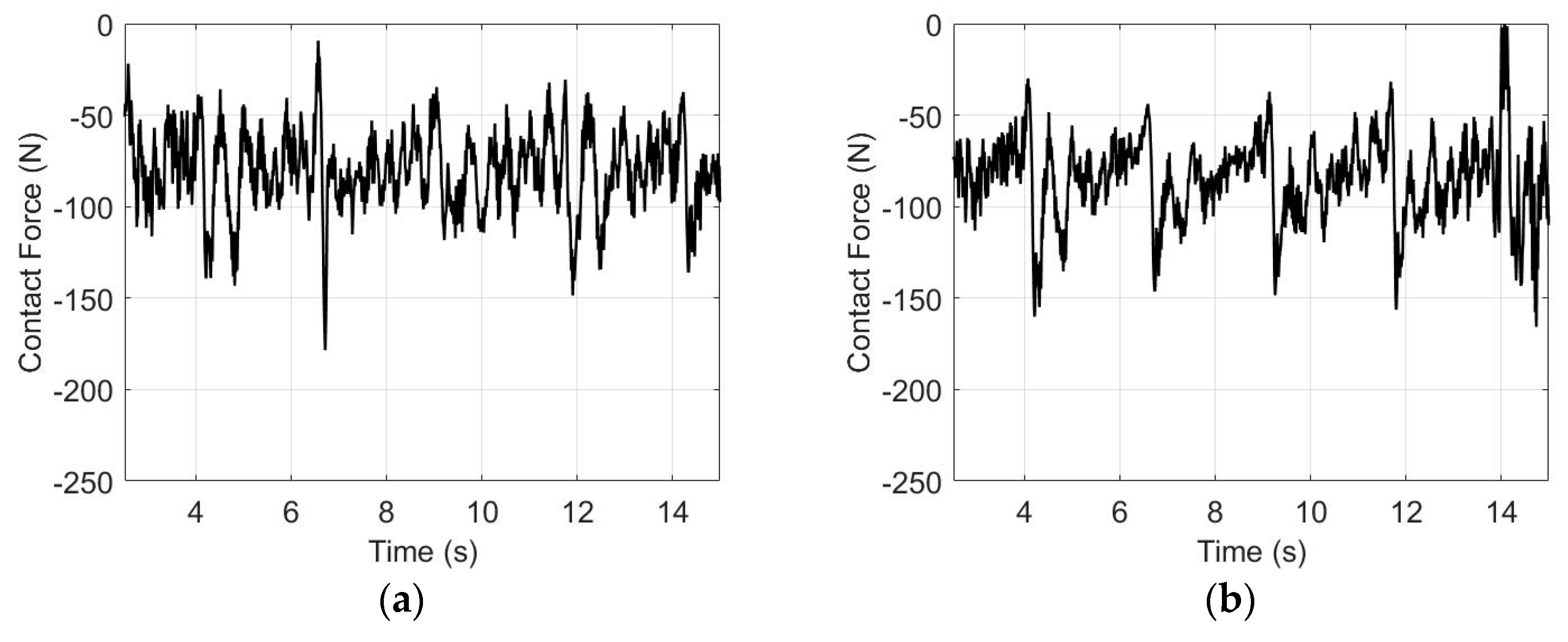
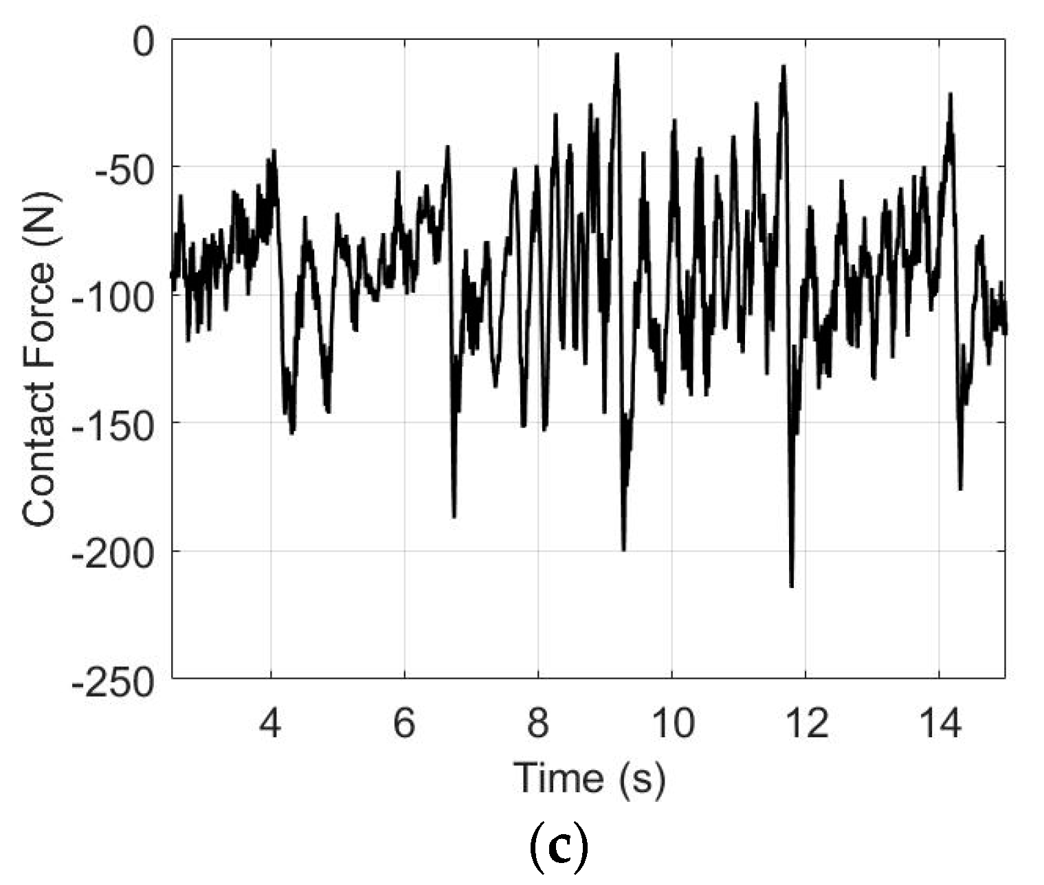
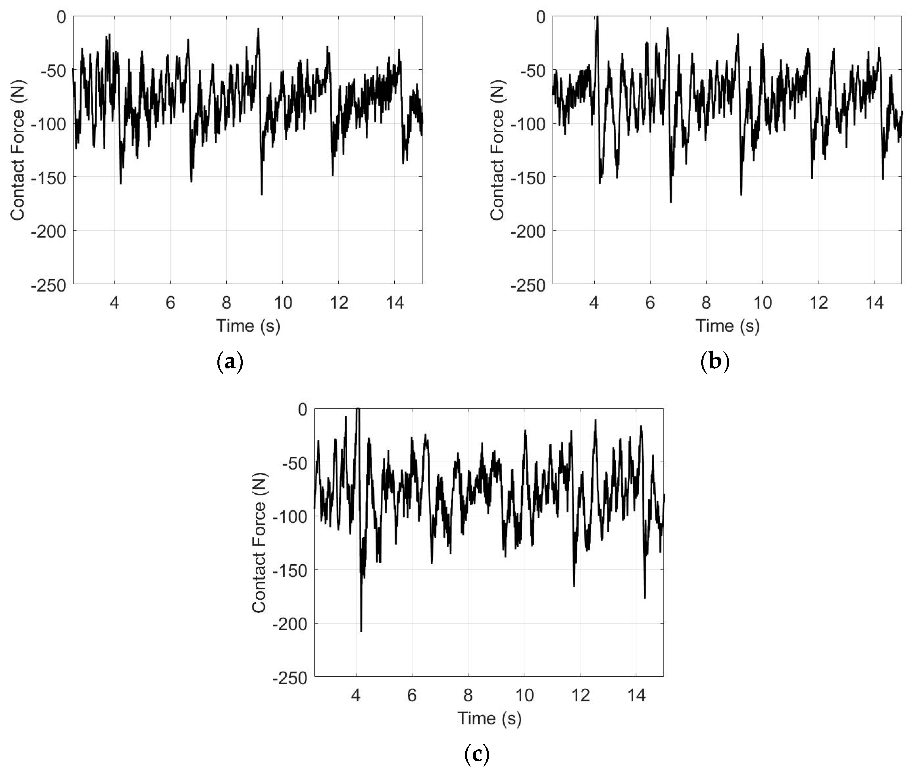
  • The total NWR caused by the contact wire vibration during the crosswind excitation: for the pantograph and catenary with the aerodynamic design, the steady crosswind load increases the NWR of the contact wire from the mechanical contribution because of the increase in the contact force between the pantograph and catenary. The contact force fluctuation increases with the increase in the crosswind velocity. The NWR of the contact wire from the electrical contribution increases nonlinearly. Therefore, the total NWR is insignificant for the low-velocity crosswind and increases significantly for the high-velocity crosswind.
  • The total NWR caused by the contact wire vibration after the crosswind excitation: the results show an increase in the SD of the contact force. The NWR from the electrical contribution and the percentage of contact loss increase significantly, whereas the mean contact force and NWR of the mechanical contribution remain almost unchanged. The total NWR increases significantly for the high-velocity crosswind.
  • After the excitation of the high-velocity crosswind, a significant dispersion of the pantograph–catenary interaction and contact loss of the pantograph–catenary can occur because of severe vibration. The large uplift force in the pantograph head is necessary to suppress vibration. Therefore, a higher mean contact force causes higher wear, whereas a low mean contact force can reduce the reliability of the pantograph–catenary system.

Author Contributions

All authors contributed to the study conception and design. Material preparation, data collection, and analysis were performed by S.D. under M.M.’s supervision. The first draft of the manuscript was written by S.D., S.D. and M.M. commented on previous versions of the manuscript. S.D. referred to the Authorship Principles when he developed the multibody system (MBS) computational framework for this research work. All authors have read and agreed to the published version of the manuscript.

Funding

This work was supported by the Thailand Research Fund through the Royal Golden Jubilee Ph.D. Program (Grant number Ph.D./0154/2557).

Data Availability Statement

The datasets generated during and/or analyzed during the current study are not publicly available because the data supporting the results in our research work were obtained from our calculations but are available from the corresponding author on reasonable request.

Acknowledgments

Amed A. Shabana and Shubhankar Kulkarni are acknowledged for contributing to the computational resources.

Conflicts of Interest

We confirm that none of the authors of the manuscript have financial interest or conflict of interest to declare.

References

  1. Pappalardo, C.M.; Patel, M.D.; Tinsley, B.; Shabana, A.A. Contact force control in multibody pantograph/catenary systems. Proc. Inst. Mech. Eng. Part K J. Multi Body Dyn. 2016, 230, 307–328. [Google Scholar] [CrossRef]
  2. Kulkarni, S.; Pappalardo, C.M.; Shabana, A.A. Pantograph/catenary contact formulations. J. Vib. Acoust. 2017, 139, 011010. [Google Scholar] [CrossRef]
  3. Seo, J.H.; Sugiyama, H.; Shabana, A.A. Three-dimensional large deformation analysis of the multibody pantograph/catenary systems. Nonlinear Dyn. 2005, 42, 199–215. [Google Scholar] [CrossRef]
  4. Seo, J.H.; Kim, S.W.; Jung, I.H.; Park, T.W.; Mok, J.Y.; Kim, Y.G.; Chai, J.B. Dynamic analysis of a pantograph–catenary system using absolute nodal coordinates. Veh. Syst. Dyn. 2006, 44, 615–630. [Google Scholar] [CrossRef]
  5. Daocharoenporn, S.; Mongkolwongrojn, M.; Kulkarni, S.; Shabana, A.A. Prediction of the pantograph/catenary wear using nonlinear multibody system dynamic algorithms. J. Tribol. 2019, 141, 051603. [Google Scholar] [CrossRef]
  6. Gere, J.M.; Weaver, W. Analysis of Framed Structures; Van Nostrand: New York, NY, USA, 1965. [Google Scholar]
  7. Shabana, A.A. Dynamics of Multibody Systems, 4th ed.; Cambridge University Press: Cambridge, UK, 2013. [Google Scholar]
  8. Otsuka, K.; Makihara, K.; Sugiyama, H. Recent advances in the absolute nodal coordinate Formulation: Literature review from 2012 to 2020. J. Comput. Nonlinear Dyn. 2022, 17, 080803. [Google Scholar] [CrossRef]
  9. Peng, C.; Yang, C.; Xue, J.; Gong, Y.; Zhang, W. An adaptive variable-length cable element method for form-finding analysis of railway catenaries in an absolute nodal coordinate formulation. Eur. J. Mech. 2022, 93, 104545. [Google Scholar] [CrossRef]
  10. Bocciolone, M.; Resta, F.; Rocchi, D.; Tosi, A.; Collina, A. Pantograph aerodynamic effects on the pantograph–catenary interaction. Veh. Syst. Dyn. 2006, 44 (Suppl. S1), 560–570. [Google Scholar] [CrossRef]
  11. Carnevale, M.; Facchinetti, A.; Maggiori, L.; Rocchi, D. Computational fluid dynamics as a means of assessing the influence of aerodynamic forces on the mean contact force acting on a pantograph. Proc. Inst. Mech. Eng. Part F J. Rail Rapid Transit 2016, 230, 1698–1713. [Google Scholar] [CrossRef]
  12. Song, Y.; Liu, Z.; Wang, H.; Lu, X.; Zhang, J. Nonlinear analysis of wind-induced vibration of high-speed railway catenary and its influence on pantograph–catenary interaction. Veh. Syst. Dyn. 2016, 54, 723–747. [Google Scholar] [CrossRef]
  13. Yao, Y.; Zou, D.; Zhou, N.; Mei, G.; Wang, J.; Zhang, W. A study on the mechanism of vehicle body vibration affecting the dynamic interaction in the pantograph–catenary system. Veh. Syst. Dyn. 2021, 59, 1335–1354. [Google Scholar] [CrossRef]
  14. Dai, Z.; Li, T.; Zhou, N.; Zhang, J.; Zhang, W. Numerical simulation and optimization of aerodynamic uplift force of a high-speed pantograph. Railw. Eng. Sci. 2021, 30, 117–128. [Google Scholar] [CrossRef]
  15. Song, Y.; Liu, Z.; Duan, F.; Lu, X.; Wang, H. Study on wind-induced vibration behaviour of railway catenary in spatial stochastic wind field based on nonlinear finite element procedure. J. Vib. Acoust. 2018, 140, 011010. [Google Scholar] [CrossRef]
  16. Shi, H.; Chen, G.; Yang, Y. A comparative study on pantograph-catenary models and effect of parameters on pantograph-catenary dynamics under crosswind. J. Wind. Eng. Ind. Aerodyn. 2021, 211, 104587. [Google Scholar] [CrossRef]
  17. Song, Y.; Jiang, T.; Nåvik, P.; Rønnquist, A. Geometry deviation effects of railway catenaries on pantograph–catenary interaction: A case study in Norwegian railway system. Railw. Eng. Sci. 2021, 29, 350–361. [Google Scholar] [CrossRef]
  18. Song, Y.; Rønnquist, A.; Jiang, T.; Nåvik, P. Identification of short-wavelength contact wire irregularities in electrified railway pantograph–catenary system. Mech. Mach. Theory 2021, 162, 104338. [Google Scholar] [CrossRef]
  19. Song, Y.; Wang, Z.; Liu, Z.; Wang, R. A spatial coupling model to study dynamic performance of pantograph-catenary with vehicle-track excitation. Mech. Syst. Signal Process. 2021, 151, 107336. [Google Scholar] [CrossRef]
  20. Bucca, G.; Collina, A. Electromechanical interaction between carbon-based pantograph strip and copper contact wire: A heuristic wear model. Tribol. Int. 2015, 92, 47–56. [Google Scholar] [CrossRef]
  21. Bucca, G.; Collina, A.; Manigrasso, R.; Mapelli, F.; Tarsitano, D. Analysis of electrical interferences related to the current collection quality in pantograph–catenary interaction. Proc. Inst. Mech. Eng. Part F J. Rail Rapid Transit 2011, 225, 483–500. [Google Scholar] [CrossRef]
  22. Bucca, G.; Collina, A. A procedure for the wear prediction of collector strip and contact wire in pantograph–catenary system. Wear 2009, 266, 46–59. [Google Scholar] [CrossRef]
  23. Zhang, Y.; Li, C.; Pang, X.; Song, C.; Ni, F.; Zhang, Y. Evolution processes of the tribological properties in pantograph/catenary system affected by dynamic contact force during current-carrying sliding. Wear 2021, 477, 203809. [Google Scholar] [CrossRef]
  24. EN 50318; Railway Applications—Current Collection Systems—Validation of Simulation of the Dynamic Interaction between Pantograph and Overhead Contact Line. European Standards (EN): Brussels, Belgium, 2002.
  25. Huan, R.H.; Pan, G.F.; Zhu, W.Q. Dynamics of pantograph-catenary system considering local singularities of contact wire with critical wavelengths. In Proceedings of the 1st International Workshop on High-Speed and Intercity Railways, Shenzhen and Hong Kong SAR, China, 19–22 July 2011; Lecture Notes in Electrical Engineering. Springer: Berlin/Heidelberg, Germany, 2012; pp. 319–333. [Google Scholar] [CrossRef]
  26. Tur, M.; García, E.; Baeza, L.; Fuenmayor, F.J. A 3D absolute nodal coordinate finite element model to compute the initial configuration of a railway catenary. Eng. Struct. 2014, 71, 234–243. [Google Scholar] [CrossRef]
  27. Bruni, S.; Ambrosio, J.; Carnicero, A.; Cho, Y.H.; Finner, L.; Ikeda, M.; Kwon, S.Y.; Massat, J.P.; Stichel, S.; Tur, M.; et al. The results of the pantograph–catenary interaction benchmark. Veh. Syst. Dyn. 2015, 53, 412–435. [Google Scholar] [CrossRef]
  28. Gerstmayr, J.; Shabana, A.A. Analysis of thin beams and cables using the absolute nodal co-ordinate formulation. Nonlinear Dyn. 2006, 45, 109–130. [Google Scholar] [CrossRef]
  29. Pombo, J.; Ambrósio, J.; Pereira, M.; Rauter, F.; Collina, A.; Facchinetti, A. Influence of the aerodynamic forces on the pantograph–catenary system for high-speed trains. Veh. Syst. Dyn. 2009, 47, 1327–1347. [Google Scholar] [CrossRef]
  30. Shabana, A.A.; Zaazaa, K.E.; Sugiyama, H. Railroad Vehicle Dynamics: A Computational Approach; CRC Press: Boca Raton, FL, USA, 2007. [Google Scholar]
  31. Aboubakr, A.K.; Shabana, A.A. Efficient and robust implementation of the TLISMNI method. J. Sound Vib. 2015, 353, 220–242. [Google Scholar] [CrossRef]
Figure 1. Schematic diagram of simulation model.
Wevj 14 00250 g001
Figure 2. Catenary computational model.
Wevj 14 00250 g002
Figure 3. Catenary system schematic.
Wevj 14 00250 g003
Figure 4. Rail vehicle system schematic.
Wevj 14 00250 g004
Figure 5. Pantograph–catenary model schematic.
Wevj 14 00250 g005
Figure 6. Contact force without the wind effect on the tangent track.
Wevj 14 00250 g006
Figure 7. Contact force with the steady crosswind effect on the tangent track: (a) 10, (b) 20, and (c) 30 m/s of steady wind velocities.
Wevj 14 00250 g007aWevj 14 00250 g007b
Figure 8. Contact force with the vibration on the catenary system after crosswind disturbances: (a) 10, (b) 20, and (c) 30 m/s of steady wind velocities.
Wevj 14 00250 g008
Table 1. Parameter definition of all formulations.
SymbolMeaning
F m Mean value of the contact force (N)
I c Nominal electrical current during tests (A)
V Sliding speed (m/s)
u Decimal fraction value of percentage of contact loss
r Global position vector
S Shape function matrix of the ANCF element
A Transformation matrix
e Vector of element nodal coordinates
F D Drag force vector
F L Lift force vector
ρ Density
C D Drag force coefficients
C L Lift force coefficients
A Area where the aerodynamic force is exerted
A e Cross-sectional area
v r Relative velocity vector on the frame to the wind
v ^ D Unit vector of the drag force
v ^ L Unit vector of the lift force
J Jacobian matrix of the position field: rigid body J = r / q = I A i u ¯ ˜ G ¯ , ANCF body J = r / e = S
G ¯ Matrix that relates the angular velocity vector ω ¯
u ¯ ˜ Skew symmetric matrix associated with the vector u ¯
u ¯ Location of the point with respect to the coordinate system of the body
E Modulus of elasticity
κ Second moment of inertia
I e Geometrically exact curvature from the Serret–Frenet formulas
ε x x Axial normal strain
t 1 , t 2 Two tangent vectors to the surface
n Normal vector to the surface
q Vector of generalized coordinates
s Vector of nongeneralized coordinates or surface parameters
λ Vector of Lagrange multipliers
M Mass matrix
C Jacobian constraint matrices
Q External forces
Q c Quadratic velocity vector [7]
Table 2. Simulation data in the case of steady crosswind on the tangent track with an uplift force of 1650.69 N.
Mean Contact Force (N)SD (N)MNWR (mm3/km)ENWR (mm3/km)TNWR (mm3/km)Percentage of Contact Loss
Without wind79.054425.55082.55142.45525.00670
Steady wind (10 m/s)80.941623.89952.63072.37215.00280
Steady wind (20 m/s)85.372725.89082.93962.46475.40440.08
Steady wind (30 m/s)92.162628.92243.90782.40556.31330
Table 3. Simulation data in the case of steady crosswind on the tangent track with an uplift force of 1815.69 N.
Mean Contact Force(N)SD (N)MNWR (mm3/km)ENWR (mm3/km)TNWR (mm3/km)Percentage of Contact Loss
Without wind118.222322.25726.72882.16168.89040
Steady wind (10 m/s)120.129621.17826.99612.15949.15550
Steady wind (20 m/s)124.097020.80287.60662.15969.76620
Steady wind (30 m/s)130.920524.67418.98542.162611.14800
Table 4. Simulation data in the case of the vibration on the catenary system after the crosswind disturbances on the tangent track with an uplift force of 1650.69 N.
Mean Contact Force (N)SD (N)MNWR (mm3/km)ENWR (mm3/km)TNWR (mm3/km)Percentage of Contact Loss
Without wind79.054425.55082.55142.45525.00670
Steady wind (10 m/s)79.373225.55142.55312.55805.11110
Steady wind (20 m/s)79.613827.16952.66722.59305.26020.09
Steady wind (30 m/s)80.031229.22312.78402.98555.76950.65
Disclaimer/Publisher’s Note: The statements, opinions and data contained in all publications are solely those of the individual author(s) and contributor(s) and not of MDPI and/or the editor(s). MDPI and/or the editor(s) disclaim responsibility for any injury to people or property resulting from any ideas, methods, instructions or products referred to in the content.

