Article

Research on Control Strategy of APSO-Optimized Fuzzy PID for Series Hybrid Tractors

1
School of Vehicle and Traffic Engineering, Henan University of Science and Technology, Luoyang 471003, China
2
State Key Laboratory of Intelligent Agricultural Power Equipment, Luoyang 471039, China
*
Author to whom correspondence should be addressed.
These authors contributed equally to this work.
World Electr. Veh. J. 2023, 14(9), 258; https://doi.org/10.3390/wevj14090258
Submission received: 5 August 2023 / Revised: 30 August 2023 / Accepted: 4 September 2023 / Published: 11 September 2023
(This article belongs to the Special Issue Vehicle Control and Drive Systems for Electric Vehicles)

Abstract

:
Energy management strategies are crucial for improving fuel economy and reducing the exhaust emissions of hybrid tractors. The authors study a series diesel-electric hybrid tractor (SDEHT) and propose a multi-operating point Fuzzy PID control strategy (MOPFPCS) aimed to achieve better fuel economy and improved control. To further improve the vehicle economy, the adaptive particle swarm optimization method is used to optimize the key parameters of the Fuzzy PID controller. A co-simulation model in AVL-Cruise and Matlab/Simulink environment is developed for plowing mode and transportation mode. The simulation results show that under the two operation modes, the equivalent fuel consumption of the adaptive particle swarm optimization multi-operating points Fuzzy PID control strategy (APSO-MOPFPCS) is reduced by 18.3% and 15.0%, respectively, compared to the engine single-operating point control strategy (ESOPCS). Also, it was found to be reduced by 9.5% and 4.6%, respectively, compared to the MOPFPCS.

1. Introduction

The development of modern agriculture increased demands for production efficiency and sustainability [1]. With the advancement of electrification and intelligence in the field of agricultural machinery, traditional fuel-powered tractors are evidently unable to meet the requirements of agricultural development [2,3]. Considering the requirements of vehicle performance and operating range in tractors, in recent years, diesel–electric hybrid tractors have emerged as a new hot topic in the agricultural machinery industry [4].
Energy management strategy (EMS) is a core aspect of studying hybrid tractor systems and is crucial for achieving efficient energy utilization and power optimization [5,6]. Currently, there are two main types of energy management strategies proposed for hybrid tractors: rule-based and optimization-based methods [7,8,9]. Of these, rule-based methods are extensively employed in hybrid vehicles due to the advantages of simplicity and reliability [10,11]. With the goal of extending the battery life of hybrid tractors, Wang et al. [12] proposed an optimized power-following control strategy. The results indicate that the improved control strategy, in comparison to the conventional power-following strategy, not only meets the power performance requirements of the tractor but also significantly reduces fuel consumption, while effectively enhancing battery life. Xu et al. [13] proposed a predefined control strategy to effectively reduce vehicle fuel consumption by controlling and adjusting parameters, aiming at addressing the issue of the suboptimal utilization of electric energy of the power battery in range-extended electric tractors. Luo [14] focused on hybrid tractors and proposed a fuzzy inference control strategy. This strategy utilizes self-defined fuzzy control rules to determine the engine’s power demand, effectively improving the vehicle’s fuel economy. However, these methods typically rely on expert knowledge and experience to develop decision rules. As new energy agricultural machinery in China is still in the experimental phase, with limited commercial production, the applicability of experience-based control strategies becomes challenging.
Optimization-based methods offer strong control precision, high stability, and a wide range of applicability. Zhang et al. [15] proposed a globally optimized energy-saving control strategy based on the PMP (Pontryagin’s minimum principle). The results demonstrate that this control strategy can effectively regulate the operational states of the engine and motor, thereby significantly reducing the equivalent fuel consumption of the tractor. Dou et al. [16] proposed an energy optimization strategy for hybrid tractors based on MDP (Markov’s decision process) with the objective of achieving high energy efficiency. The strategy considers the whole-vehicle energy consumption as the cost function for optimal control and utilizes iterative function approximation to find the optimal values. The results indicate that this optimization strategy can reduce the vehicle’s fuel consumption. Du et al. [17] proposed an ECMS (equivalent consumption minimization strategy) method for the real-time control of vehicle models and used the PSO (particle swarm optimization) algorithm to optimize the critical parameters of ECMS. The results showed a significant reduction in fuel consumption compared with that before optimization. However, the above algorithm still has shortcomings in practical application: the control strategy based on PMP has high requirements for parameter settings, as the rationality of these parameters directly impacts the algorithm’s performance. Additionally, it is prone to becoming stuck in local optima, and the computational cost is high. The MDP control strategy is only suitable for models with small state variables and requires a significant amount of training data, resulting in long computation times. Furthermore, traditional PSO algorithm parameter settings require extensive experimentation and empirical validation, as the rationality of parameter settings directly affects the optimization results. The APSO algorithm introduces an adaptive mechanism based on the traditional PSO algorithm, which dynamically updates parameter values to better adapt to changes in the problem. This algorithm not only enhances robustness and adaptability but also improves convergence speed and global search capabilities. As an efficient intelligent optimization algorithm, APSO has been extensively studied and applied in various domains such as optimization problems, machine learning, data mining, path planning, and power systems. Nonetheless, its usage in research on control strategies for series diesel–electric hybrid tractors is currently limited.
By analyzing the deficiencies of existing control strategies for hybrid tractors, this study proposes a control strategy for hybrid tractor to improve the energy utilization efficiency and environmental friendliness, which based on an intelligent algorithm APSO to optimize multi-operating points Fuzzy PID. This strategy is compared with the traditional engine single-operating point control strategy and the engine multi-operating point control strategy under the modes of plowing and transportation. This study has made significant progress in promoting the technological innovation of agricultural machinery and facilitating sustainable agricultural development, providing valuable insights for further research and the application of the APSO intelligent algorithm in hybrid tractors.

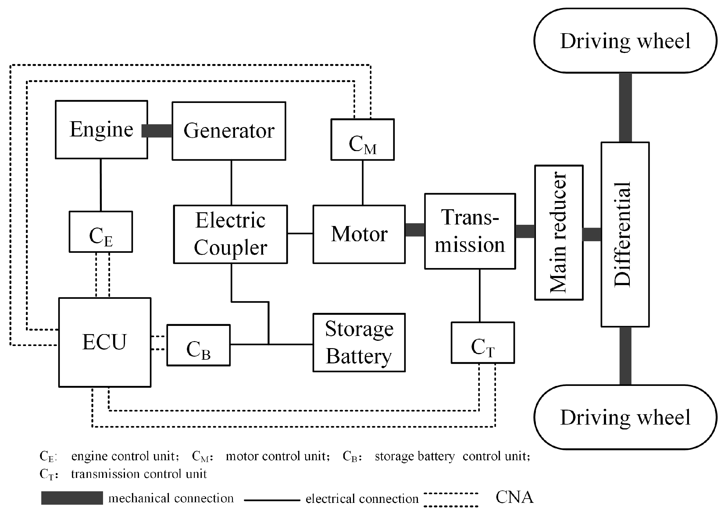
2. Power System Structure Design and Parameter Selection

The power system structure of the studied series diesel–electric hybrid tractor is illustrated in Figure 1. The vehicle’s power system primarily comprises an engine, a generator, a motor, and a storage battery. The engine is mechanically connected to the generator, providing a unidirectional power source. The storage battery is electrically connected to the motor via an electric coupler, enabling a bidirectional power source. The vehicle is capable of operating in four distinct modes, each with its own energy flow paths, which are as follows:
  • Pure electric driving mode: Storage Battery → Electric Coupler → Motor → Transmission Device → Driving Wheel.
  • Pure engine driving mode: Engine → Generator → Electric Coupler → Motor → Transmission Device → Driving Wheel.
  • Hybrid driving mode: Engine → Generator → Storage Battery → Electric Coupler → Motor → Transmission Device → Driving Wheel.
  • Driving with charging mode: The energy flows in two ways. Driving mode: Engine → Generator → Electric Coupler → Motor → Transmission Device → Driving Wheel; Charging mode: Engine → Generator → Electric Coupler → Storage Battery.
In agricultural production, plowing is considered the most fundamental and demanding working mode [18]. Therefore, the power requirements for plowing operations serve as the benchmark. In accordance with the drive system design method outlined in references [19,20], a 45-horsepower tractor was taken as the reference object, and the parameters of the main vehicle components were determined, as presented in Table 1. The universal characteristic curve of the engine is shown in Figure 2, and the efficiency map of the motor is shown in Figure 3.

3. Control Strategy

The rule-based ESOPCS offers the advantages of simplicity and straightforward implementation. To meet the actual working requirements of the tractor, Fuzzy PID control is used to achieve engine switching between multiple speed operating points. To further enhance the control effectiveness and fuel economy of the tractor, this paper proposes using the APSO algorithm to optimize the key parameters of multi-operating point Fuzzy PID controller.

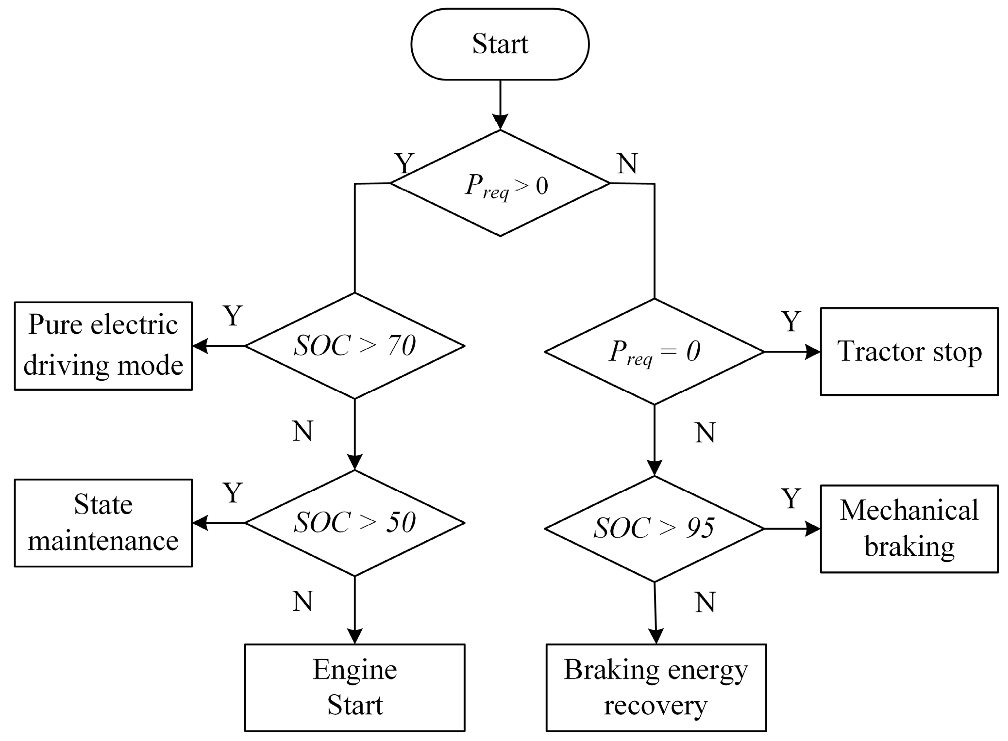
3.1. The Rule-Based Control Strategy

Referring to the engine’s universal characteristic diagram, the speed point on the optimal fuel economy curve is selected as the fixed-operating point for engine control. In the ESOPCS, by controlling the engine’s operating speed or output power, it can function in the high-efficiency region, thereby effectively improving the whole vehicle’s fuel economy. According to the diagram of engine universal characteristic, the rated speed of 2400 r/min is selected as the fixed operating point, where the engine output power is 25 kW, and the vehicle state control is shown in Figure 4.
As shown in Figure 4, when the vehicle’s required power Preq > 0 and the storage battery SOC (state of charge) > 70%, the engine is in the OFF stage. During this phase, the tractor is in pure electric driving mode, with the motor providing the power required for vehicle driving and operation. When the storage battery SOC < 50%, the engine enters the START stage and outputs constant power to meet the power needs of the vehicle. If the storage battery 50% ≤ SOC ≤ 70%, the engine remains in the state maintenance stage, meaning that it will maintain the state of the previous moment. When the vehicle’s required power Preq = 0, the vehicle is in a stopped state, and the engine stops working. When the vehicle’s required power Preq < 0 and the storage battery SOC > 95%, in order to avoid overcharging the battery, the vehicle enters in the mechanical braking state. Otherwise, the vehicle enters the regenerative braking state to recover braking energy.

3.2. MOPFPCS

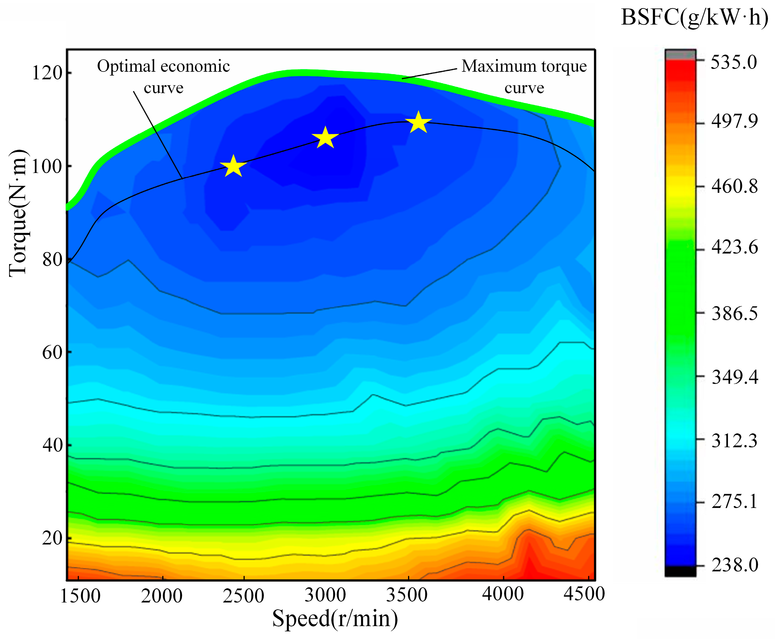
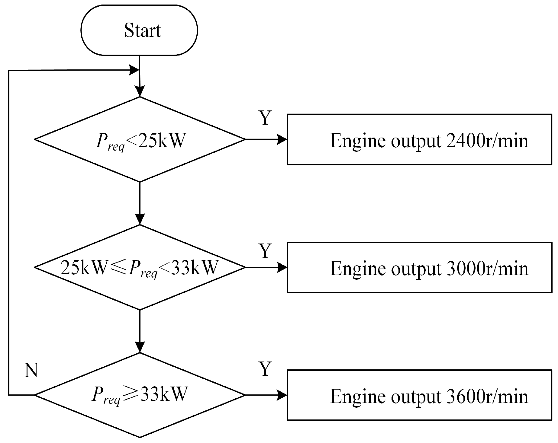
3.2.1. Determination of Multi-Operating Point

The ESOPCS limits the engine’s output power, making it difficult to meet the vehicle’s power demands under complex operating conditions. The MOPFPCS can select different engine speeds according to the power needs of the vehicle at different times, leading to the output of corresponding stable power and reducing unnecessary power output. However, too many operating points will lead to frequent engine speed switching, reducing fuel efficiency and increasing control complexity. Taking all these factors into consideration, this study identifies three high-efficiency operating points for the engine, namely 2400 r/min, 3000 r/min and 3600 r/min. The corresponding engine output power levels are 25 kW, 33 kW and 42 kW, respectively, as shown in Figure 2. Additionally, the Fuzzy PID controller is used to control the selected operating points. This strategy strikes a balance between improving fuel economy and reducing control complexity, effectively meeting the performance requirements of the vehicle under different power demands. The control logic diagram is shown in Figure 5.
As shown in Figure 5, when the motor power demand Preq < 25 kW, the engine maintains constant speed of 2400 r/min. When the motor power demand is 25 kW ≤ Preq < 33 kW, the engine maintains constant speed of 3000 r/min. And when the motor power demand is Preq ≥ 33 kW, the engine maintains constant speed of 3600 r/min. This control strategy adjusts the engine’s operating point to meet different power requirements, ensuring that the engine can provide the required power output at a stable speed.

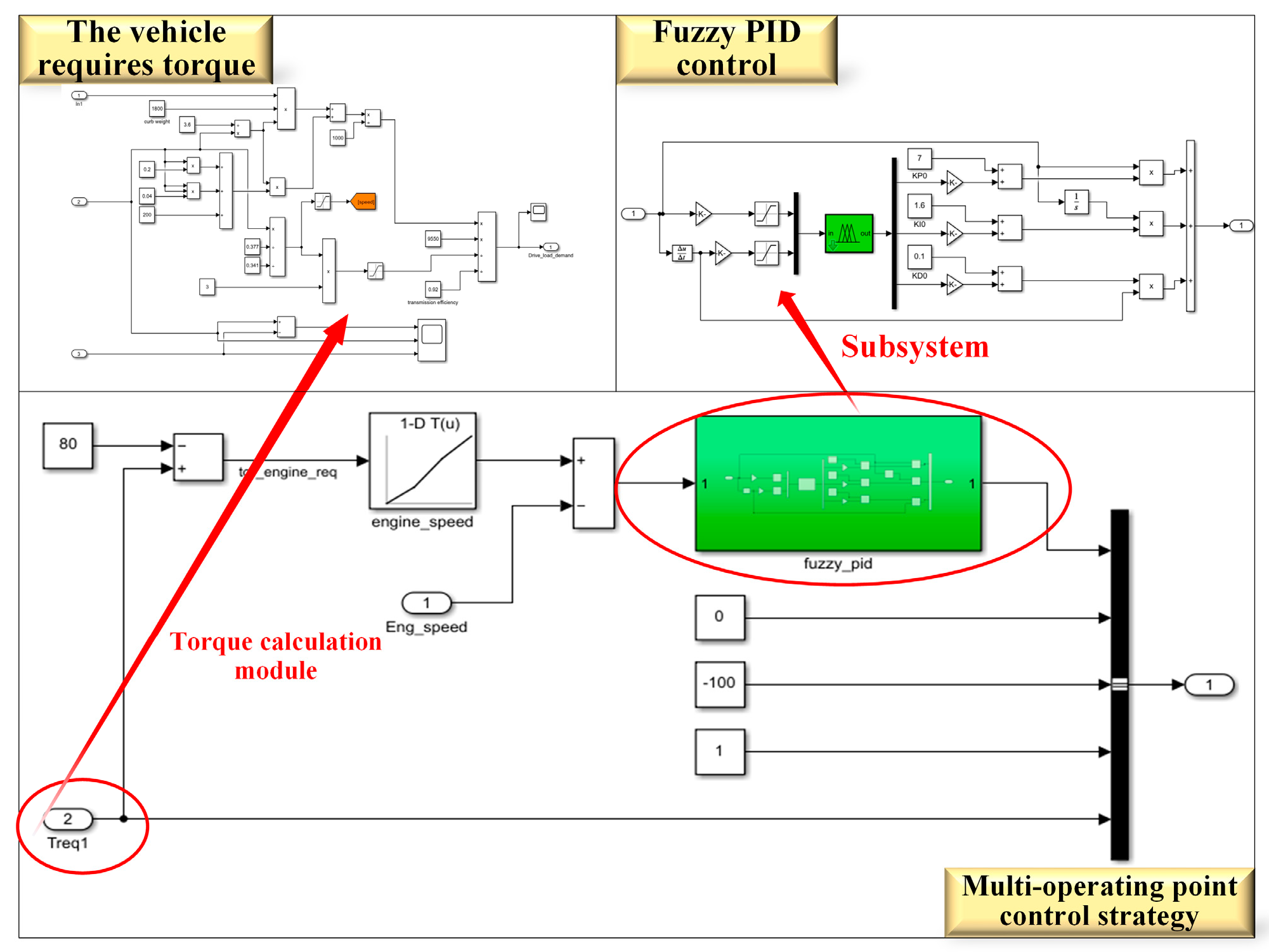
3.2.2. Fuzzy PID Control

Fuzzy PID control quantifies the system’s deviation e and deviation rate ec as input variables to the controller, uses fuzzy rules to modify PID parameters, and finally obtains output variables Δ K p , Δ K i and Δ K d through defuzzification using a proportional factor. The control deviation e ( t ) consists of the expected value and the actual feedback value, which is expressed as follows:
e ( t ) = x t a r ( t ) x a c t ( t )
where x t a r ( t ) is the given target speed of the engine and x a c t ( t ) is the actual speed of the engine.
In this paper, the PID controller adopts the incremental PID control algorithm [21], which is expressed as follows:
K α = K α 0 + Δ K α ( α = p , i , d )
Δ y t = K p ( e ( t ) e ( t 1 ) ) + K i e ( t ) + K d ( e ( t ) 2 e ( t 1 ) + e ( t 2 ) )
y ( t ) = y ( t 1 ) + Δ y t ( t )
where K α 0 is the basic parameters of the conventional PID model.
Considering the actual operating conditions of the engine, this study adopts a dual-input, three-output fuzzy controller. The input variables are engine speed deviation e and deviation rate ec, while the output variables are the parameter deviations of the PID control Δ K p , Δ K i and Δ K d . The triangular membership function [22] is used for both input and output. Seven fuzzy language variables are defined as {NB, NM, NS, ZO, PS, PM, PB}. Taking the input variable e as an example, the affiliation function is shown in Figure 6.
Fuzzy control rules can realize the adaptive adjustment of PID. In this paper, according to the reference adjusting parameters principle [23], the fuzzy control rules library is shown in Table 2, and the fuzzy rule output surface is shown in Figure 7.
  • When |e| is large, to improve the system response speed, Kp should be increased. Simultaneously, to avoid excessive integral saturation, Kd should be decreased, and Ki is often set to 0.
  • When |e| is moderate, to reduce the system overshoot, it is common to decrease Kp. and Ki can be appropriately increased to enhance the system’s regulation accuracy.
  • When |e| is small, to improve system stability, Kp and Ki should be increased. Simultaneously, Kd should select a moderate value to prevent system oscillations near the equilibrium point.

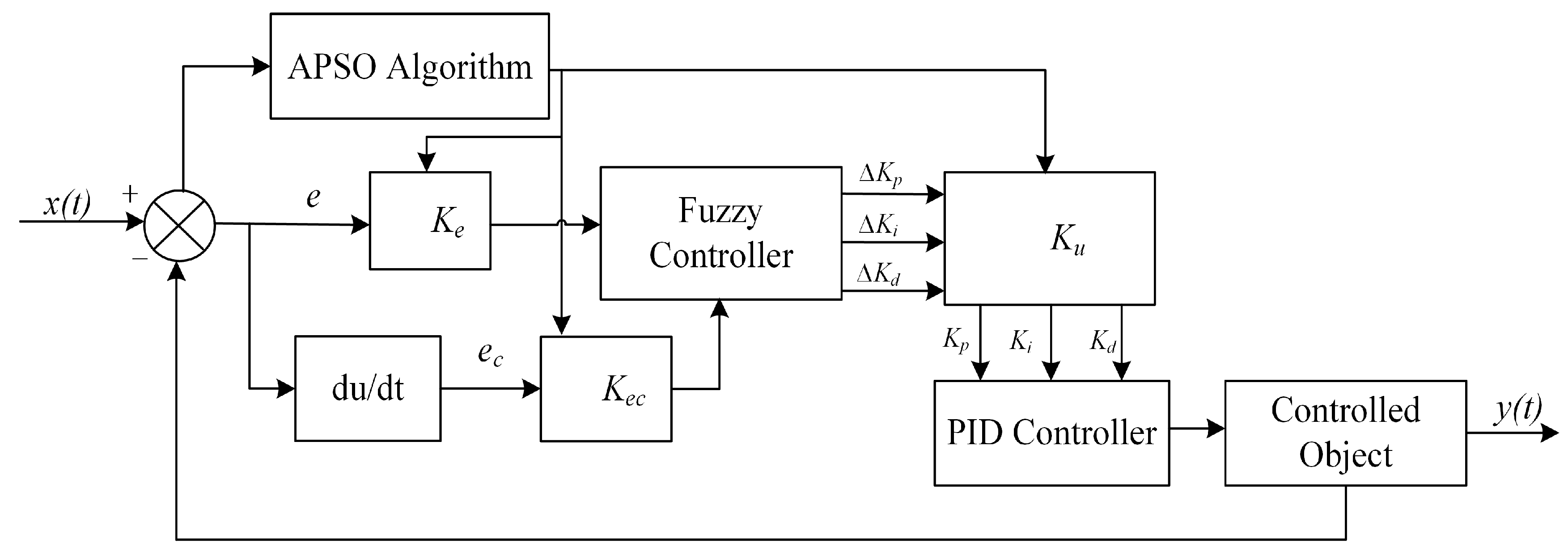
3.3. APSO-Optimized Fuzzy PID Controller

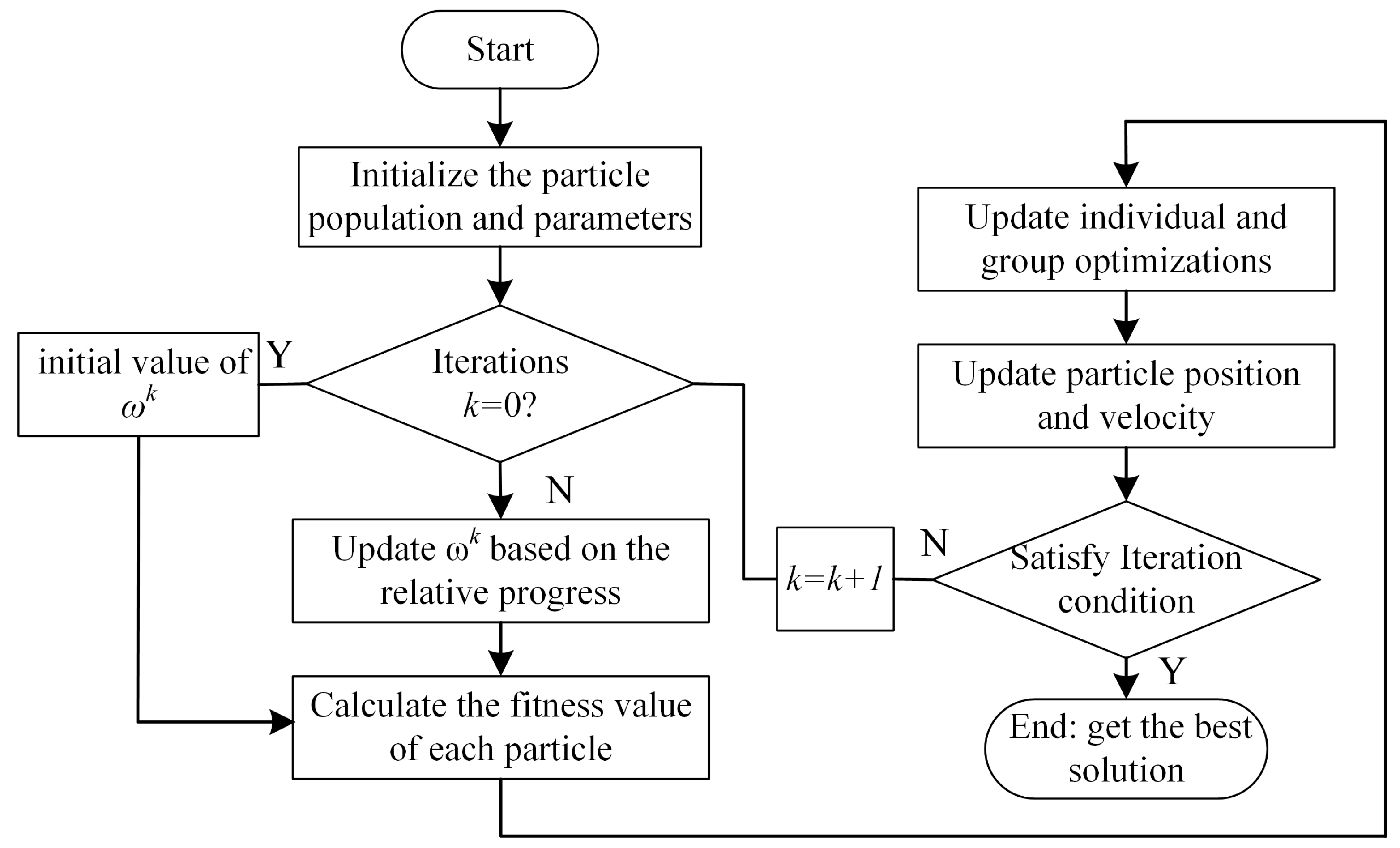
3.3.1. APSO Algorithm Principle

The standard PSO algorithm suffers from two major issues: convergence speed and local minimum. In contrast, the adaption particle swarm optimization (APSO) algorithm searches with the average velocity of particles following a cosine function pattern [24]. This ensures that in the initial search, the particle maintains a large value for an extended period, which is conducive to improving the efficiency, while in the later stage of searching, the particle maintains a small value for an extended period, which is conducive to improving the accuracy and effectiveness. This effectively solves the limitations of the standard PSO algorithm. The expression of the ideal particle velocities are as follows:
v i d e a l t = v s t a r t 1 + cos ( t T e n d ) 2
v s t a r t = x max x min
T e n d = 0.9 T max
where v i d e a l t is the ideal velocity of the particle at iteration t times; v s t a r t is the initial velocity of the particle’s ideal velocity; and x min and x max are the upper and lower limits of the decision variable, respectively. T e n d is the number of iterations in the cosine-varying stage of the ideal velocity, and T max is the maximum number of iterations.
The average absolute value of PSO velocity can be expressed as:
v a v e t = 1 N D i = 1 N j = 1 D v i j t
where v a v e t is the average absolute velocity of particle swarm iteration t times.
Inertia weight ω has the ability to balance global and local search, and its value has an important effect on the current flight speed of particles. In this paper, the inertia weight ω is dynamically adjusted according to the number of iterations k, which is expressed as follows:
ω k = ω max ( ω max ω min ) K k
where K is the maximum number of iterations; ω max is the upper limit of inertia weight; and ω min is the lower limit of inertia weight.

3.3.2. APSO-Optimized Fuzzy PID

In this paper, the APSO algorithm is used to optimize three parameters of Fuzzy PID, namely the input variable quantization factor Ke, Kec, and the output variable scale factor, Ku. The control principle is shown in Figure 8.
In the APSO algorithm, the dimension D = 3 and the optimized parameter is ϑ = [ K e , K e c , K u ] . Set the particle swarm size to 30, the maximum number of iteration to 200, the learning factor to c 1 = c 2 = 2, and the inertia weight to Formula (9), where ω max = 0.9 and ω min = 0.4. The product of the absolute value of time and error is selected as the fitness function, which is expressed as follows:
J = 0 t e ( t ) d t
where e ( t ) is the control deviation and J is the current fitness of the particle. For J , the smaller the fitness, the higher the optimization effect, which is better. The algorithm flow is shown in Figure 9.
The APSO iteration curve is shown in Figure 10, and the parameter optimization results are shown in Table 3.

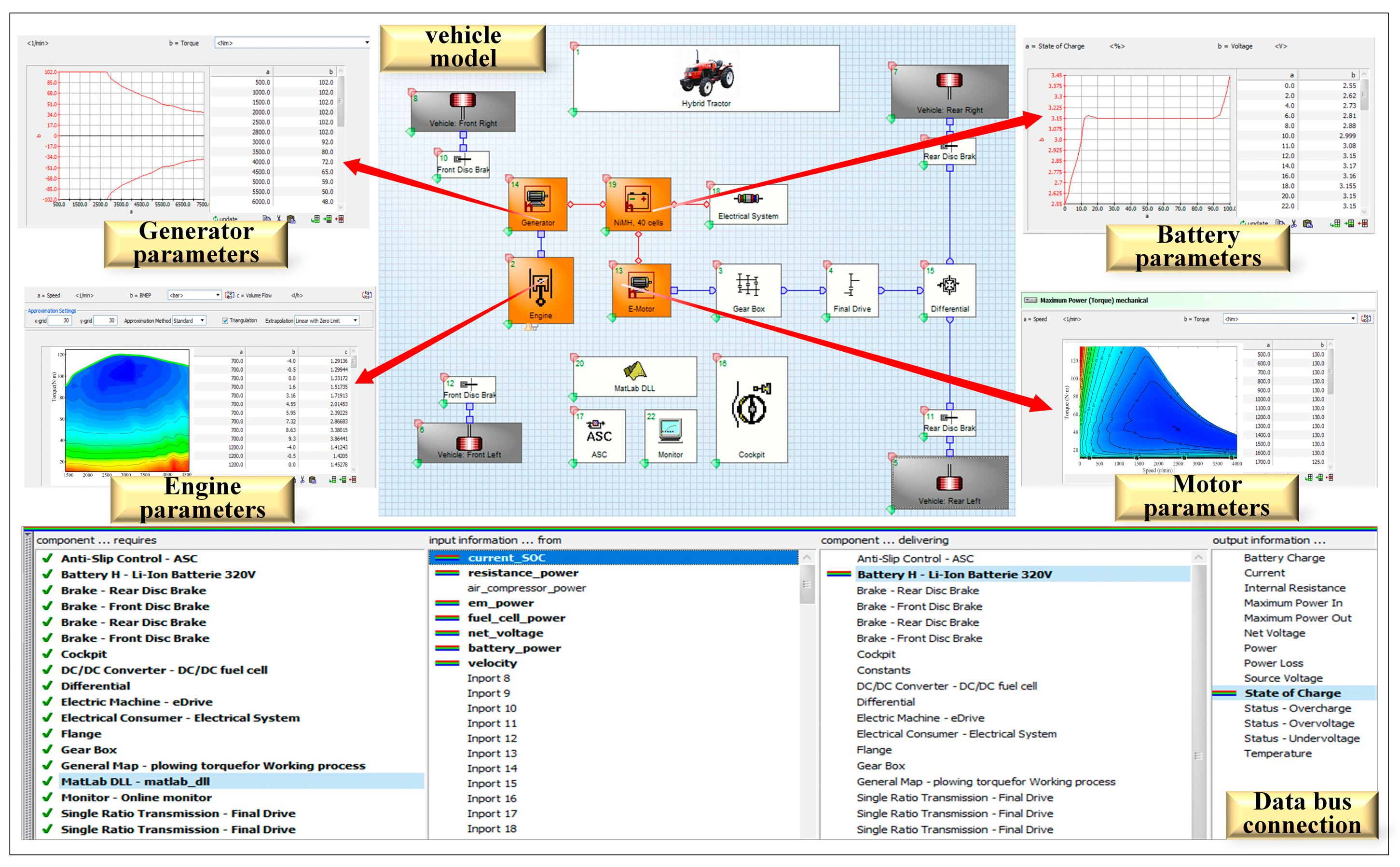
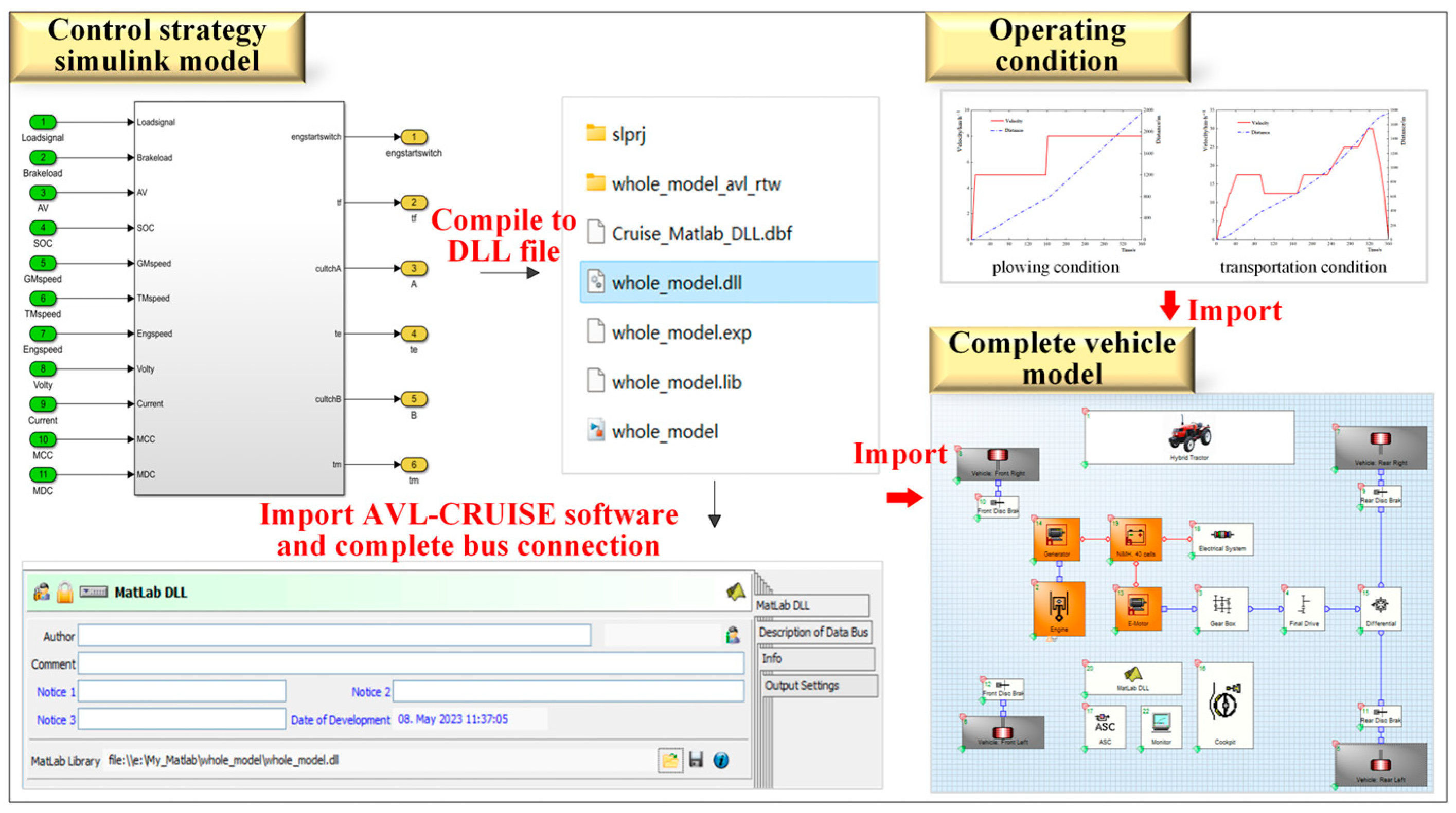
4. Modeling and Simulation

4.1. Simulation Model

Reasonable and effective vehicle modeling is a prerequisite for studying control strategy [25,26,27]. In this study, based on the vehicle structure and corresponding parameter selection shown in Figure 1, importing engine and motor data into AVL-Cruise simulation software and completing bus connection, the whole vehicle simulation model of serial diesel–electric hybrid tractor is established, as shown in Figure 11.
The control strategies of ESOPCS and MOPFPCS are constructed in the Matlab/Simulink environment, as depicted in Figure 12 and Figure 13. Then, the newly optimized parameters obtained from the APSO algorithm are input into the MOPFPCS to generate the APSO-MOPFPCS. These are compiled into DLL files, respectively, and imported into AVL-Cruise software to complete the bus connection, thus realizing the joint simulation between Matlab/Simulink and AVL-Cruise software, as shown in Figure 14.
To verify the feasibility and effectiveness of the control strategy, this study conducts simulations for two working modes of the tractor, as shown in Figure 15. Under the plowing mode, the initial battery SOC is set to 57%, the maximum vehicle speed is 8 km/h, and the simulation time is 360 s. The transport working mode is set in the full load state of the tractor, in accordance with the EUDC_Man standard working conditions, and considering actual tractor operation, the speed is set to 0.25 times the original condition, the initial battery SOC is set to 48%, the maximum transportation speed is 30 km/h, and the simulation time is 360 s.

4.2. Simulation Result Analysis

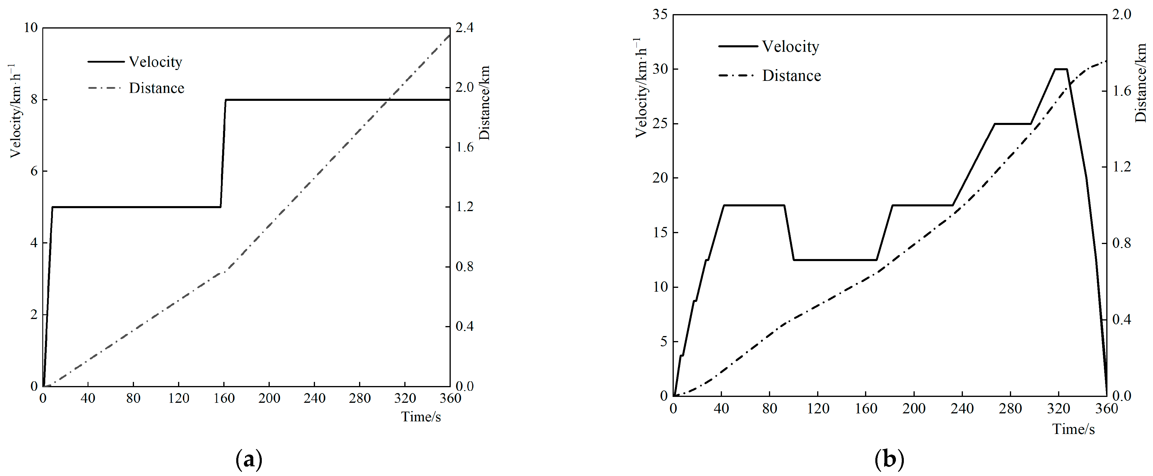
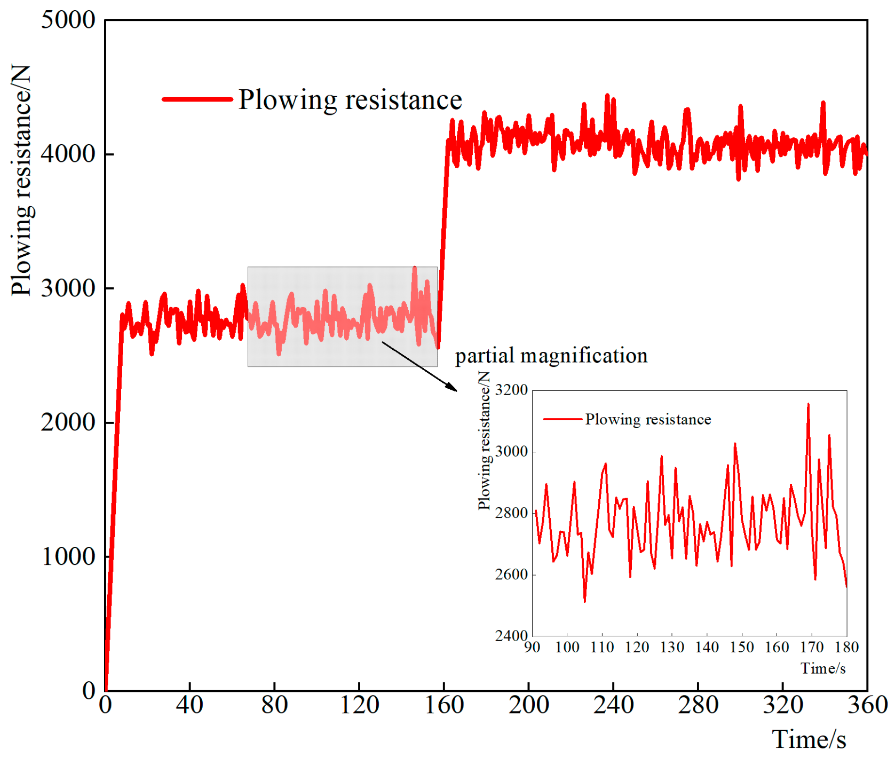
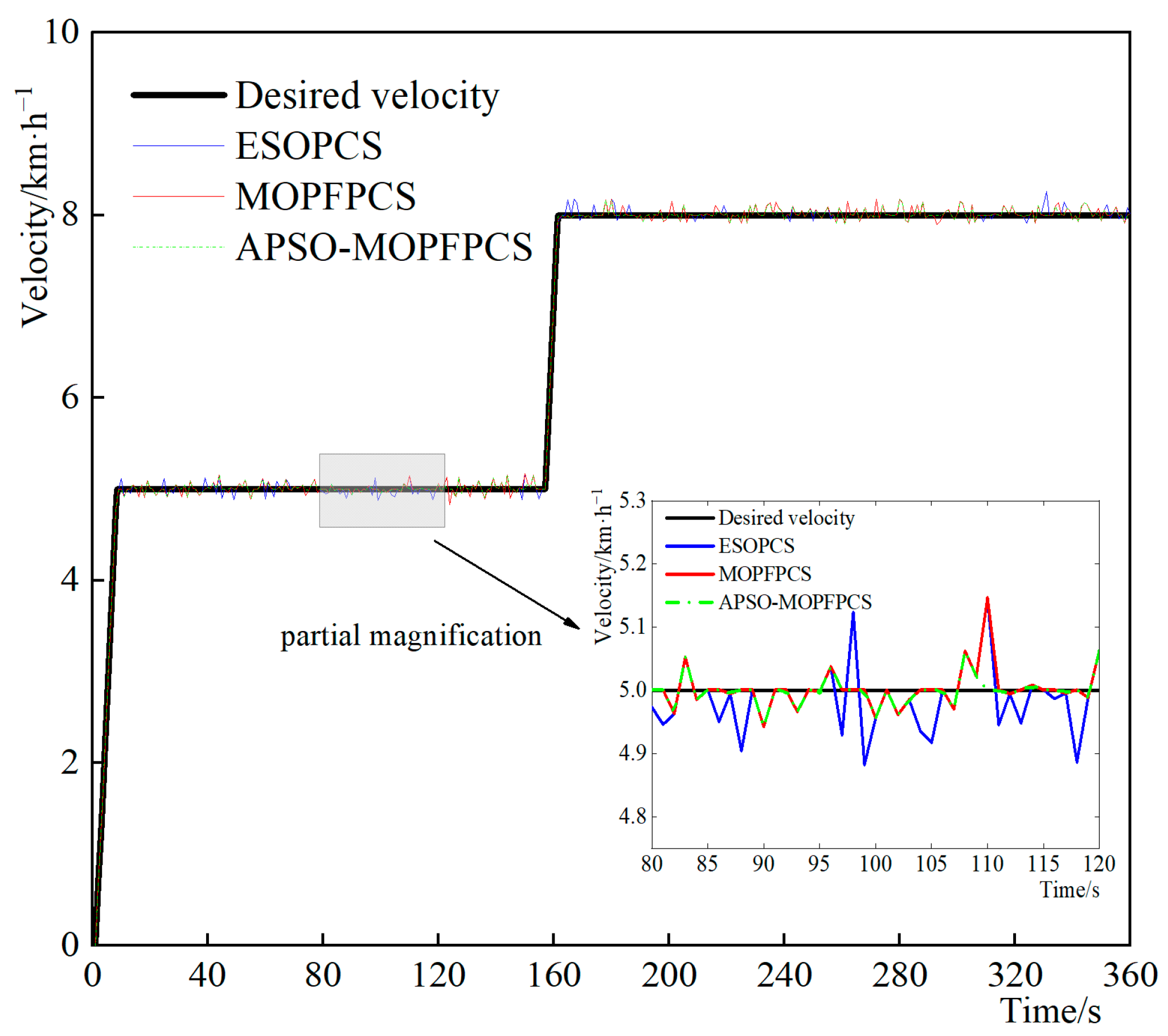
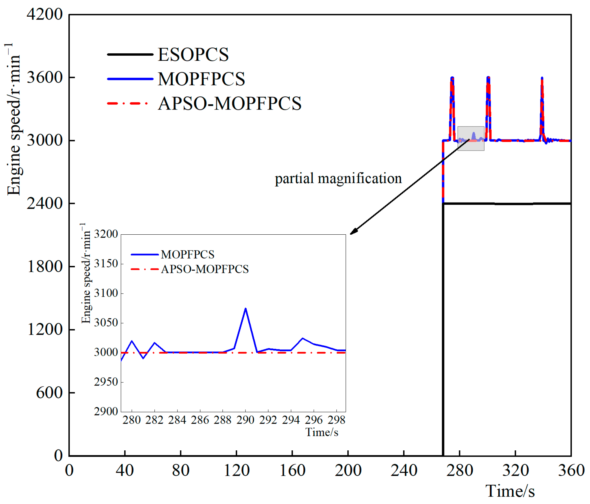
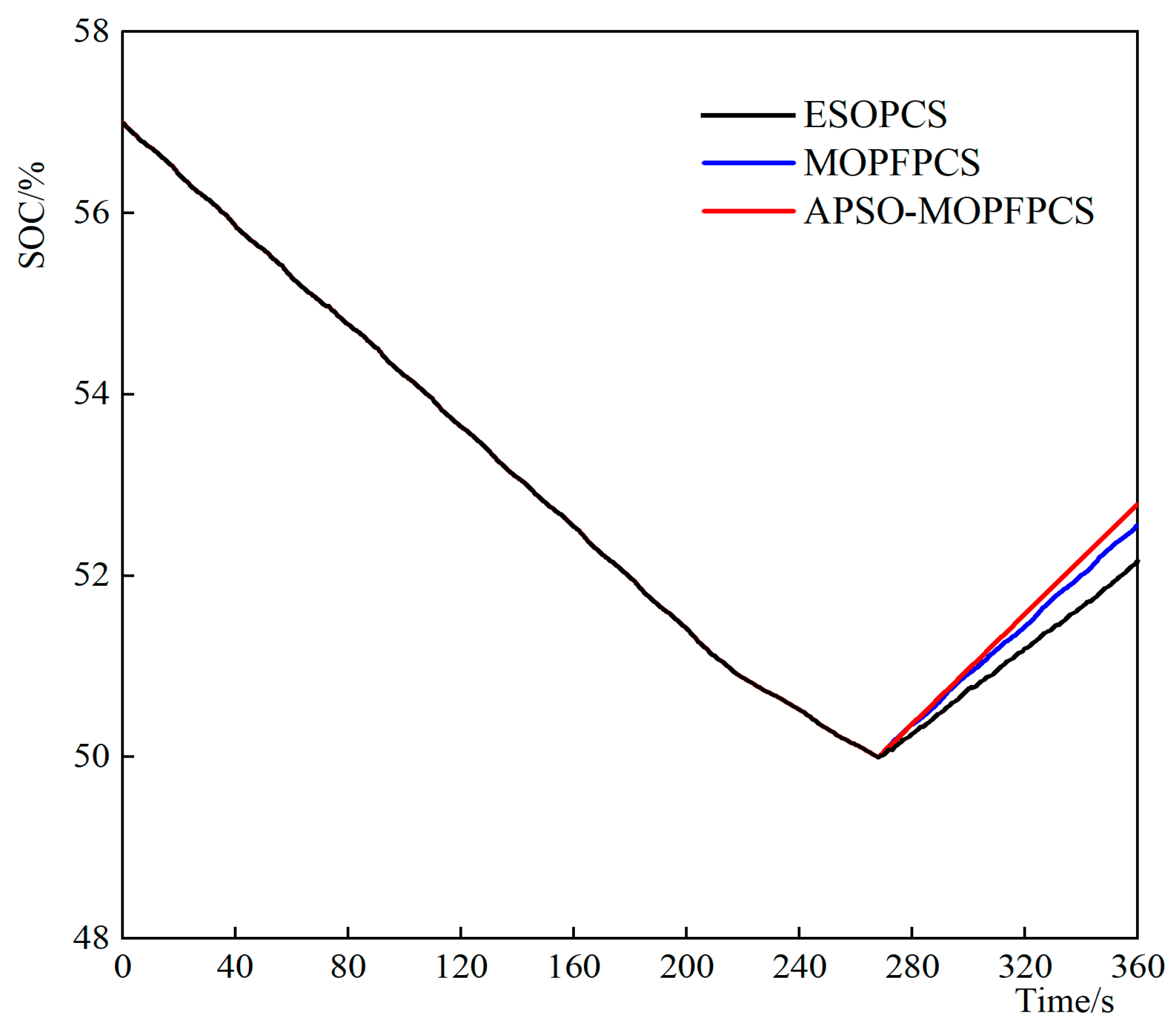
4.2.1. The Plowing Condition

Under the plowing condition, the tractor is set to maintain a constant speed, while the plowing resistance conditions varied, as outlined in Table 4, with depths of 12 cm and 20 cm, respectively. The plowing resistance is shown in Figure 16.
When the tractor is plowing, under the three control strategies, the following velocity is shown in Figure 17, the variation of engine speed is shown in Figure 18, the variation of battery SOC is shown in Figure 19, and the equivalent fuel consumption is shown in Table 5.
As shown in Figure 17, during plowing operations, the tractor is able to maintain the target velocity stably under the three control strategies. However, due to the influence of Gaussian distributed random loads on the vehicle during plowing, the actual speed fluctuates within a small range, and the difference in fluctuation lies between [−0.3127, 0.3328].
As shown in Figure 18, after 268 s, the engine starts working. Under the ESOPCS, the engine speed remains at 2400 r/min, enabling a stable power output of 25 kW. Under the MOPFPCS, due to the fluctuation of the plowing load, the instantaneous power demand of the vehicle exceeds 33 kW at certain points. As a result, the engine speed switches between 3000 r/min and 3600 r/min. Compared with MOPFPCS, the APSO-MOPFPCS is more precise, ensuring a smooth transition of the engine speed between 3000 r/min and 3600 r/min.
As shown in Figure 19, the initial SOC of the battery is 57%. The initial SOC of the battery is 57%. During vehicle operation, the engine remains previously closed, the vehicle enters pure electric driving mode, and the battery SOC decreases steadily. After 268s, the battery SOC reaches the lower limit and the engine starts to recharge the battery while meeting the vehicle demand. At the end of the operation, the remaining battery SOCs under the three control strategies are 52.2%, 52.6%, and 52.8%, respectively.
As shown in Table 5, of the three control strategies, the APSO-MOPFPCS has the best performance in equivalent fuel consumption, saving 18.3% of fuel compared with the ESOPCS and 9.5% compared with the MOPFPCS.

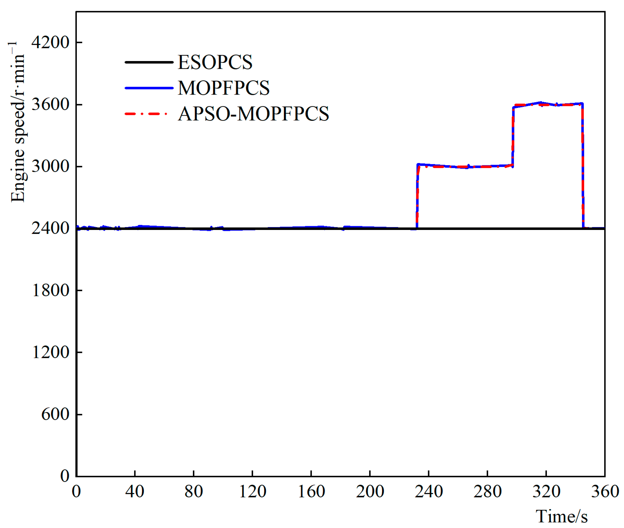
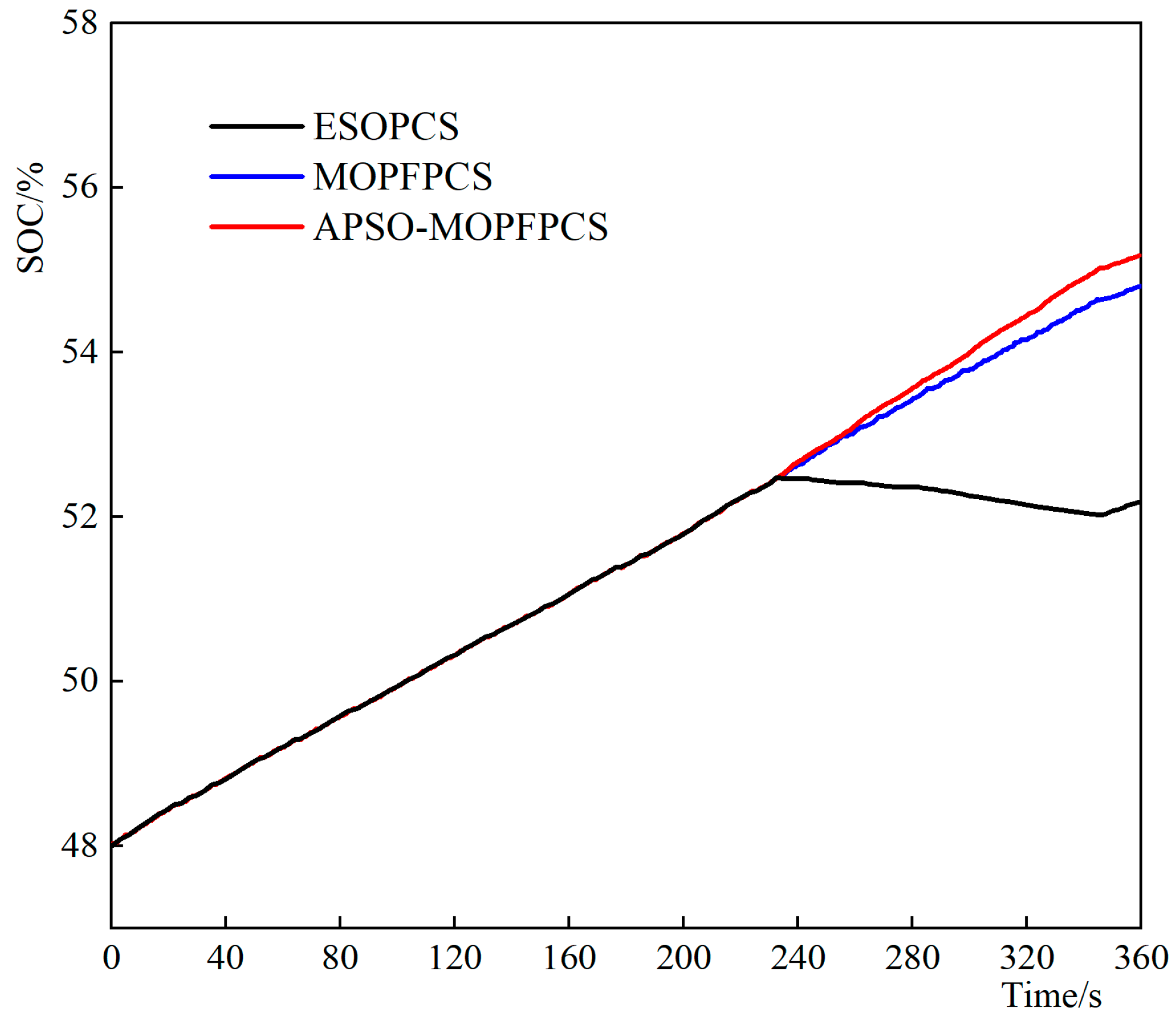
4.2.2. The Transportation Condition

When the tractor is transporting, under the three control strategies, the following velocity is shown in Figure 20, the variation of engine speed is shown in Figure 21, the variation of the battery SOC is shown in Figure 22, and the equivalent fuel consumption is shown in Table 6.
As shown in Figure 20, during transportation operation, the velocity of the tractor is followed well under the three control strategies, which verifies the rationality of the vehicle modeling and operating conditions setting.
As shown in Figure 21, under the ESOPCS, the engine speed is continuously maintained at 2400 r/min, providing a stable power output of 25 kW to propel the vehicle. Under the MOPFPCS, due to the specific transportation conditions, the engine speed undergoes three stages: 2400 r/min, 3000 r/min, and 3600 r/min before 345 s. After 345 s, the vehicle velocity gradually decreases to zero, causing the engine speed to drop back to 2400 r/min, consistent with the ESOPCS. The APSO-MOPFPCS has a better effect. Compared with the former, the engine speed can be smoothly switched between 2400 r/min, 3000 r/min, and 3600 r/min, while maintaining minimal control deviation.
As shown in Figure 22, the initial SOC of the battery is 48%, indicating a low battery level. Before 232 s, the engine charges the battery while meeting the operation requirements of the vehicle. After 232 s, due to the continuous increase in the vehicle demand power, the engine output power under the ESOPCS cannot meet the transportation requirements. As a result, the vehicle switches to hybrid driving mode and the battery discharges. After 345 s, the vehicle decelerates and the excess energy is supplied to the battery. In contrast, under the MOPFPCS, since the engine speed can output different power levels based on the actual operational demands, the battery continues to charge. Under the APSO-MOPFPCS, the engine’s smooth output across different speed ranges and smooth transition between adjacent speed ranges lead to improved engine energy utilization, resulting in a stable charging efficiency for the battery. At the end of the operation, the remaining battery SOC under the three control strategies are 52.2%, 54.8%, and 55.2%, respectively.
As shown in Table 6, the APSO-optimized multi-operating point Fuzzy PID control strategy has the best performance in equivalent fuel consumption, saving 15.0% of fuel compared with the ESOPCS and 4.6% compared with the MOPFPCS.

5. Conclusions

(1)
This study focuses on the SDEHT as the research object. A vehicle simulation model is developed, and a method based on APSO-MOPFPCS is proposed. Additionally, this research designs ESOPCS and MOPFPCS for comparative analysis.
(2)
The results indicate that in the plowing mode, APSO-MOPFPCS achieves a reduction of 18.3% and 9.5% in equivalent fuel consumption compared to ESOPCS and MOPFPCS, respectively. Similarly, in the transportation mode, APSO-MOPFPCS demonstrates a reduction of approximately 15.0% and 4.6% in equivalent fuel consumption compared to the ESOPCS and MOPFPCS, respectively. These findings highlight the effectiveness of the proposed APSO-MOPFPCS.
(3)
The control strategy based on APSO-MOPFPCS can adjust the engine speed according to the actual power demand of the entire vehicle so that the engine can work in the high-efficiency zone, maintain power, and improve fuel economy at the same time.
This research can provide a reference for the further optimization of the control strategy for SDEHT.

Author Contributions

Conceptualization, L.X.; data curation, Y.W., Y.L. and J.Z.; formal analysis, L.X., Y.W. and J.Z.; investigation, M.L.; software, Y.W.; supervision, M.L.; validation, Y.L. and J.Z.; visualization, M.L.; writing—original draft, L.X.; writing—review and editing, Y.W. and Y.L. All authors have read and agreed to the published version of the manuscript.

Funding

This research was funded by the National Key Research and Development Program (2022YFD2001204); the National Agricultural Major Scientific and Technological Project (NK202216010401); the Henan Province Key Science and Technology Special Project (221100110800); and the China Machinery Industry Group Co., Ltd., Youth Science and Technology Fund (QNJJ-PY-2022-14).

Informed Consent Statement

Informed consent was obtained from all subjects involved in the study.

Data Availability Statement

No new data were created or analyzed in this study. Data sharing is not applicable to this article.

Conflicts of Interest

The authors declare no conflict of interest.

References

  1. He, K.; Wu, H.; Zeng, Y. Development of smart agriculture with goals of carbon peaking and carbon neutrality. J. Huazhong Agric. Univ. 2019, 42, 10–17. [Google Scholar]
  2. Xie, B.; Wu, Z.; Mao, E. Current Status and Prospects of Key Technologies for Agricultural Tractors. J. Agric. Mach. 2018, 49, 13–30. [Google Scholar]
  3. Ju, X. Application of Big Data Technology to Promote Agricultural Structure Adjustment and High-Quality Development of Modern Agriculture. Comput. Intell. Neurosci. 2022, 9, 5222760. [Google Scholar] [CrossRef] [PubMed]
  4. Zhang, Y. Research and Reflection on Hybrid Power for Tractors. Agric. Eng. Technol. 2021, 41, 56–57. [Google Scholar]
  5. Li, Y.; Liu, M.; Xu, L.; Lei, S. Control Strategy of Hybrid Power Tractors based on Nonlinear Programming Genetic Algorithm. J. Jiangsu Univ. (Nat. Sci. Ed.) 2023, 44, 166–172+185. [Google Scholar]
  6. Lu, X.; Wu, Y.; Lian, J. Energy management of hybrid electric vehicles: A review of energy optimization of fuel cell hybrid power system based on genetic algorithm. Energy Convers. Manag. 2020, 205, 112474. [Google Scholar] [CrossRef]
  7. Zhang, J.; Feng, G.; Liu, M.; Yan, X.; Xu, L.; Shang, C. Research on Global Optimal Energy Management Strategy of Agricultural Hybrid Tractor Equipped with CVT. World Electr. Veh. J. 2023, 14, 127. [Google Scholar] [CrossRef]
  8. Wang, Y.; Li, W.; Liu, Z.; Li, L. An Energy Management Strategy for Hybrid Energy Storage System Based on Reinforcement Learning. World Electr. Veh. J. 2023, 14, 57. [Google Scholar] [CrossRef]
  9. Li, W.; Feng, G.; Jia, S. An Energy Management Strategy and Parameter Optimization of Fuel Cell Electric Vehicles. World Electr. Veh. J. 2022, 13, 21. [Google Scholar] [CrossRef]
  10. Lü, X.; Li, S.; He, X.; Xie, C.; He, S.; Xu, Y.; Fang, J.; Zhang, M.; Yang, X. Hybrid Electric Vehicles: A Review of Energy Management Strategies Based on Model Predictive Control. J. Energy Storage 2022, 56, 106112. [Google Scholar] [CrossRef]
  11. Zhang, F.; Wang, L.; Coskun, S.; Pang, H.; Cui, Y.; Xi, J. Energy management strategies for hybrid electric vehicles: Review, classification, comparison, and outlook. Energies 2020, 13, 3352. [Google Scholar] [CrossRef]
  12. Wang, X.; Wang, Z.; Zhou, J. Study on Control Strategy of Tandem Hybrid Tractor Considering Battery Life Decay. J. Yunnan Agric. Univ. (Nat. Sci.) 2023, 38, 529–536. [Google Scholar]
  13. Xu, L.; Zhang, J.; Liu, M.; Zhao, Z.; Li, C. Control Algorithm and Energy Management Strategy for Extended Range Electric Tractors. Int. J. Agric. Biol. Eng. 2017, 10, 35–44. [Google Scholar]
  14. Luo, G. Research on Energy Management Strategy of Series Diesel-Electric Hybrid Tractor. Master’s Thesis, Nanjing Agricultural University, Nanjing, China, 2019. [Google Scholar]
  15. Zhang, J.; Feng, G.; Xu, L.; Wang, W.; Yan, X.; Liu, M. Energy-saving Control of Hybrid Power Tractor Based on Pontryagin’s Minimum Principle. Trans. Chin. Soc. Agric. Mach. 2023, 54, 396–406. [Google Scholar]
  16. Dou, H.; Zhang, Y.; Ai, Q.; Zhao, X. Control strategy for hybrid tractor plow conditions oriented to coupled-split dynamic configuration. Trans. Chin. Soc. Agric. Eng. 2022, 38, 41–49. [Google Scholar]
  17. Du, A.; Chen, Y.; Zhang, D.; Han, Y. Multi-Objective Energy Management Strategy Based on PSO Optimization for Power-Split Hybrid Electric Vehicles. Energies 2021, 14, 2438. [Google Scholar] [CrossRef]
  18. Shao, X.; Yang, Z.; Mowafy, S.; Zheng, B.; Song, Z.; Luo, Z.; Guo, W. Load Characteristics Analysis of Tractor Drivetrain under Field Plowing Operation Considering Tire-Soil Interaction. Soil Tillage Res. 2023, 227, 105620. [Google Scholar] [CrossRef]
  19. Xu, L.; Liu, M.; Zhou, Z. Design of Drive System for Series Hybrid Tractor. J. Agric. Eng. 2014, 9, 11–18. [Google Scholar]
  20. Liu, Y.; Deng, X.; Zhang, W.; Zhu, Y.; He, R. Design Theory and Method Research on Tandem Hybrid Tractor Drive System. Agric. Equip. Veh. Eng. 2018, 6, 49–54. [Google Scholar]
  21. Yang, Y.; Zhang, Q. Design of Particle Swarm Optimization-based Self-tuning Fuzzy-PID Controller. J. Mech. Manuf. Autom. 2018, 47, 201–204. [Google Scholar]
  22. Singh, R.; Vashishath, M.; Kumar, S. Ant Colony Optimization Technique for Edge Detection Using Fuzzy Triangular Membership Function. Int. J. Syst. Assur. Eng. Manag. 2019, 10, 91–96. [Google Scholar] [CrossRef]
  23. Li, S.; Zhou, J.; Xu, Y. Design of Precision Irrigation Control System based on PSO-Optimized Fuzzy-PID. Water-Sav. Irrig. 2019, 3, 90–93. [Google Scholar]
  24. Zou, S.; Zhao, W. Energy Optimization Strategy of Vehicle DCS System Based on APSO Algorithm. Energy 2020, 208, 118404. [Google Scholar] [CrossRef]
  25. Liu, M.; Li, Y.; Zhao, S.; Han, B.; Lei, S.; Xu, L. Multi-Objective Optimization and Test of a Tractor Drive Motor. World Electr. Veh. J. 2022, 13, 43. [Google Scholar] [CrossRef]
  26. Ataei, M.; Khajepour, A.; Jeon, S. Development of a novel general reconfigurable vehicle dynamics model. Mech. Mach. Theory 2021, 156, 104147. [Google Scholar] [CrossRef]
  27. Du, C.; Gan, W.; Zhang, P.; He, J. Modeling of Vehicle Control Strategy and Hardware-in-the-Loop Simulation for Hybrid Electric Vehicles. Automot. Technol. 2016, 12, 31–36. [Google Scholar]
Figure 1. Diagram of the series hybrid tractor power system structure.
Wevj 14 00258 g001
Figure 2. Diagram of the engine’s universal characteristics.
Wevj 14 00258 g002
Figure 3. Diagram of motor efficiency.
Wevj 14 00258 g003
Figure 4. Diagram of vehicle state control.
Wevj 14 00258 g004
Figure 5. Diagram of multi- operating point control logic block.
Wevj 14 00258 g005
Figure 6. Affiliation function of deviation e.
Wevj 14 00258 g006
Figure 7. (a) The fuzzy rule output surface of ΔKp; (b) the fuzzy rule output surface of ΔKi; (c) the fuzzy rule output surface of ΔKd.
Wevj 14 00258 g007
Figure 8. Schematic diagram of APSO-optimized Fuzzy PID controller.
Wevj 14 00258 g008
Figure 9. Flow chart of APSO algorithm.
Wevj 14 00258 g009
Figure 10. Curve of APSO iteration.
Wevj 14 00258 g010
Figure 11. Model of the complete vehicle.
Wevj 14 00258 g011
Figure 12. Model of ESOPCS.
Wevj 14 00258 g012
Figure 13. Model of MOPFPCS.
Wevj 14 00258 g013
Figure 14. Diagram of co-simulation.
Wevj 14 00258 g014
Figure 15. (a) Diagram of plowing condition; (b) diagram of the transportation condition.
Wevj 14 00258 g015
Figure 16. Plowing resistance.
Wevj 14 00258 g016
Figure 17. Diagram of following velocity under the plowing condition.
Wevj 14 00258 g017
Figure 18. Diagram of engine speed variation under the plowing condition.
Wevj 14 00258 g018
Figure 19. Diagram of battery SOC variation under the plowing condition.
Wevj 14 00258 g019
Figure 20. Diagram of following velocity under the transportation condition.
Wevj 14 00258 g020
Figure 21. Diagram of engine speed variation under the transportation condition.
Wevj 14 00258 g021
Figure 22. Diagram of battery SOC variation under the transportation condition.
Wevj 14 00258 g022
Table 1. Main parameters of the series hybrid tractor.
ProjectParameterValue
EngineMaximum power/kW60
Rated speed/(r/min)2400
Maximum torque/(N·m)120
GeneratorRated power/kW30
Rated speed/(r/min)1500
MotorRated power/kW25
Rated speed/(r/min)2000
Rated frequency/Hz50
Storage batteryRated voltage/V100
Rated capacity/Ah100
TransmissionOne-speed transmission ratio12
Two-speed transmission ratio8.45
Three-speed transmission ratio5.65
Four-speed transmission ratio3.2
Main speed reducerTransmission ratio3.5
Table 2. Fuzzy control rules library.
ΔKp/ΔKi/ΔKdE
NBNMNSZOPSPMPB
EcNBPB/NB/PSPB/NB/PSPM/NB/ZOPM/NM/ZOPS/NM/ZOPS/ZO/PBZO/ZO/ZO
NMPB/NB/NSPB/NB/NSPM/NM/NSPM/NM/NSPS/NS/ZOZO/ZO/PSZO/ZO/PM
NSPM/NM/NBPM/NM/NBPM/NS/NMPS/NS/NSZO/ZO/ZONS/PS/PSNM/PS/PM
ZOPM/NM/NBPS/NS/NMPS/NS/NMZO/ZO/NSNS/PS/ZONM/PS/PSNM/PM/PM
PSPS/NS/NBPS/NS/NMZO/ZO/NSNS/PS/NSNS/PS/ZONM/PM/PSNM/PM/PS
PMZO/ZO/NMZO/ZO/NSNS/PS/NSNM/PM/NSNM/PM/ZONM/PB/PSNB/PB/PS
PBZO/ZO/PSNS/ZO/ZONS/PS/ZONM/PM/ZONM/PB/ZONB/PB/PBNB/PB/PB
Table 3. Data of parameter optimization.
Optimization ObjectKeKecKu
Parameters before optimization0.6710.1240.426
Parameters after optimization0.8320.0850.691
Table 4. Plowing resistance conditions.
Time/sPlowing Velocity/(km/h)Plowing Depth/cm
8~157512
162~360820
Table 5. Equivalent fuel consumption under the plowing condition.
Control StrategyFuel Consumption/LBattery Initial SOC/%Battery Termination SOC/%Equivalent Fuel
Consumption/L
ESOPCS0.2645752.20.361
MOPFPCS0.2375752.60.326
APSO-MOPFPCS0.2115752.80.295
Table 6. Equivalent fuel consumption under the transportation condition.
Control StrategyFuel Consumption/LBattery Initial SOC/%Battery Termination SOC/%Equivalent Fuel
Consumption/L
ESOPCS0.9424852.20.858
MOPFPCS0.8984854.80.764
APSO-MOPFPCS0.8734855.20.729
Disclaimer/Publisher’s Note: The statements, opinions and data contained in all publications are solely those of the individual author(s) and contributor(s) and not of MDPI and/or the editor(s). MDPI and/or the editor(s) disclaim responsibility for any injury to people or property resulting from any ideas, methods, instructions or products referred to in the content.

