Article

Quad-Rotor Unmanned Aerial Vehicle Path Planning Based on the Target Bias Extension and Dynamic Step Size RRT* Algorithm

College of Electrical and Electronic Engineering, Anhui Science and Technology University, Bengbu 233030, China
*
Author to whom correspondence should be addressed.
World Electr. Veh. J. 2024, 15(1), 29; https://doi.org/10.3390/wevj15010029
Submission received: 12 December 2023 / Revised: 8 January 2024 / Accepted: 10 January 2024 / Published: 16 January 2024

Abstract

:
For the path planning of quad-rotor UAVs, the traditional RRT* algorithm has weak exploration ability, low planning efficiency, and a poor planning effect. A TD-RRT* algorithm based on target bias expansion and dynamic step size is proposed herein. First, random-tree expansion is combined with the target bias strategy to remove the blindness of the random tree, and we assign different weights to the sampling point and the target point so that the target point can be quickly approached and the search speed can be improved. Then, the dynamic step size is introduced to speed up the search speed, effectively solving the problem of invalid expansion in the process of trajectory generation. We then adjust the step length required for the expansion tree and obstacles in real time, solve the opposition between smoothness and real time in path planning, and improve the algorithm’s search efficiency. Finally, the cubic B-spline interpolation method is used to modify the local inflection point of the path of the improved RRT* algorithm to smooth the path. The simulation results show that compared with the traditional RRT* algorithm, the number of iterations of path planning of the TD-RRT* algorithm is reduced, the travel distance from the starting position to the end position is shortened, the time consumption is reduced, the path route is smoother, and the path optimization effect is better. The TD-RRT* algorithm based on target bias expansion and dynamic step size significantly improves the planning efficiency and planning effect of quad-rotor UAVs in a three-dimensional-space environment.

1. Introduction

Quad-rotor UAVs (unmanned aerial vehicles) are becoming more and more popular among the general public in recent years, and their flight status offers some advantages, such as the following: stable hovering characteristics [1], high maneuverability and agility [2], small size, simple mechanical structures, easy maintenance [3], precise identification, and obstacle avoidance in flight [4]. Therefore, they have received more extensive attention from and been the subject of more in-depth research by experts and scholars [5]. In the civil field, quad-rotor UAVs are used in many sectors, such as industry, agriculture, forestry, and so on [6,7], so they can cooperate with human beings to carry out inspection tasks involving electric power, high altitudes, and other situations. They can also help farmers to carry out spraying and fertilizing for plant protection. In the military field, they are mainly used for the patrol of the national defense boundary line [8], the inspection of battlefield ground, and the evaluation of battle results.
The autonomous navigation problem of quad-rotor UAVs can be divided into three processes: environment sensing, path planning, and motion control [9]. In this paper, the path-planning problem is studied in depth. Path planning consists of planning an optimal path from an initial position to an end position, with quad-rotor UAVs flying in the presence of obstacles on the terrain and the required constraints being met at the same time [10]. At present, the most common algorithms for path planning include Dijkstra’s algorithm [11], the A* algorithm [12,13,14], the Artificial Potential Field Method [15], the RRT (Rapid-exploring Random Trees) algorithm [16,17,18,19,20], and the RRT* algorithm [21,22,23,24,25], the last of which is progressively optimized for the RRT algorithm.
The Dijkstra algorithm was proposed by the Dutch computer scientist Edsger Wybe Dijkstra in 1959, so it is also called Dijkstra’s algorithm. The main feature of this algorithm is to start from a starting point and employ the strategy of the greedy algorithm from the optimal solution of each step to finally obtain the global optimal solution, each time traversing the adjacent node of the vertex that is closest to the starting point and has not been visited until it reaches the end point. The authors of [26] used Dijkstra’s algorithm for indoor navigation to locate objects and move them along the shortest path. The disadvantage is that this algorithm is more complex if the environment is too large. Originally presented in 1968 by Peter Hart, Nils Nilsson, and Bertram Raphael from the Stanford Institute, the A* algorithm can be considered an extension of the Dijkstra algorithm; it sets the weight for each edge length, constantly calculating the distance from each vertex to the starting vertex to obtain the shortest route, as well as exploiting the advantage of constantly advancing toward the target as directed by the greedy best-priority-search algorithm so as to search for fewer vertices and keep the search path efficient. In [27], in order to solve the problems of long computation times and large memory occupation in collaborative tasks of quad-rotor UAV obstacle avoidance path-planning algorithms, the authors propose a method combining the A* algorithm and the task allocation algorithm to create a fast and effective path-planning method. The disadvantage in this case is that when there are many targets, a large number of duplicate data and complex valuation functions are introduced. The artificial potential field method was proposed by Khatib in 1986, and its basic idea is to construct a repulsive potential field around an obstacle and a gravitational potential field around the target point. The controlled object is subjected to repulsive and gravitational forces in the composite field composed of these two potential fields, and the combined force of the repulsive and gravitational forces guides the movement of the controlled object, allowing for a search for the obstacle avoidance path without touching any obstacles. In [28], an artificial potential field method was introduced to position a local attractor around an obstacle, thereby guiding the robot employed around the preferred region. The zero-potential-energy point is its fatal shortcoming; it causes the agent to fall into local minima, meaning that the agent cannot achieve path planning when it cannot proceed to the minimum. The rapidly exploring random trees (RRT) algorithm was proposed by Prof. Steven M. LaValle of Iowa State University [29]; it has a powerful and flexible search and processing capability and is applied to complex environment path planning. Through the comparison of these path plans, combined with the overly complex terrain of quad-rotor UAVs’ flight environments, the RRT algorithm finds only a feasible path; it cannot obtain the optimal path. We optimized it using the RRT* algorithm, and after each iteration of the route plan, the entire search tree was reworked to optimize the route. In [30], target heuristics were added, and the dynamics constraints of quad-rotor UAVs were fused to generate a flyable path. By pruning and reconstructing the original random tree when the surrounding environment changed abruptly, the convergence speed of the quad-rotor UAVs for adjusting and re-planning the route was accelerated, but the algorithm’s adaptability was poor. In [31], an AI-RRT* (Anytime-Informed RRT*) algorithm was designed; it performs path planning online at any time and adds the heuristic selection of rolling programming sub-goals. It also suffers from problems such as poor adaptability. In [32], a TRH-RRT* (three-dimensional rapidly exploring random tree* based on receding horizon) path-planning algorithm was proposed; it uses partial random samples to improve the utilization efficiency of sampling points, and the researchers combined the artificial potential field method with the RRT* algorithm to inspire node growth and reduce the unnecessary scanning process. In [33], an RRT* forest algorithm was designed to improve the path-planning efficiency of quad-rotor UAVs in a complex terrain environment by randomly selecting root nodes, generating random trees, connecting random trees, and merging random trees. In [34], the authors propose an improved method based on adaptive target bias and heuristic cyclic sampling. The adaptive target bias function method was used to make the random trees continuously approach the target point; then, a method combining heuristic cyclic sampling and the direction deviation strategy is designed to resample the nodes next to obstacles. In [35], the authors propose a path-planning algorithm named RRT*Smart-AD; it satisfies the two characteristics of obstacle avoidance constraints and dynamic characteristics in a dynamic environment. In [36], the authors propose an upgrade-based RRT* algorithm. By limiting the generation of random sampling points in the variable region, the number of path-planning iterations can be reduced. Then, the improved APF (Artificial Potential Field) method is introduced into the RRT* algorithm to improve its convergence speed. Finally, the cubic B-spline algorithm is used to optimize the path. In [37], the authors propose an algorithm based on PF-RRT*. First, the dichotomy method was used to re-establish a new parent node near an obstacle, and then the improved APF (Artificial Potential Field) method is established to repel obstacles while it moves towards the target point. At the same time, it was combined with the target bias strategy to enhance the guiding effect for the target. In [38], the authors propose an improved RRT* algorithm named F-RRT*, which can find a good initial solution and exhibits good convergence speed. The F-RRT* algorithm optimizes the path cost for creating a parent node for random points. In [39], the authors propose the TSRRT* algorithm; it expands new nodes through a variety of sampling methods and cost evaluation, and then it optimizes the new nodes with the time coordination cost function, so it can improve the efficiency of path planning.
Through the summary of all the references, the RRT* algorithm further optimizes the path, but it still suffers from some shortcomings. As the number of iterations increases, the overall path cost is always as low as possible. However, with the increase in the number of iterations, the number of computations the algorithm must perform increases, and the algorithm planning time increases. Due to the special environment presented by complex terrain, the RRT* algorithm suffers from some problems such as high memory occupation and low planning efficiency [40]. Therefore, this paper proposes a Target bias extension and Dynamic step size RRT* algorithm named the TD-RRT* algorithm.
For the path-planning process of quad-rotor UAVs, an optimal path can be planned in both simple and complex environments: it consists of moving from the initial position to the target position without collisions [41]. For the planned path, quad-rotor UAVs can fly directly along its path, and they perform high-altitude work at the expected set points during the flight. The path-planning problems addressed herein involve three aspects:
  • When the path is planned, the RRT* algorithm suffers from slow convergence speed and poor target orientation;
  • In a complex terrain environment, due to the fixed expansion step size, the path of the quad-rotor UAVs cannot be dynamically adjusted, resulting in the failure of the RRT* algorithm to determine the optimal path, and the path planning will be sustainably inefficient;
  • The flight path is tortuous during path planning, and it must meet the kinematic constraints for the quad-rotor UAVs to fly smoothly.
Through the study of the above problems, an RRT* algorithm based on target bias expansion and dynamic step size was designed, and the specific measures taken are as follows:
  • During path searches, the probability threshold should be changed, and the range areas near the target point should be set as the target bias, thus allowing the algorithm to adapt to different environments while strengthening its target-oriented nature.
  • We adjust the step size of the quad-rotor UAVs through obstacles in a complex terrain environment in real-time. When path searching begins, the UAV is far away from the target point and the obstacles. A large step size and a fixed step size are used to search the path in order to improve the path-searching efficiency of the algorithm. When the UAV is close to the target point and the obstacles, the search expansion is carried out in small steps, guaranteeing that the UAV will not collide with any obstacles and arrive at the target point exactly.
  • For the polyline path, the B-spline curve interpolation method was used to smooth the path, allowing for the determination of the optimal flight path for quad-rotor UAVs.

2. Fundamentals of the RRT* Algorithm

In contrast to the RRT algorithm, the RRT* algorithm performs path progressive optimization and adds a parent node progressive optimization process. The two points q near and q new in Figure 1 will not be directly connected, so it is necessary to optimize their processing. q new is taken to be the center of the circle, and r is taken to be the radius. By comparing the distance from several points in a circle to q new , a parent node is with q new as X 1 ; then, we connect q near , q new and X 1 . If the distance of q near X 1 is less than the distance of q near q new X 1 , the following route is chosen: q near X 1 . Since X 2 is the closest to the target point, we also need to compare the shortest distance from q near to X 2 . A parent node is with q new as X 2 ; then, we connect q near , q new , and X 2 . If the distance of q near q new X 2 is less than the distance of q near X 1 X 2 , then we choose the route q near q new X 2 . We repeat the above steps until either the end point or the maximum number of iterations is reached. Finally, the path from the initial position to the end point is determined by backtracking from the end point to all the nodes of the randomized tree. The improvement of this algorithm yields the planned optimal path at a certain level of convergence.
Figure 1a shows a schematic diagram of the RRT algorithm’s approach to path planning. The quad-rotor UAVs start from the initial position and pass through the obstacles, allowing them to avoid the obstacles automatically. When they arrive at position q near  with the path planning route q near X 1 X 2 , they have arrived at the end position. This route entails a great distance from q near to the end position, and it is less efficient. Figure 1b shows a schematic of the RRT* algorithm after asymptotic optimization. The quad-rotor UAVs also start from the initial position and arrive at position q near . The path-planning route is q near q new X 2 ; eventually, the UAVs arrive at the end position having travelled a shorter distance. This route is highly efficient.

3. TD-RRT* Algorithm

3.1. Target Bias Expansion

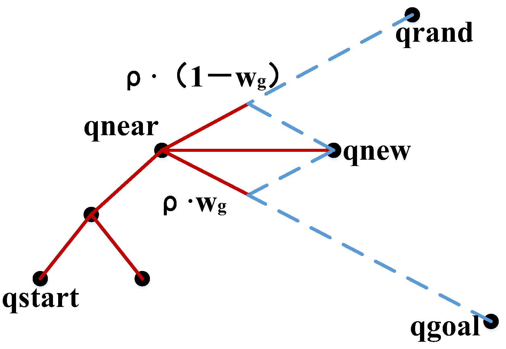
The traditional RRT* path-planning algorithm performs a random search in the state space, so the random sampling points are evenly distributed in the global map, and a huge random tree is generated from the root node through the expansion of new nodes. This not only consumes time but also wastes resources. By improving the traditional RRT* algorithm, a target bias expansion strategy is proposed. It combines random tree expansion with a target bias strategy to negate the blindness of the random tree. It also expands to the specified target point range, allows UAVs to quickly approach the target location, and improves path-planning efficiency. The structure of the target bias extension is shown in Figure 2. The new node q new in the random tree expansion process is unfolded, and it uses the goal-biased expansion method to add q goal goal-directed points to the arbitrary point q rand . The increase in goal-directed points causes the generated new node q new to turn in the direction of the combined force; the two points are q rand and q goal . ρ denotes the larger fixed step size of the expansion, w g represents the direction weight of the target point. The direction weight of q rand is 1 w g , while q rand     q near | q rand     q near | is the unit vector of the direction of the sampling point, and q near is the most recent sampled node; the new node expansion of the traditional RRT* algorithm is shown in Equation (1):
q new ( i ) = q near + F ( i ) = q near + ρ ( 1 w g ) q rand q near | q rand q near | , 0 < 1 w g < 1
Since the traditional RRT* path-planning sampling method is too random to allow a UAV to quickly approach the target point, the target bias extension makes the new node q new search for the target point by introducing the target gravity function w g , q goal     q near | q goal     q near | is a target point direction unit vector. The target gravity function is shown in Equation (2):
G ( i ) = ρ w g q goal q near | q goal q near | , 0 < w g < 1
The new expansion of new node q new is shown in Equation (3):
q new ( i ) = q near + F ( i ) + G ( i ) = q near + ρ ( 1 w g ) q rand q near | q rand q near | + ρ w g q goal q near | q goal q near | , 0 < w g < 1
According to the above formula, it can be gleaned that the TD-RRT* algorithm adopts the target bias expansion strategy, so the path search has a certain direction, the time taken by the traditional RRT* algorithm to traverse the whole map to find the path is shortened, the efficiency of path planning is improved, and the path planning is smoother.

3.2. Dynamic Step Size

The traditional RRT* algorithm has a fixed step size in path planning. Although this algorithm is simple, its ability to plan paths is not good. Different step sizes are used for different environmental scenarios. When the terrain environment is complex and the obstacles within it are close to each other, the dynamic step size is selected for expansion. It ensures the smoothness of the generated path and reduces the probability of collision with obstacles. When the terrain is simple and the obstacles are far away from each other, the algorithm chooses a high step size to expand and speed up the convergence. The dynamic step size is introduced to adjust the step size; it is required for the expansion tree and obstacles in real time, and it also solves the opposition between smoothness and real-time functionality in path planning and improves the efficiency of path planning. In this study, the dynamic step size is determined according to the distance between the extended random tree and the obstacles. The step size generated by the dynamic step size strategy is denoted by ρ f . The corresponding expression is shown in Equation (4):
ρ f = { ρ , x > x s , θ θ max ; k ρ ρ min , 1 k ρ < ρ ρ min
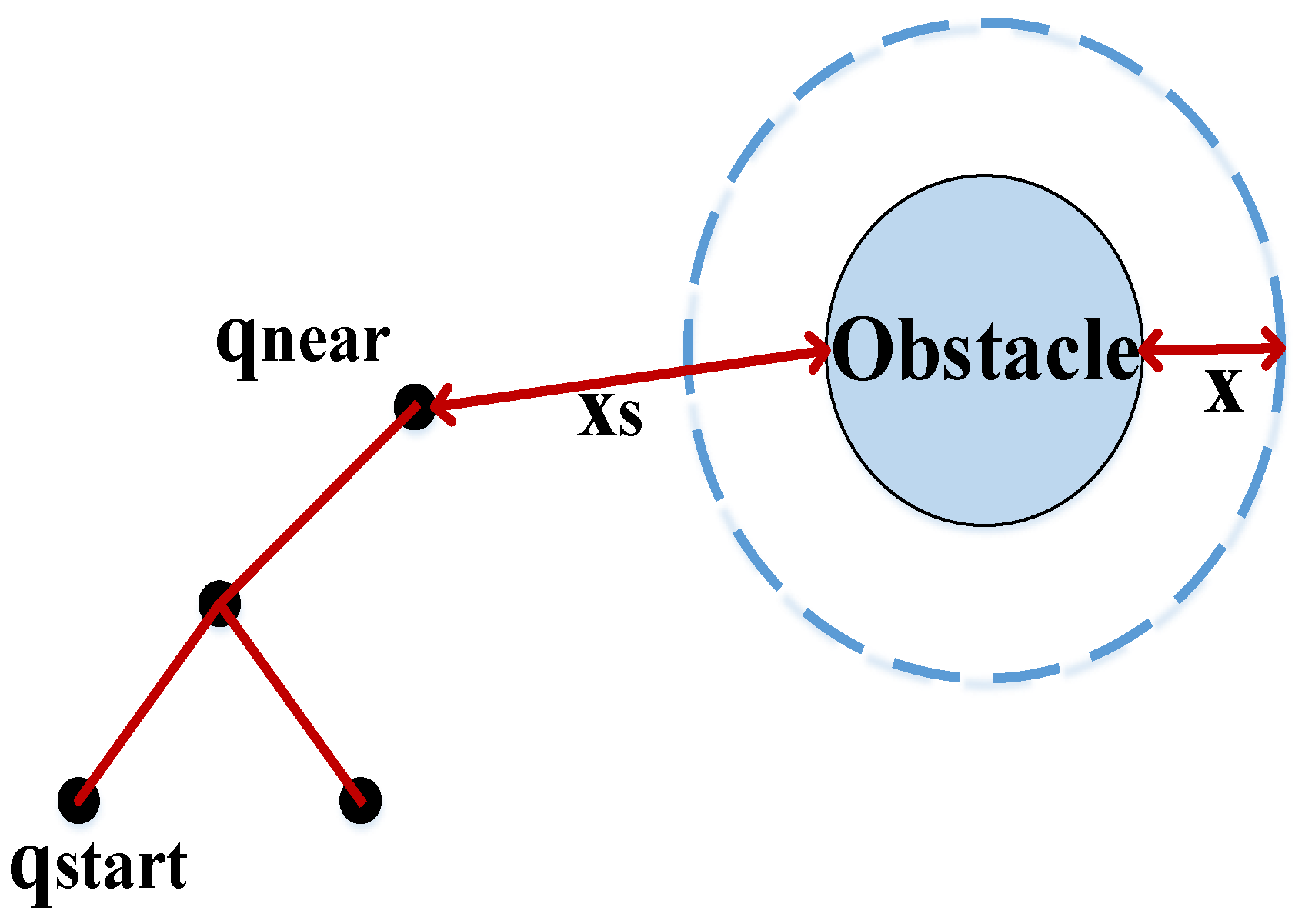
In Equation (4), x represents the set safety value, and x s represents the distance between node q near and the obstacles. As shown in Figure 3, ρ represents the larger fixed step value, k ρ is the minimum step coefficient, and ρ min is the minimum flight step of quad-rotor UAVs. If the step size is selected according to the distance between the obstacles and the node without considering the direction in which the tree is randomly expanding, the search will lead farther and farther away from the target point, thus lowering efficiency. Therefore, this study employs a combination of the target-bias-expanding strategy and the dynamic step size. As shown in Figure 4, θ represents the angle between any directions of random tree expansion and the target direction, and θ max is the preset angle threshold. The threshold θ max for acquisition in this article is 30°. In the process of the random tree expansion, we believe that the process is always offset towards the target point. If the target point and the arbitrary point angle θ are satisfied, i.e., θ θ max , then the algorithm uses a larger fixed step size to improve the efficiency of path planning in the random tree expansion.
The dynamic step size strategy proposed in this paper determines step size according to the distance to the obstacles and the tendency of a rapidly expanding random tree to expand randomly. In the current iteration of path planning, if the distance q near to the obstacles is farther away ( x s > x ) , the random tree expands towards the target area ( θ θ max ) , and ρ f can take a larger fixed step value ρ . Otherwise, the step size of ρ f assumes the value of the dynamic step k ρ ρ min .
The traditional RRT* algorithm environment has insufficient exploration ability and low path search efficiency; sometimes, an effective path cannot be found. In order to solve these problems, the improved algorithm in this paper is applied to obtain q new ; then, it finds the nearest node q near - new of q new in the random tree expansion. Finally, it calculates the path costs of q new and q near - new and draws a circle with a radius of distance; q near - new denotes the center of the circle, where distance ρ . If L cost is less than or equal to distance in the cost function, then the new node q new is not resampled, but q new is added to the random tree expansion, which can reduce the exploration of repeating regions. The cost function is shown in Equation (5):
L cost = distance ( q new , q near new )

3.3. Path-Smoothing Processing

An initial path was obtained by improving the RRT* algorithm. It has many folded paths consisting of two points. There are a large number of inflection points when quad-rotor UAVs are in flight; this will affect the stability of the flight attitude, even resulting in a significant reduction in their work efficiency. Generating this initial path cannot be directly applied to quad-rotor UAV flight. The path needs to be smoothed. There are various ways of smoothing it: the common ways are B-spline curve interpolation [42,43], Quadratic Bessel curve interpolation [44], Quintic polynomial interpolation [45], Cantmull–Rom curve interpolation [46], etc. The B-spline curve interpolation method has the advantage of modifying the local inflection points of the path, and it also has good continuity with respect to solving the above problems efficiently and quickly. We chose to apply the B-spline curve interpolation method to path smoothing.
The B-spline curve expression is shown in Equation (6):
P ( u ) = i = 0 n P i B i , k ( u )
P ( u ) is the curve of each segment, k denotes the curve order of the B-spline, i is the number of iterations, P i denotes the coordinates of the given control point, P i B i , k ( u ) is the basis function, and the expression of P i B i , k ( u ) is shown in Equation (7):
P i B i , k ( u ) = 1 k ! r = 0 k i ( 1 ) r C k + 1 r ( u + k i r ) k , i = 0 , 1 , 2 , , k
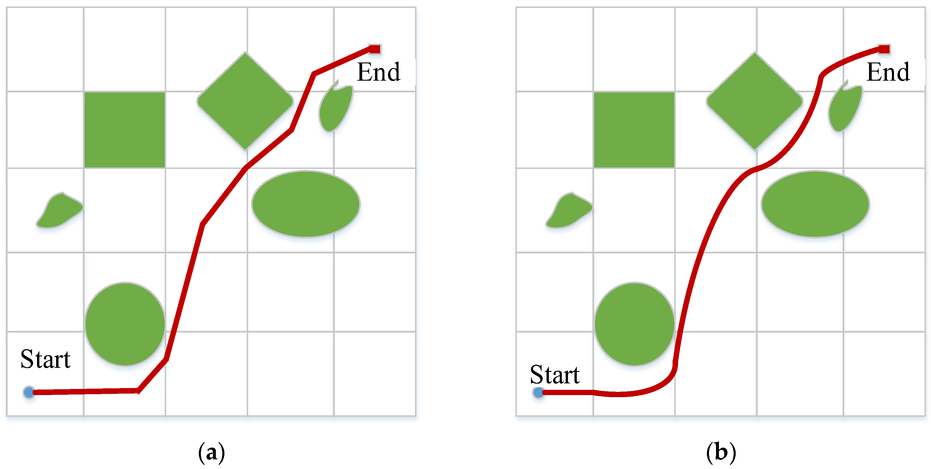
We let k = 3 ; according to the position of the end point and the slope of the tangent line, a smoothed curve was obtained. Figure 5a shows the path before smoothing. Figure 5b shows the path after smoothing.

3.4. Flowchart of the TD-RRT* Algorithm

The implementation steps for the TD-RRT* algorithm discussed in this paper are shown in Figure 6.
Step 1: We search for the quad-rotor UAVs’ path planning nodes and set the parameters, such as the UAV start node q start , the target node q goal , the locations of obstacles, etc.
Step 2: We generate q rand randomly in the flyable area of the quad-rotor UAVs. We use a target bias strategy to find the closest point of the tree node q near to the random node, connecting q near and q rand , for which the direction is q near q rand .
Step 3: We connect q near q rand and q near q goal with an angle of θ between the two path directions. A new node, q new , is identified by introducing the target gravity function.
Step 4: We set the dynamic step size to determine whether there are obstacles between the new nodes q new and q near . If there are no obstacles ( x s > x , θ θ max ), the expansion is executed with a larger fixed step size of ρ . If there are obstacles between the two points, the dynamic step strategy is used for expansion with a dynamic step size of k ρ ρ min , for which the condition is ( 1 k ρ < ρ ρ min );
Step 5: We determine whether node q new is satisfies the collision constraints and cornering constraints. If it does not, we discard q new and jump to step 1 for cyclic execution; if it does satisfy the collision constraints along with the cornering constraints, node q new is retained and added to the random tree.
Step 6: The searched optimal path is smoothed to reduce the path inflection points, shorten the distance, and improve the flight stability of the quad-rotor UAVs. Finally, the UAVs arrive at the target point.

4. Simulation Experiments

4.1. Experimental Environment

In order to verify the superiority of the TD-RRT* algorithm, this experiment is designed to simulate and compare the traditional RRT* algorithm used for path planning with the TD-RRT* algorithm. During the experiment, the quad-rotor UAVs’ size and the bodies of the quad-rotor UAVs are regarded as a prime point. The simulation experiment environment is shown below:
  • Operating System—Windows10 (64 bits);
  • Computer graphics cards—NVIDIA GeForce GTX 1650;
  • Processor (CPU)—Intel (R) Core (TM) i5-10400F CPU @ 2.90 GHz.

4.2. Simulation Experiment

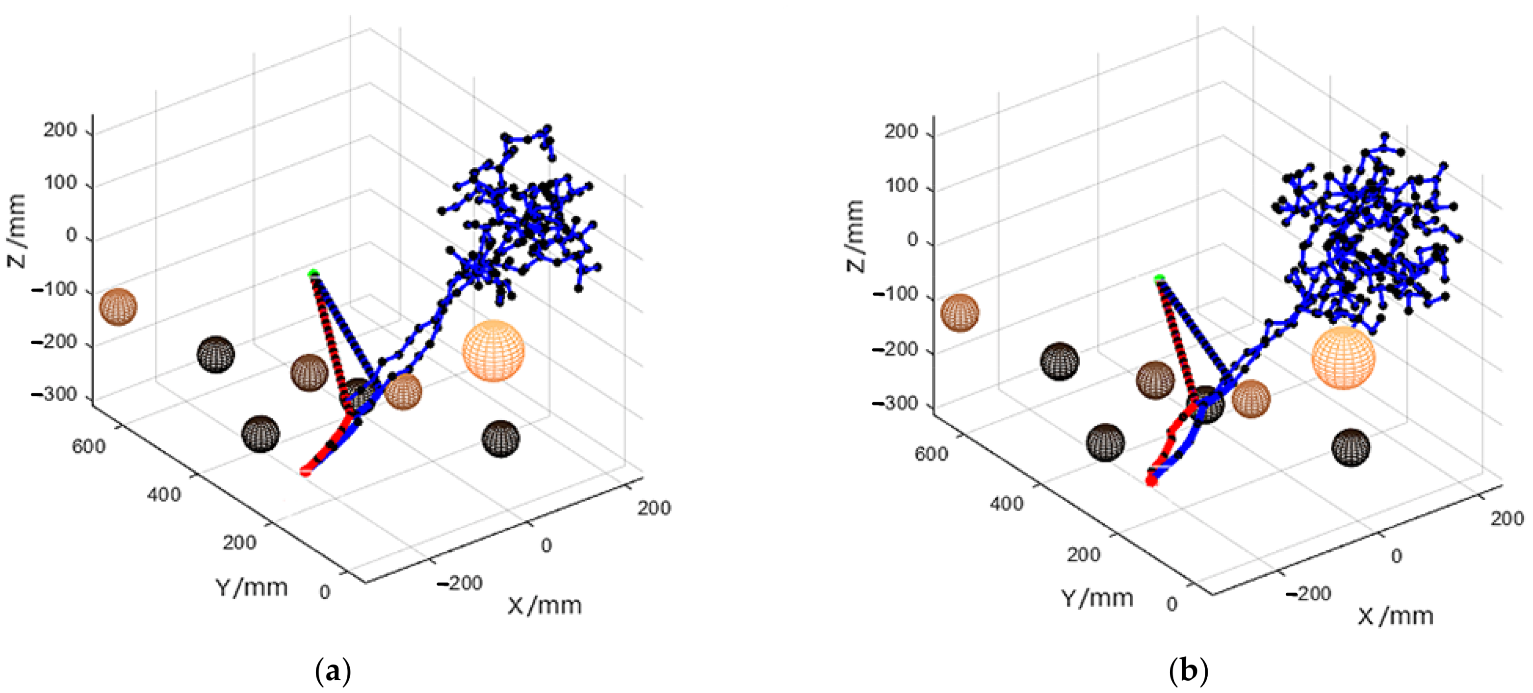
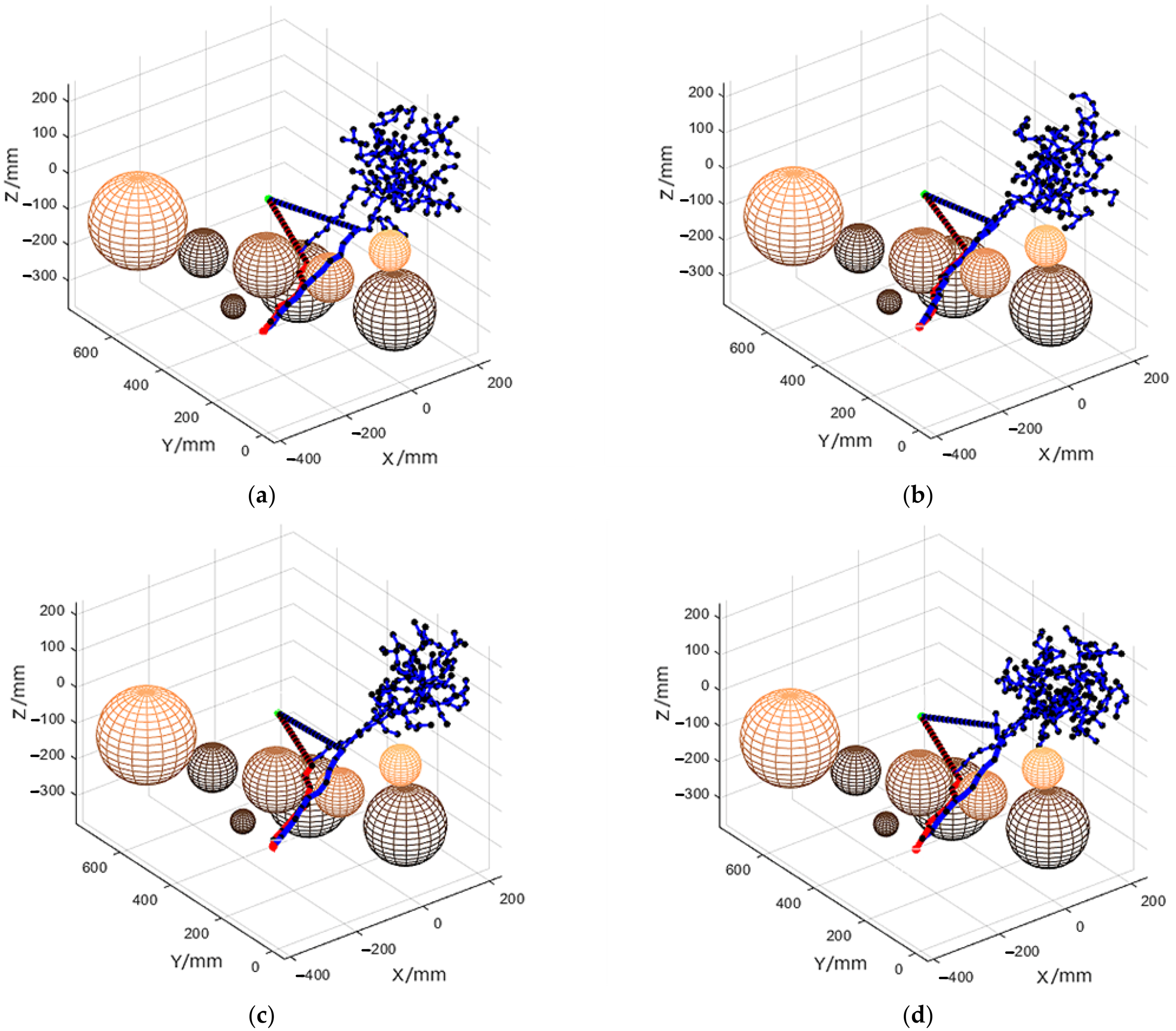
The simulation experiment is divided into 3 parts: the number of iterations, elapsed time for path planning, and the path planning distance between the TD-RRT* algorithm and the traditional RRT* algorithm. The overall environment scales of the quad-rotor UAVs’ path planning are X∈(−200, 200), Y∈(0, 600), and Z∈(−300, 200). The coordinates of the initial point are (−300, 150, −200), and the coordinates of the target point are (100, 600, −200), for which the unit is mm. Because the RRT* algorithm is affected by randomness, it is necessary to conduct multiple sets of experimental validations to compare the performance difference between the TD-RRT* algorithm and the traditional RRT* algorithm in terms of quad-rotor UAV path planning, wherein the UAVs were under the same simulation experimental conditions. A simple environment was simulated with the sphere radius of eight obstacles [15,15,15,15,15,15,15,30] (the unit used here is also mm). The radius of the obstacles is the same as that just mentioned. Figure 7 shows six sets of experiments comparing the traditional RRT* with the TD-RRT* in the simple environment.
In Figure 7a–f, the red solid line represents the optimal path determined by the TD-RRT* algorithm in the simulation experiments. The distance between the dots in blue and the solid line in red represents the dynamic step size in searching for the path. The blue solid line represents the optimal path of the traditional RRT* algorithm in the simulation experiments. The distance between the dots in black and the solid line in blue represents the fixed step size in searching for the path. The blue line in the upper right corner of Figure 7 represents the redundant route of the traditional RRT* algorithm while searching for the target point. The data from the six sets of simulation experiments conducted on simple environment terrain are shown in Table 1.
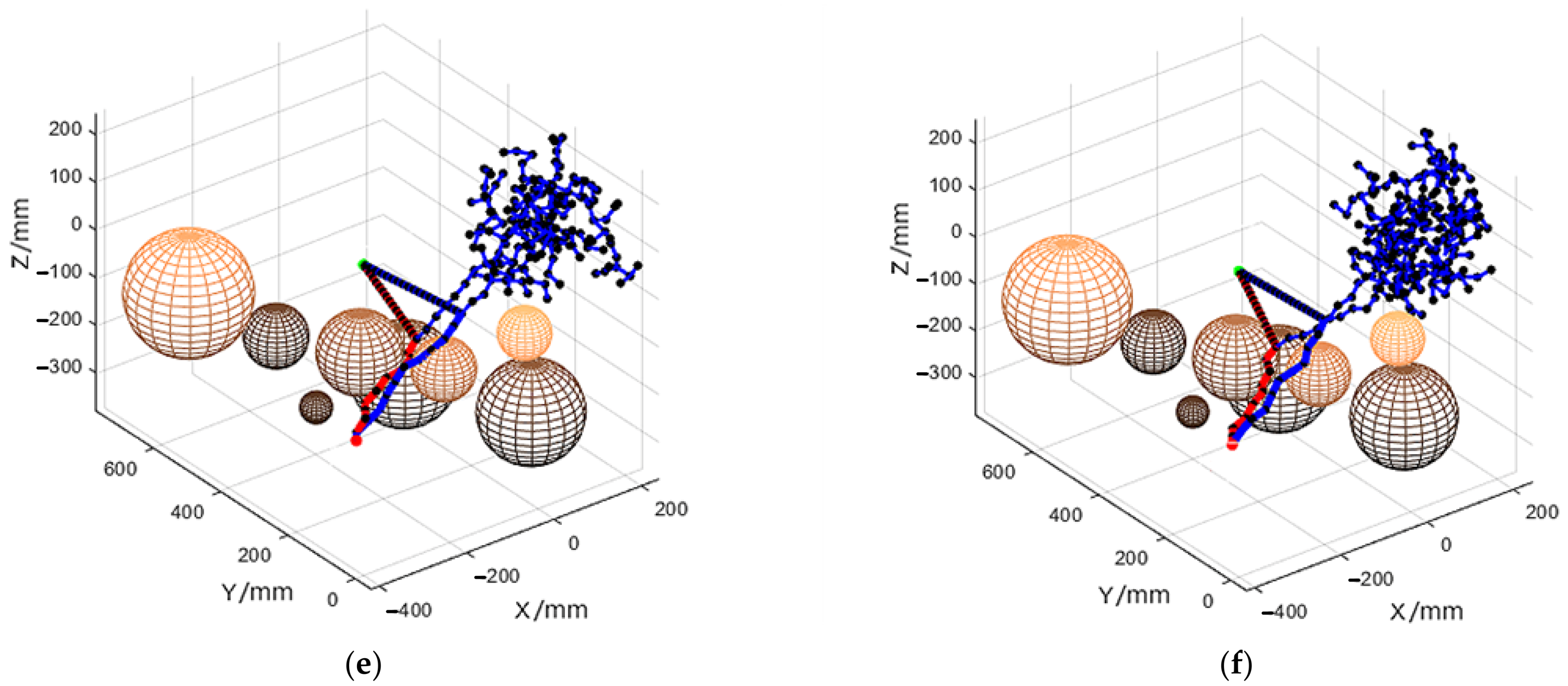
By expanding the diameter of the obstacles to form a complex environmental simulation, the eight resulting obstacle sphere radius are [15, 30, 60, 30, 50, 50, 40, 15]. In the complex environment of the traditional RRT* and TD-RRT* simulation experiments, the same six groups of experiments were also conducted. The details are shown in Figure 8a–f.
The six sets of simulation experimental data for complex environmental terrain are shown in Table 2.

4.3. Path-Planning Efficiency Analysis

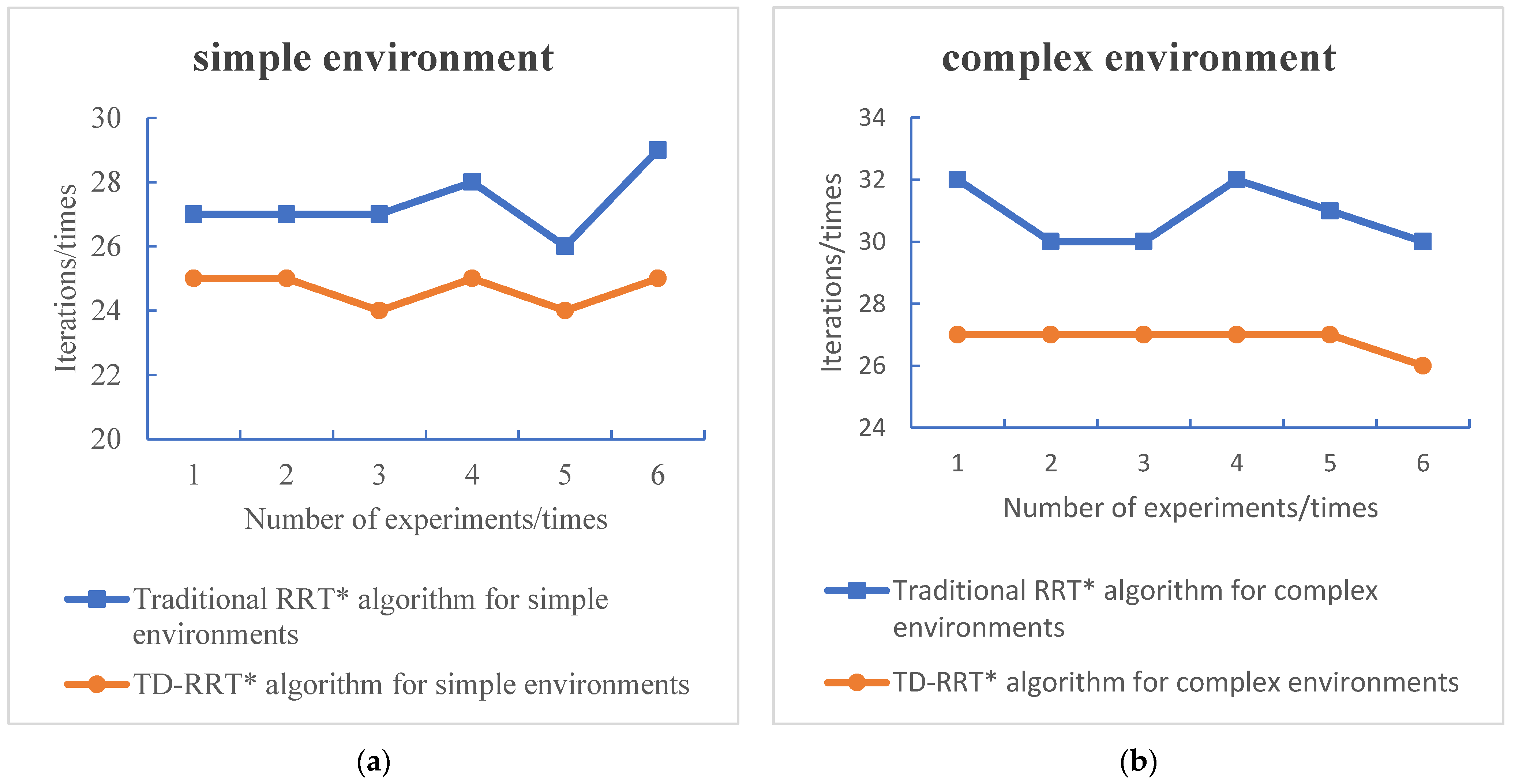
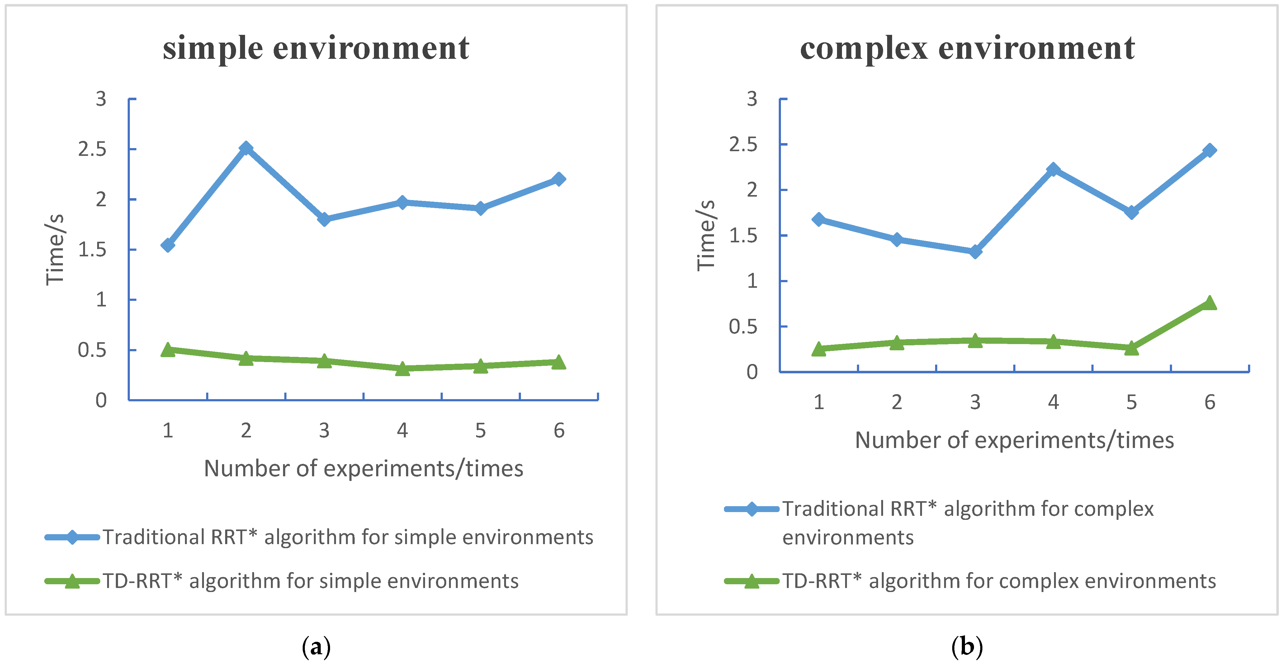
Path-planning efficiency is measured by two factors: the number of iterations and time. If the iteration number is low and the time consumed is short, this indicates that the corresponding path-planning efficiency is higher. Simulated terrain maps of a simple environment and a complex environment were made in six groups of experiments. In the simple environment, the average number of iterations of the traditional RRT * algorithm is 27 (rounded, the same as above), and the average number of iterations of the TD-RRT * algorithm is 25. In the simple environment, the average time consumption of the traditional RRT * algorithm is 1.9892 s, and the average time consumption of the TD-RRT* algorithm is 0.3916 s. In the complex environment, the average number of iterations of the traditional RRT * algorithm is 31, and the average number of iterations of the TD-RRT* algorithm is 27. The average time consumption of the traditional RRT* algorithm in the complex environment is 1.8109 s, and the average time consumption of the TD-RRT* algorithm is 0.3822 s. From the analysis of the iteration number and time data, we can see that the average number of iterations for the TD-RRT* algorithm is two times less than that for the traditional RRT* algorithm for the simple environment, and the amount of time consumed is 1.5976 s shorter, on average. The average value of the number of iterations of the TD-RRT* algorithm in the complex environment is four times less than that for the traditional RRT* algorithm, and the amount of time consumed is 1.4287 s shorter, on average. The number of iterations of the TD-RRT* algorithm and the traditional RRT* algorithm in the simple environment is shown in Figure 9a,b. The amounts of time consumed by the TD-RRT* algorithm and the traditional RRT* algorithm in the complex environment are shown in Figure 10a,b.

4.4. Analysis of Path Optimization Effect

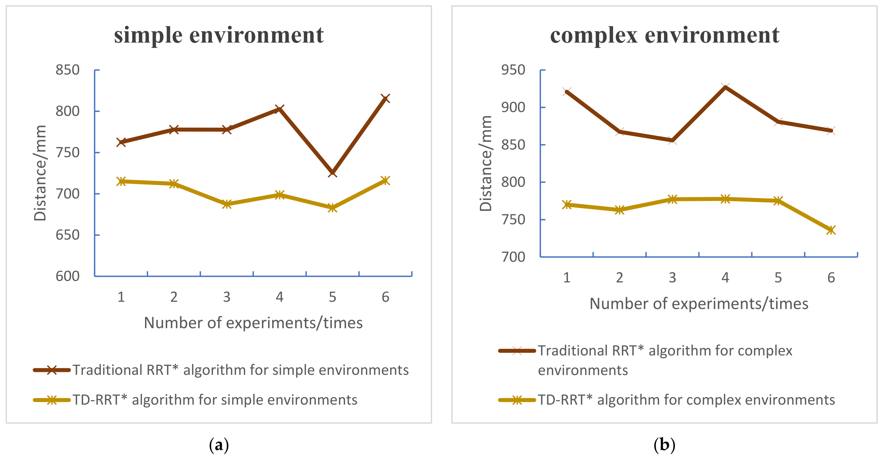
The distance from the initial point to the end point of TD-RRT* algorithm and traditional RRT* algorithm in a complex environment is shown in Figure 11a,b. In the global path-planning process, simulated environmental obstacles need to be detected; if the obstacles’ size is too large and/or the number of obstacles increases, the number of path nodes will increase. The shorter the distance of the path, the better the path-planning effect. From the experimental data, it can be seen that the average value of the distance from the initial point to the end point for the traditional RRT* in the simple environment is 776.9233 mm, the average value of the distance of TD-RRT* in the simple environment is 702.0971 mm, the average value of the distance of the traditional RRT* algorithm in the complex environment is 886.8216 mm, and the average value of the distance of the TD-RRT* algorithm in the complex environment is 766.5199 mm. The average value of the distance of the TD-RRT* algorithm in the simple environment is 74.8262 mm, which is less than the average value of distance traveled for the traditional RRT* algorithm. The average value of distance traveled in complex environments for the TD-RRT* algorithm is 120.3017 mm, which is less than the average value of distance traveled for the traditional RRT* algorithm.

5. Discussion

The path-planning ability of the TD-RRT* algorithm exhibits excellent robustness. It mitigates the problems regarding long durations, long distances, and the large number of iterations challenging the traditional RRT* algorithm. The TD-RRT* algorithm employs a dynamic step size, and it solves the problem of long durations caused by a fixed-step-size search path. A target bias extension was proposed: it solves the problem of a weak orientation toward the target point. Under the same environmental conditions, the efficiency of path planning was considered. Compared with the traditional RRT* algorithm’s path-planning ability, the optimization effect of the TD-RRT* algorithm discussed in this paper is more obvious. For example, in Figure 9 and Figure 10, it is obvious that, both in simple and complex environments, the number of iterations and time consumed by the TD-RRT* algorithm are lower than those for the traditional RRT* algorithm. From Figure 11 or the difference in distance traveled, it can be concluded that the distance traveled by the UAVs when guided by the TD-RRT* algorithm is shorter than for the traditional RRT* algorithm in the same environment.
In contrast with the traditional RRT* algorithm, the TD-RRT* algorithm plans the path dynamically according to the flight path and flight state of quad-rotor UAVs. It overcomes the problems regarding the unstable flight of quad-rotor UAVs at the inflection point and collision with obstacles during flight. It has higher flight accuracy and fewer safety issues. The TD-RRT* algorithm showed excellent robustness in the application scenario. For the navigation system, GPS was combined with other satellite navigation systems to receive a variety of signals. At the same time, this system detects the position of the drone. The IMU requires certain configuration requirements to better complete path planning.
The TSRRT* algorithm looks a lot like the TD-RRT* algorithm. We compared the two of them and optimized the new nodes of random tree expansion through multiple sampling methods, wherein time coordination cost functions were used to improve the efficiency of path planning. The TD-RRT* algorithm proposed in this paper optimizes the new nodes of random tree expansion through the distance cost function. It optimizes the new nodes in the process of random tree expansion by comparing the sizes of dis and ρ. It also adopts the goal bias strategy to cause the new nodes to slowly approach the target point. A dynamic step size was employed to adjust the step size and plan the path reasonably. Both of them can be well optimized for the generation of new nodes, but their cost functions are different. The TSRRT* algorithm uses the time cost function. The TD-RRT* algorithm in this paper uses the distance cost function, and it adds the target bias and dynamic step size strategy. In the later stage, through the study of the two algorithms, we hope that a new algorithm can be obtained, allowing path-planning efficiency to rise to a higher level.
Although the TD-RRT* algorithm has excellent path-planning capabilities, there are still some shortcomings. It is still unclear how the high time consumption in route planning, as well as the fact that obstacles become dynamic during the path-planning process, should be dealt with. In order to solve the problem pertaining to the long consumption time, the path from the initial point to the target point was optimized. The search path was changed from the initial point to the target point and from the target point to the starting point. A meeting is carried out somewhere in the middle so that the path search time can be saved. In the dynamic environment, the real-time obstacle avoidance of the quad-rotor UAVs was achieved by incorporating the artificial potential field method. Later work will further study and improve on this approach.

6. Conclusions

Quad-rotor UAVs carry out path planning. This paper improves on the traditional RRT* algorithm and proposes the TD-RRT* algorithm with target bias expansion and a dynamic step size. Random tree expansion was combined with the target bias strategy to remove the blindness of the random tree, expanding to the specified target point range area to approach the target position quickly. Then, a dynamic step size was introduced to accelerate the search speed; this solves the problems of ineffective expansion in the path generation process and adjusts the step size required for expanding the tree and obstacles in real time, thus addressing the opposition between smoothing and real-time operability in path planning. These features improve the algorithm’s searching efficiency. Finally, three-fold B-spline curve interpolation is used to smooth the path so that the optimal flight path of the quad-rotor UAVs can be determined.
Compared with the traditional RRT* algorithm, the TD-RRT* algorithm has higher path-planning efficiency and generates shorter path-planning travel distances and smoother path lines. Path optimization works better. The TD-RRT* algorithm significantly improves the efficiency of path planning and the planning effect for quad-rotor UAVs.
In this paper, the path planning of quad-rotor UAVs in space in an obstacle-strewn environment is studied. In the future, we will apply the TD-RRT* algorithm for path planning in a practical scenario. We plan to use quad-rotor UAVs for practical flights in a complex environment filled with dynamic obstacles to verify the reliability of the algorithm. At the same time, it is also necessary to consider the problem of environmental perception. The IMU unit at the core position of the quad-rotor UAVs is in place to ensure the normal operation of the device functions and navigation functions.

Author Contributions

Conceptualization, H.G. and X.H.; methodology, H.G. and X.H.; software, J.X.; validation, X.H.; formal analysis, X.H.; investigation, H.G. and X.H.; resources, H.G.; data curation, H.G.; writing—original draft preparation, X.H.; writing—review and editing, X.H., H.G. and B.G.; visualization, H.G. and X.H.; supervision, H.G.; project administration, H.G. All authors have read and agreed to the published version of the manuscript.

Funding

This research was funded by the Anhui Provincial Department of Education’s Natural Science Foundation Major Project, China, grant number 2023AH040275, and Anhui Provincial Department of Education’s Natural Science Foundation Key Projects, China, grant numbers KJ2020A0076 and 2023AH051866.

Data Availability Statement

Data are contained within the article.

Conflicts of Interest

The authors declare no conflict of interest.

References

  1. Lyu, X.M.; Zhou, J.N.; Gu, H.W.; Li, Z.X.; Shen, S.J.; Zhang, F. Disturbance Observer Based Hovering Control of Quadrotor Tail-Sitter VTOL UAV Using Synthesis. IEEE Robot. Autom. Lett. 2018, 14, 2910–2917. [Google Scholar] [CrossRef]
  2. Yunes, A.; Murat, M.; Ayman, K.; Gamal, E. A numerically-stable trajectory generation and optimization algorithm for autonomous quadrotor UAV. Robot. Auton. Syst. 2023, 170, 104532. [Google Scholar]
  3. Liu, Y.Q.; Xu, D.; Cheng, G.; Chen, G. UAV fast trajectory planning method based on improved A~* algorithm. Flight Mech. 2020, 38, 40–46. [Google Scholar]
  4. Diao, Q.F.; Zhang, J.F.; Liu, M.; Yang, J.X. A Disaster Relief UAV Path Planning Based on APF-IRRT* Fusion Algorithm. Drones 2023, 7, 323. [Google Scholar] [CrossRef]
  5. Zhang, Y.; Chen, Z.Q.; Sun, X.H.; Sun, Q.L.; Sun, M.W. Dynamic surface attitude control of quadrotor UAV based on disturbance rejection. J. Jilin Univ. Eng. Ed. 2019, 49, 562–569. [Google Scholar]
  6. Qi, G.Y.; Huang, D.H. Modeling and dynamical analysis of a small-scale unmanned helirotor. Nonlinear Dyn. Int. J. Nonlinear Dyn. Chaos Eng. Syst. 2019, 98, 2131–2145. [Google Scholar]
  7. Zhou, L.H.; Zhang, J.Q.; Dou, J.X.; Wen, B.C. A fuzzy adaptive backstepping control based on mass observer for trajectory tracking of a quadrotor UAV. Int. J. Adapt. Control Signal Process. 2018, 32, 1675–1693. [Google Scholar] [CrossRef]
  8. Sun, W.Z.; Liu, X.C.; Wu, S.; Cai, C.W. Design of fixed-point multi-rotor UAV wireless charging system for border patrol. J. Electr. Mach. Control 2023, in press.
  9. Wei, T.; Long, C. Path planning of mobile robot based on improved genetic algorithm. J. Beihang Univ. 2020, 46, 703–711. [Google Scholar] [CrossRef]
  10. Chen, Q.L.; He, Q.; Zhang, D.M. UAV Path Planning Based on an Improved Chimp Optimization Algorithm. Axioms 2023, 12, 702. [Google Scholar] [CrossRef]
  11. Gong, H.; Ni, C.; Wang, P.; Cheng, N. Smooth path planning method based on Dijkstra algorithm. J. Beihang Univ. 2023, in press.
  12. Sun, H.; Yuan, Y.; Zhang, Q.; Zhang, X.B. Aviation cable path planning method based on improved A~* algorithm. China Mech. Eng. 2023, 34, 1958–1966, 1974. [Google Scholar]
  13. Fransen, K.; van Eekelen, J. Efficient path planning for automated guided vehicles using a* (astar) algorithm incorporating turning costs in search heuristic. Int. J. Prod. Res. 2023, 61, 707–725. [Google Scholar] [CrossRef]
  14. Bai, X.; Jiang, H.; Cui, J.; Lu, K.; Chen, P.; Zhang, M. UAV Path Planning Based on Improved A and DWA Algorithms. Int. J. Aerosp. Eng. 2021, 2021, 4511252. [Google Scholar] [CrossRef]
  15. Xin, P.; Wang, Y.H.; Liu, X.L.; Ma, X.Q.; Xu, D. Optimize and improve the path planning algorithm of RRT and artificial potential field method. Comput. Integr. Manuf. Syst. 2023, 29, 2899–2907. [Google Scholar]
  16. Tamoor, A.K.; Shuai, L.; Seifedine, K.; Yunyoung, N. Control Framework for Trajectory Planning of Soft Manipulator Using Optimized RRT Algorithm. IEEE Access 2020, 8, 171730–171743. [Google Scholar]
  17. Yu, F.J.; Shang, H.Q.; Zhu, Q.L.; Zhang, H.S.; Chen, Y. An efficient RRT-based motion planning algorithm for autonomous underwater vehicles under cylindrical sampling constraints. Auton. Robot. 2023, 47, 281–297. [Google Scholar] [CrossRef]
  18. Huang, G.; Ma, Q. Research on path planning algorithm of autonomous vehicles based on improved RRT algorithm. Int. J. Intell. Transp. Syst. Res. 2022, 20, 170–180. [Google Scholar] [CrossRef]
  19. Li, J.; Liu, H.; Lai, K.K.; Ram, B. Vehicle and UAV Collaborative Delivery Path Optimization Model. Mathematics 2022, 10, 3744. [Google Scholar] [CrossRef]
  20. Zhang, X.; Zhu, T.; Du, L.; Hu, Y.; Liu, H. Local path planning of autonomous vehicle based on an improved heuristic bi-rrt algorithm in dynamic obstacle avoidance environment. Sensors 2022, 22, 7968. [Google Scholar] [CrossRef]
  21. Meng, B.H.; Godage, I.S.; Kanj, I. RRT*-based Path Planning for Continuum Arms. IEEE Robot. Autom. Lett. 2022, 7, 6830–6837. [Google Scholar] [CrossRef] [PubMed]
  22. Guo, Y.; Liu, X.; Jiang, W.; Zhang, W. Collision-Free 4D Dynamic Path Planning for Multiple UAVs Based on Dynamic Priority RRT* and Artificial Potential Field. Drones 2023, 7, 180. [Google Scholar] [CrossRef]
  23. Wan, X.; Ye, Y.; Leitao, Y.; Zhu, L. A global path planning algorithm based on improved RRT*. Control Decis. 2022, 37, 829–838. [Google Scholar]
  24. Li, Y.; Wei, W.; Gao, Y.; Wang, D.; Fan, Z. PQ-RRT*: An improved path planning algorithm for mobile robots. Expert Syst. Appl. 2020, 152, 113425. [Google Scholar] [CrossRef]
  25. Fan, J.; Chen, X.; Liang, X. UAV trajectory planning based on bi-directional APF-RRT* algorithm with goal-biased. Expert Syst. Appl. 2023, 213, 119137. [Google Scholar] [CrossRef]
  26. Nayagam, R.D.; Selvathi, D.; Geeta, R.; Gopinath, D.; Sivakumar, G. Mobile Application based Indoor Positioning and Navigational System using Dijkstra’s Algorithm. J. Phys. Conf. Ser. 2023, 2466, 012007. [Google Scholar] [CrossRef]
  27. Du, Y.W. Multi-UAV Search and Rescue with Enhanced A* Algorithm Path Planning in 3D Environment. Int. J. Aerosp. Eng. 2023, 2023, 8614117. [Google Scholar] [CrossRef]
  28. Melchiorre, M.; Salamina, L.; Scimmi, S.L.; Pastorelli, S. Experiments on the Artificial Potential Field with Local Attractors for Mobile Robot Navigation. Robotics 2023, 12, 81. [Google Scholar] [CrossRef]
  29. Luo, H.; Jiang, T.; Zhou, N.; Xu, L.; Tan, X.M.; Cheng, Y.J. Improved two-stage smooth search algorithm for RRT. Comput. Eng. Appl. 2022, 58, 74–84. [Google Scholar]
  30. Gu, Z.L.; Liu, Y.; Sun, W.B.; Yue, G.; Sun, S.W. UAV dynamic route planning algorithm based on RRT. Comput. Sci. 2023, 50, 65–69. [Google Scholar]
  31. Chen, D.; Diao, X.Y.; Chen, W.; Gao, P.; Ge, L.Q. Online rolling path planning of UAV based on AI-RRT* algorithm. Flight Mech. 2023, 41, 54–60. [Google Scholar]
  32. Yang, X.C.; Du, Y.L.; Bu, Y.N.; Liu, Y.B.; Gao, C. Online three-dimensional RRT~* collaborative route planning based on hierarchical decomposition. Syst. Eng. Electron. Technol. 2023, 45, 1409–1419. [Google Scholar]
  33. Chen, J.T.; Li, H.Y.; Ren, H.R.; Lu, R.Q. Indoor collaborative path planning of high-rise firefighting UAV based on RRT forest algorithm. Acta Autom. Sin. 2021, 45, 1–12. [Google Scholar]
  34. Wang, F.B.; Gao, Y.F.; Chen, Z.; Gong, X.; Zhu, D.R.; Cong, W.L. A Path Planning Algorithm of Inspection Robots for Solar Power Plants Based on Improved RRT*. Electronics 2023, 12, 4455. [Google Scholar] [CrossRef]
  35. Long, H.Y.; Li, G.; Zhou, F.L.; Chen, T.F. Cooperative Dynamic Motion Planning for Dual Manipulator Arms Based on RRT*Smart-AD Algorithm. Sensors 2023, 23, 7759. [Google Scholar] [CrossRef] [PubMed]
  36. Zhang, Y.; Gao, F.; Zhao, F.K. Research on Path Planning and Tracking Control of Autonomous Vehicles Based on Improved RRT* and PSO-LQR. Processes 2023, 11, 1841. [Google Scholar] [CrossRef]
  37. Fan, J.M.; Chen, X.; Wang, Y.; Chen, X.M. UAV trajectory planning in cluttered environments based on PF-RRT* algorithm with goal-biased strategy. Eng. Appl. Artif. Intell. 2022, 114, 105182. [Google Scholar] [CrossRef]
  38. Liao, B.; Wan, F.Y.; Hua, Y.; Ma, R.R.; Zhu, S.R.; Qing, X.L. F-RRT*: An improved path planning algorithm with improved initial solution and convergence rate. Expert Syst. Appl. 2021, 184, 115457. [Google Scholar] [CrossRef]
  39. Guo, Y.C.; Liu, X.X.; Jiang, W.; Zhang, W.G. HDP-TSRRT*: A Time-Space Cooperative Path Planning Algorithm for Multiple UAVs. Drones 2023, 7, 170. [Google Scholar] [CrossRef]
  40. Zhang, W.M.; Fu, Z.X. Path Planning of Mobile Robot Based on Improved RRT~* Algorithm. J. Huazhong Univ. Sci. Technol. Nat. Sci. Ed. 2021, 49, 31–36. [Google Scholar]
  41. Yi, H.W. Three-dimensional operation path planning of manipulator based on improved ant colony algorithm. Comput. Appl. Softw. 2014, 31, 302–304+307. [Google Scholar]
  42. Cengiz, B.; Sitki, O.; Melih, K.; Ismet, K. Dynamic Centripetal Parameterization Method for B-Spline Curve Interpolation. IEEE Access 2020, 8, 589–598. [Google Scholar]
  43. Chiaravalli, D.; Califano, F.; Biagiotti, L.; De, D.G. Physical-consistent behavior embodied in B-spline curves for robot path planning. IFAC Pap. 2018, 51, 306–311. [Google Scholar] [CrossRef]
  44. Zhou, D. Parametric path generation method for agricultural machinery harvesting operation. Agric. Eng. 2022, 12, 13–21. [Google Scholar]
  45. Xu, J.; Ren, C.F.; Zhang, X.N. Robot Time-Optimal Trajectory Planning Based on Quintic Polynomial Interpolation and Improved Harris Hawks Algorithm. Axioms 2023, 12, 245. [Google Scholar] [CrossRef]
  46. Wang, H.F.; Zhang, Y.; Zhu, Y.K.; Chen, X.B. Path Planning Algorithm for Mobile Robot Based on Improved Bidirectional RRT~*. J. Northeast. Univ. Nat. Sci. Ed. 2021, 42, 1065–1070, 1142. [Google Scholar]
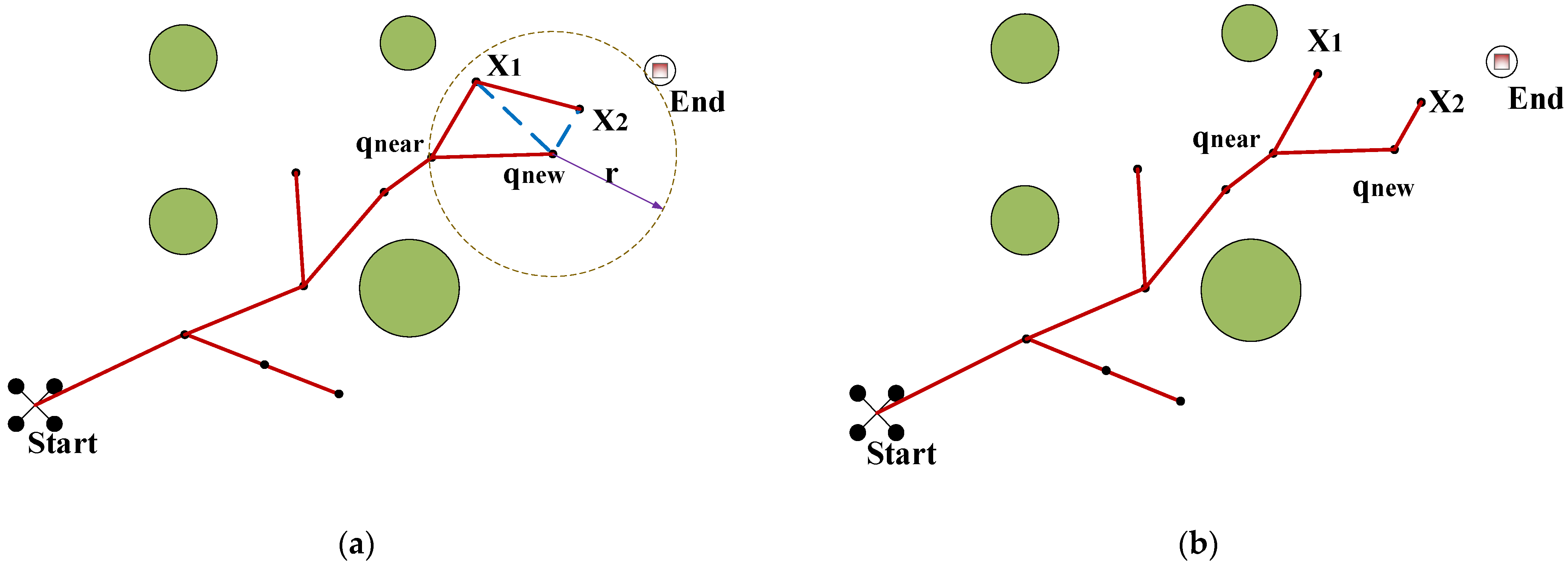
Figure 1. Schematic of RRT* algorithm path asymptotic optimization: (a) schematic diagram of RRT algorithm path-planning process; (b) schematic of RRT* algorithm after asymptotic optimization.
Wevj 15 00029 g001
Figure 2. Structure of the target bias extension.
Wevj 15 00029 g002
Figure 3. Distance from obstacles.
Wevj 15 00029 g003
Figure 4. Angle between any point of the extended tree and the target point1.
Wevj 15 00029 g004
Figure 5. Schematic diagram of path-smoothing process: (a) path before smoothing; (b) smoothed path.
Wevj 15 00029 g005
Figure 6. TD-RRT* path-planning flowchart.
Wevj 15 00029 g006
Figure 7. Simple environment path-planning results. (a) Path planning experiment results 1. (b) Path planning experiment results 2. (c) Path planning experiment results 3. (d) Path planning experiment results 4. (e) Path planning experiment results 5. (f) Path planning experiment results 6.
Wevj 15 00029 g007aWevj 15 00029 g007b
Figure 8. Complex environment path planning results. (a) Path planning experiment results 1. (b) Path planning experiment results 2. (c) Path planning experiment results 3. (d) Path planning experiment results 4. (e) Path planning experiment results 5. (f) Path planning experiment results 6.
Wevj 15 00029 g008aWevj 15 00029 g008b
Figure 9. Schematic comparison of the number of iterations. (a) Comparison of the number of iterations of the two algorithms in a simple environment. (b) Comparison of the number of iterations of the two algorithms in a complex environment.
Wevj 15 00029 g009
Figure 10. Schematic diagram of time consumption comparison. (a) Comparison of the time consumption of the two algorithms in a simple environment. (b) Comparison of the time consumption of the two algorithms in a complex environment.
Wevj 15 00029 g010
Figure 11. Schematic comparison of routes. (a) Comparison of the distance between the two algorithms in a simple environment. (b) Comparison of the distance between the two algorithms in a complex environment.
Wevj 15 00029 g011
Table 1. Simulation data for simple environment path planning.
EnvironmentsNumber of Experimental GroupsAlgorithmsTravel Distance/mmNumber of IterationsTiming/s
Simple environmentGroup 1Traditional RRT* algorithm762.4299271.5437
TD-RRT* algorithm715.1080250.5055
Group 2Traditional RRT* algorithm777.7699272.5113
TD-RRT* algorithm712.1347250.4176
Group 3Traditional RRT* algorithm777.7230271.7996
TD-RRT* algorithm687.4352240.3927
Group 4Traditional RRT* algorithm802.5991281.9696
TD-RRT* algorithm698.6941250.3158
Group 5Traditional RRT* algorithm725.4604261.9095
TD-RRT* algorithm683.1005240.3412
Group 6Traditional RRT* algorithm815.5573292.2013
TD-RRT* algorithm716.1098250.3815
Table 2. Complex environment path planning simulation data.
EnvironmentsNumber of Experimental GroupsAlgorithmsTravel Distance/mmNumber of IterationsTiming/s
Complex environmentGroup 1Traditional RRT* algorithm920.8943321.6757
TD-RRT* algorithm770.0329270.2548
Group 2Traditional RRT* algorithm867.4032301.4547
TD-RRT* algorithm762.9468270.3240
Group 3Traditional RRT* algorithm855.9435301.3218
TD-RRT* algorithm777.2276270.3476
Group 4Traditional RRT* algorithm926.9955322.2267
TD-RRT* algorithm777.6863270.3358
Group 5Traditional RRT* algorithm880.7327311.7511
TD-RRT* algorithm775.1276270.2661
Group 6Traditional RRT* algorithm868.9602302.4354
TD-RRT* algorithm736.0981260.7648
Disclaimer/Publisher’s Note: The statements, opinions and data contained in all publications are solely those of the individual author(s) and contributor(s) and not of MDPI and/or the editor(s). MDPI and/or the editor(s) disclaim responsibility for any injury to people or property resulting from any ideas, methods, instructions or products referred to in the content.