Review

Degradation Mechanism and Online Electrical Monitoring Techniques of Stator Winding Insulation in Inverter-Fed Machines: A Review

Institute of Rail Transit, Tongji University, Shanghai 201804, China
*
Author to whom correspondence should be addressed.
World Electr. Veh. J. 2024, 15(10), 444; https://doi.org/10.3390/wevj15100444
Submission received: 17 August 2024 / Revised: 11 September 2024 / Accepted: 26 September 2024 / Published: 29 September 2024
(This article belongs to the Topic Advanced Electric Vehicle Technology, 2nd Volume)

Abstract

:
Inverter-fed machines are widely used in electric vehicle drive systems and have shown a trend toward high voltage and frequency in recent years. They are subjected to multiple types of stress during operation, causing potential short-circuit fault damage to the stator winding insulation. Online condition monitoring of the insulation before or in the early stage of the short circuit fault can effectively reduce maintenance costs and ensure its health. This paper reviews and summarizes the deterioration mechanism and the recent online electrical monitoring techniques. First, four types of failure stress and each type’s failure factors and mechanisms are analyzed. The coupling effect and overall process of multi-physical fields on stator insulation failure are considered. Secondly, the latest online electrical monitoring technologies are summarized. Each technique’s principles, methods, advantages, and disadvantages are analyzed. Finally, existing problems and possible directions for improvement in current research are discussed, focusing on their feasibility and accuracy in practical applications.

1. Introduction

Currently, alternating current (AC) motors are extensively utilized in production, transportation systems, and new energy generation, playing an increasingly vital role due to their electromechanical energy conversion capabilities. Particularly with the continuous development of new energy-storage technologies and rapid charging technologies, coupled with the increasing demands for vehicle performance, high-frequency, high-voltage inverter motors have become a critical component of electric vehicle drive systems and have seen widespread adoption. However, this means an increasing frequency of failures as the application expands and the usage scenarios multiply. Common fault types in AC motors include stator faults, bearing faults, and rotor faults [1], shown as Figure 1. Related research indicates that 30% to 40% of AC motor failures are related to the stator winding [2], with faults in inter-turn insulation, phase-to-phase insulation, and primary insulation, leading to various short-circuit phenomena. Insulation failures generally develop from inter-turn short circuits. When inter-turn insulation degrades, circulating currents occur within the shorted coils. This generates significant heat that further damages the phase-to-phase and groundwall insulation. It ultimately progresses to phase-to-phase and phase-to-ground short-circuits, resulting in irreversible and severe consequences [3]. The progression from initial insulation failure to severe damage typically takes 20 to 60 s in small motors [4] and even less time in larger motors. Therefore, stator insulation issues have garnered considerable attention in motor design, manufacturing, control, and operation.
During motor operation, the stator insulation is subjected to various aging effects, including electrical, thermal, and mechanical aging [5]. Particularly with the widespread adoption of pulse-width modulation (PWM) technology and high-frequency operation, the stator insulation system is subjected to higher voltage stress rates, accelerating insulation aging. High-power motors increase the voltage and current levels in the stator windings, with transient high voltage and current thermal effects further accelerating stator insulation degradation. Additionally, heavy loads and inherent structural asymmetries exacerbate AC motor vibrations, creating mechanical stress contributing to aging stator insulation.
Numerous studies have focused on fault-detection algorithms for stator short circuits, employing methods based on observers [6,7,8], signal processing [9,10,11], and data-driven approaches [12,13,14]. However, monitoring the stator winding condition online before a fault occurs or in its early development stages can further reduce maintenance costs and ensure the safe operation of the motor. In recent years, the online monitoring of stator insulation has become a prominent research area, yielding many valuable findings. This paper addresses the issue of the online monitoring of stator insulation in inverter-driven motors, with the main contents as follows:
(1)
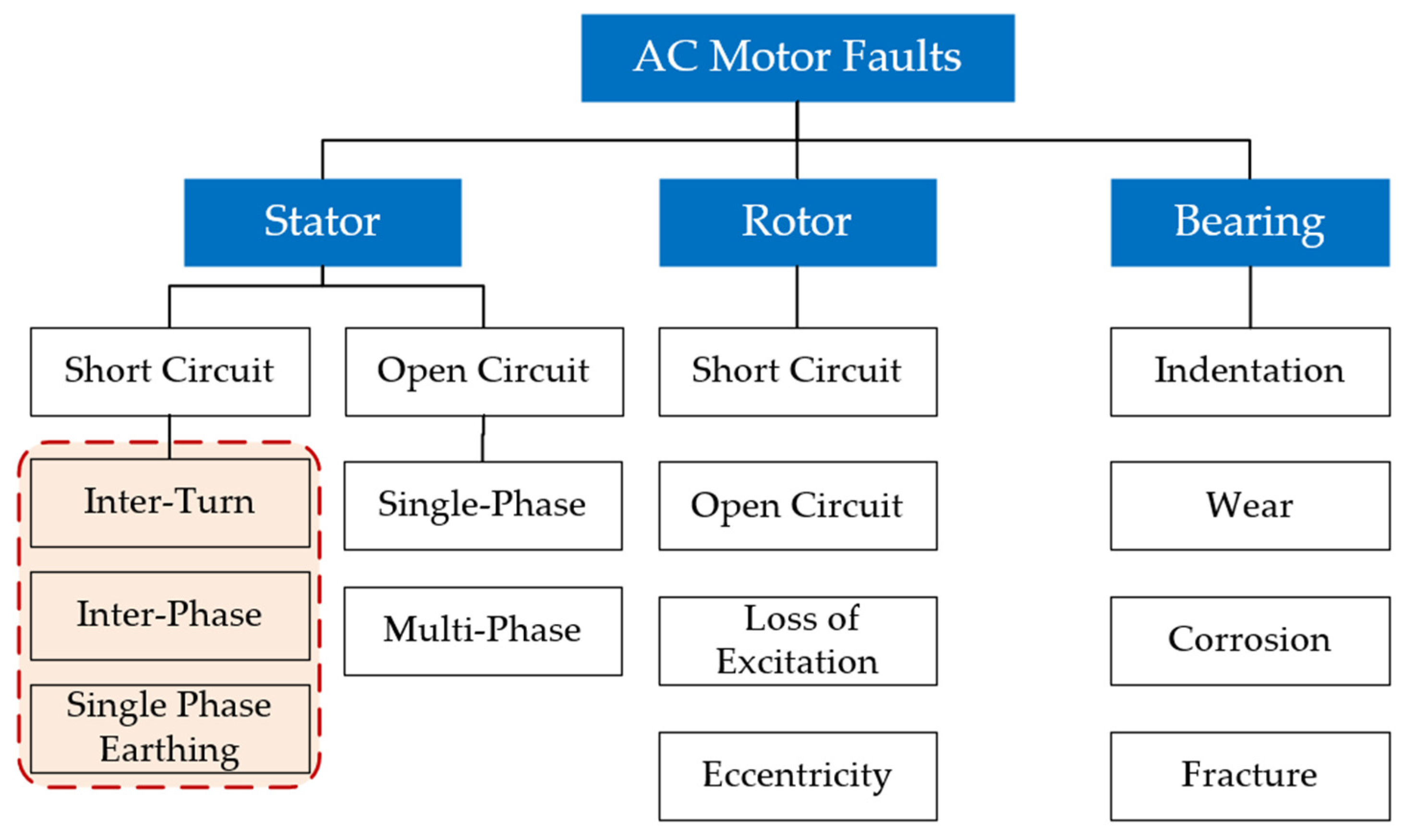
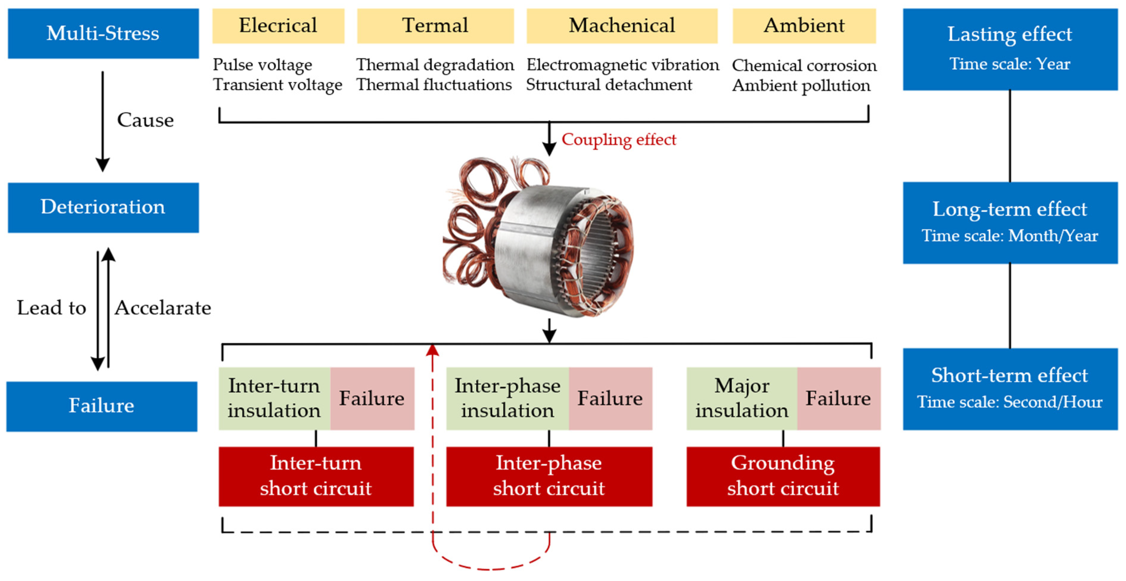
An analysis of four types of stress leading to stator winding insulation failure in AC motors, including the failure mechanisms associated with each stress. The study also summarizes the coupling effects of multiphysics fields on stator insulation failure and the overall process from insulation degradation to failure.
(2)
A comprehensive review of online monitoring methods for stator insulation conditions developed in recent years. We classify these methods into four categories. The latest research is reviewed and summarized for each online monitoring method, including monitoring principles, techniques, advantages, and limitations. The main contributions and shortcomings of each study are discussed.
(3)
In the conclusion and discussion section, this paper provides a summary and further discusses unresolved issues and potential improvements in current research. Particular attention is given to the feasibility and accuracy of these methods in practical applications.

2. Insulation Degradation Mechanism under Multi-Physics Field

Existing research indicates that the primary causes of stator insulation failures can be categorized into four types of stress: electrical stress, thermal stress, mechanical stress, and ambient stress (collectively referred to as TEAM stresses) [15]. In other words, the degradation of stator insulation is a complex process resulting from the combined effects of multiple physical fields, including electrical, thermal, magnetic, and mechanical forces. The IEEE 275 standard provides a multi-factor cyclic aging test model [16], as shown in Figure 2. The factors contributing to the degradation of stator winding insulation are summarized in Table 1, which will be explained in detail in Section 2.1, Section 2.2, Section 2.3 and Section 2.4.

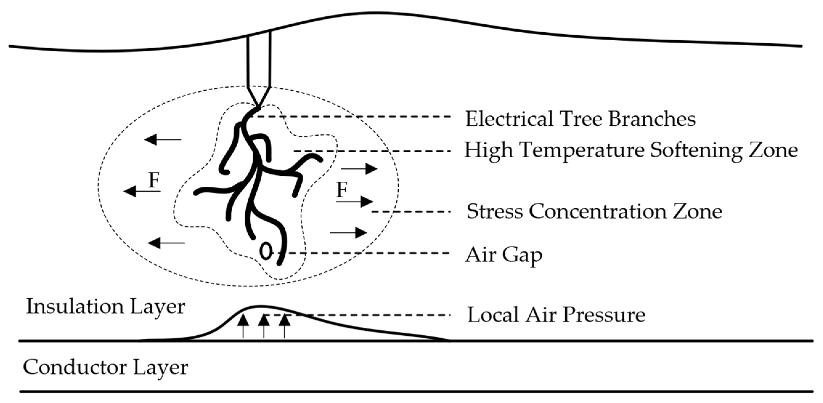
2.1. Electrical Stress

Under the influence of an electric field, the phenomenon of insulation aging caused by partial discharges is called electrical aging. Partial discharge is one of the primary causes of breakdown in the insulation of high-voltage motor stator windings. Most insulation failures are ultimately triggered by the effects of partial discharge in the winding insulation. This refers to discharges occurring in localized regions of the insulator that do not yet result in complete system breakdown but can lead to the formation and propagation of electrical trees within the material and increased leakage currents within the insulation material [17]. Figure 3 shows the growth of the electrical tree in the wire insulation layer. Under the influence of external electrical stress F, heat accelerates insulation degradation and forms a high-temperature softening zone. High-temperature softening accelerates the formation and development of the electrical tree, further expanding it with the action of F. The causes of insulation discharge in stator windings include, but are not limited to, failures in the slot semiconductive layer, slot/end semiconductive layer overlap faults, transient voltage surges, poor electrical contact, and the cumulative effects of inverter pulse voltage [18]. The primary causes of deterioration are associated with the high-frequency pulses of inverters and potential transient voltages.
Cumulative Effect of High-Frequency Pulses. For inverter-driven variable frequency motors, particularly those represented by permanent magnet synchronous motors (PMSMs), the cumulative effect of high-frequency pulses generated at the output of a PWM-type inverter on the turn-to-turn insulation layer of the motor stator windings is a critical factor in insulation deterioration [19]. For instance, in PMSMs, the inter-turn insulation materials of stator windings typically consist of organic materials, such as polyimide, polyester, or epoxy resin. During the manufacturing of motor stators, defects or sharp points are inevitably present in the air gaps between the windings and the insulation medium. When applying repetitive pulse voltages to these windings, the electric fields in these defects, sharp points, and air gaps become highly intense, leading to the initiation and growth of electrical trees at the localized electric field concentrations in the groundwall insulation or inter-turn insulation of the motor windings [20]. Generally, the amplitude, frequency, polarity, and rise time of the impulse voltage are the main factors influencing the cumulative failure characteristics of the dielectric. High-amplitude, high-frequency, bipolar, and short-rise-time pulses have a more severe impact on the life expectancy of winding insulation. The square waves produced by the PWM-type inverters commonly used in PMSMs are characterized by short rise/fall times (with IGBT switching times typically ranging from 50 ns to several microseconds), a high frequency and amplitude, and a bipolar power supply. Such repetitive impulse voltages are the primary cause of accelerated insulation deterioration in inverter-driven motor windings [21]. Additionally, when high slew-rate impulse voltages are applied to the winding insulation, the voltage distribution across the windings becomes highly uneven, resulting in the maximum electric field strength at the inter-turn insulation of the winding ends, where insulation degradation is typically more severe [22].
Transient Voltages. Besides the cumulative effect of high-frequency pulses, potential short-duration voltage surges (transient voltages) also constitute critical electrical stress that can lead to insulation degradation or failure. Suppose the transient voltage surges exceed the dielectric strength of the PMSM stator winding insulation. In that case, they can induce inter-turn insulation discharge and the formation of electrical trees in the insulation material, ultimately resulting in insulation breakdown [23].

2.2. Thermal Stress

Under the influence of thermal fields, the degradation of insulation caused by elevated winding temperatures is referred to as thermal aging. Generally, thermal stress in motors originates primarily from heat generated by losses in the copper conductors, eddy current losses, stray load losses, and core losses [24]. The main contributors are copper losses due to current flow in the winding conductors and magnetic losses in the stator core caused by magnetic flux. Throughout the entire lifecycle of a permanent magnet synchronous motor (PMSM), thermal stress leads to insulation damage primarily through the promotion of oxidation, hydrolysis, and other chemical reactions, as well as through thermal expansion and contraction, which causes physical deformation. The corresponding mechanisms of insulation failure can be categorized into thermal degradation and thermal cycling.
Thermal Degradation. Thermal degradation is the primary mode of deterioration caused by thermal stress, fundamentally an oxidation reaction. At elevated temperatures, the chemical bonds within the organic components of the insulation layer break due to thermally induced vibrations. Once the chemical bonds break, oxygen atoms adsorb onto the broken bonds, shortening and embrittling the polymer chains. This decreases the mechanical strength and viscosity of the insulation, leading to delamination of the inter-turn insulation, which further reduces the insulation’s thermal conductivity and accelerates thermal degradation, ultimately causing insulation breakdown [25]. Faults are generally caused by operational issues, such as overload, phase imbalance, and cooling system failures, as well as design and manufacturing defects, like excessive circulating currents between strands, large strand cross-sections, inter-strand short circuits, and insufficient ventilation. Related studies [26] have conducted finite element simulations of the thermal field under stator insulation degradation and fault conditions. The simulation results indicate that after a fault occurs, the motor’s hottest spot shifts from the rotor to the faulty slot winding, with the maximum thermal stress appearing at the winding ends.
Thermal Cycling. This generally occurs when the motor transitions from no-load to full-load, causing a rapid rise in the temperature of the copper conductors, leading to axial expansion. However, due to the higher thermal expansion coefficient of copper conductors and the lag in the heat conduction of insulation materials, axial shear stress develops between the inter-turn insulation and the copper conductors. Frequent thermal cycling results in fatigue of the bond between the inter-turn insulation and the conductor, ultimately leading to insulation peeling and degradation, followed by delamination between the conductor and insulation [27]. Subsequently, the relative movement between the conductor and insulation further exacerbates insulation wear while inhibiting the heat dissipation process of the copper conductors, eventually leading to insulation breakdown. Thermal cycling faults are usually caused by excessively rapid or frequent load adjustments.

2.3. Mechanical Stress

The process of insulation aging caused by mechanical stress, including electrodynamic forces, electromagnetic forces, and thermal expansion and contraction, is referred to as mechanical aging. The primary mechanisms by which mechanical stress damages insulation include slot bar looseness and end-winding vibrations.
Stator Winding Looseness: The electromagnetic force exerted on stator windings during operation is proportional to the square of the stator current [28]. Consequently, as the load increases, the stator current rises, leading to a rapid increase in the electromagnetic force on the bars, and the stator current harmonics cause additional vibrations in the stator windings [29]. If the slot wedges are securely fastened, the impact of the electromagnetic force is minimal. However, when the slot wedges are inadequately secured, they may vibrate under electromagnetic force, causing friction between the windings, leading to inter-turn insulation wear. This phenomenon exists not only in motors but also in generators. For example, the friction between the bars and the laminated core surfaces can also cause wear on the slot corona protection layer and the main insulation. Modern epoxy-mica insulation, which has a lower thermal expansion coefficient than older thermoplastic insulation materials, such as asphalt-mica, makes this phenomenon more prevalent, posing a rapidly growing cause of insulation aging [30].
End-Winding Vibration: During operation, the electromagnetic forces generated by the magnetic fields of the stator and rotor subject the stator windings, including the slot, slot opening, and end-winding regions, to continuous mechanical vibrations. Suppose the end-winding wedges or binding tapes become loose. In that case, the significant electromagnetic forces can cause the end-windings to collide, leading to abrasion and deformation, resulting in inter-turn insulation degradation. If the slot windings are also loose, relative movement between the windings and the core occurs, with the powerful electromagnetic forces abrading the surface of the main insulation and its semiconductive layer, potentially causing electrical “slot discharges” [31]. Moreover, when the end-windings vibrate, they pivot around the slot opening, and over time, this can cause fatigue fractures in the conductor strands, leading to strand breakage and other fault modes. Some studies [32] have used finite element analysis to examine the mechanical stress intensity on the end-windings and the damage to insulation caused by electromagnetic forces in AC machines. The results indicate significant stress concentration at the coil end-windings, with initial cracks more likely to propagate at this location. Reducing the electromagnetic force can prevent further crack propagation.

2.4. Ambient Stress

Insulation aging caused by ambient factors is termed ambient aging. These factors include but are not limited to, moisture condensation on the windings, oil contamination from bearing leaks, chemical corrosion, excessive humidity, and dirt ingress from the environment into the motor [33]. Although these factors alone may not directly cause insulation aging, they can promote it when combined with other factors. For instance, moisture combined with oil and conductive contaminants can form a conductive contamination layer, leading to surface currents and creeping discharges under an electric field. The combination of oil, moisture, and contaminants can create a sludge that blocks stator ventilation ducts, accelerating the temperature rise of the windings and increasing thermal aging. The ozone generated during partial discharges can also degrade insulation, reducing mechanical strength. Ambient stress affects stator insulation through several fault mechanisms:
Contamination. During motor and train operation, end-windings accumulate dust, oil, water vapor, and carbon powder. If not cleaned promptly due to inadequate maintenance, this can form conductive contamination, leading to surface creeping discharges or even phase-to-phase discharges [34]. When a potential difference exists between the ends of the contamination, such as between blocks on different phase bars, a current may flow through the contamination under the influence of high voltage coupled to the bar surfaces. The high resistance areas within the contamination, such as dry bands, will be subjected to high voltages, potentially causing air breakdown and discharges. This process can carbonize the contamination and the underlying organic insulation material, thereby damaging the insulation [35]. Subsequently, the carbonized area becomes more conductive, transferring voltage stress to other high-resistance areas. This leads to creeping discharges along the insulation surface and eventually forming conductive paths between phase bars, resulting in phase-to-phase discharges.
Moisture. Rain, snow, and poor equipment sealing can cause water to leak towards the end-windings, leading to creeping or even phase-to-phase discharges. Water leakage can damage insulation in two ways. First, it can penetrate the inter-turn or main insulation, causing delamination and reducing its dielectric strength. Second, it can decrease the mechanical strength of the insulation after delamination, thereby increasing the risk of insulation breakdown and fatigue fractures in the windings [36].
Abrasion. In train traction systems, motors must employ axle control methods to ensure high efficiency. During operation, dust, oil, gravel, and other debris from the long and varied railway environment can enter the motor stator, following the motion of the wheels. If not monitored or cleaned regularly, this can cause frictional damage to the inter-turn insulation, particularly in exposed areas of the stator windings, such as the end-windings, increasing the risk of potential insulation damage and inter-turn short-circuit faults [37].

2.5. Interrelationships of Stresses

Various stresses and corresponding monitoring methods for the deterioration of AC motor stator winding insulation have been discussed in Section 2.1, Section 2.2, Section 2.3 and Section 2.4. In reality, the deterioration process of inter-turn insulation results from the coupling effect of multiple fields, including electrical, thermal, magnetic, mechanical, etc. That is, more than one stress or inducement leads to insulation degradation and further leads to short circuit faults. Under the coupling of multiple fields, various impact factors work together to produce an effect similar to “1 + 1 > 2”. For instance, environmental temperature fluctuations, the effect of the current on resistance and the relative friction between windings due to mechanical vibrations all contribute to thermal stress, leading to the degradation and failure of insulation materials. As one more example, factors, such as water stains, the thermal degradation of insulation materials and winding friction caused by mechanical vibration can easily lead to insulation degradation or winding short circuits, further exacerbating electrical stress. Based on the precise analysis of the fault mechanism, the interrelationships between various fault factors are sorted out, and a schematic diagram of the relationships can be drawn, as shown in Figure 4. The content of this section can be formed into a schematic diagram, as shown in Figure 5.

3. Online Electrical Monitoring Techniques of Stator Winding Insulation

Nowadays, variable frequency drive technology has been widely applied in motor drives. For inverter-fed motors used in transportation, such as permanent magnet synchronous motors, induction motors, and so on, the conditions on the stator side are consistent. This paper aims to summarize online monitoring methods broadly applicable and universal for the vast majority of inverter-fed motors, as follows.

3.1. Methods Based on Partial Discharge

As previously mentioned, the excitation of fast-switching devices causes wave propagation and reflection between cables and machines, leading to excessive voltage and uneven voltage distribution between machine windings and insulation [38]. This issue is particularly severe with fast broadband devices where the voltage change (dv/dt) exceeds 10 kV/μs, resulting in significant transient overvoltages at motor terminals and machine insulation that can exceed twice the DC link voltage [39]. When the voltage level on the insulation exceeds the partial discharge inception voltage (PDIV), these overvoltages trigger partial discharge [19]. Therefore, monitoring partial discharge phenomena can indirectly reflect the condition of the stator insulation.
Traditional partial discharge testing techniques are mainly conducted offline, yielding accurate results but only during shutdowns, and hence, they are unable to reflect the actual condition of the stator insulation during motor operation [40]. Consequently, online partial discharge testing methods have been proposed and are considered more valuable for insulation monitoring. Online partial discharge monitoring focuses on sensors, analog-to-digital converters, and signal-processing technologies. The sampling accuracy of the sensors directly affects the precision of the data. Existing partial discharge-monitoring systems widely use high-bandwidth current sensors, Rogowski coils, coupling capacitors, antennas, and optical sensors for online discharge monitoring [41]. In inverter-fed machines, the presence of PWM voltage makes antenna-based solutions particularly attractive due to the high bandwidth requirements of PD sensors, including Archimedean spiral antennas [42], Hilbert antennas [43], Vivaldi antennas [44], and patch antennas [45].
Analog-to-digital converters convert pulse signals from analog to digital form, with pulse amplitude analyzers being the most commonly used method; their conversion accuracy also affects the precision of online partial discharge monitoring. Signal-processing techniques are primarily used to differentiate between PD signals and other electrical noise in the collected data. Appropriate signal processing enhances PD signals while suppressing noise, ensuring more reliable detection results.
However, the application of online partial discharge technology in stator insulation monitoring has significant limitations, primarily manifested in the following:
Limited Applicability: As mentioned earlier, the occurrence of a partial discharge depends on whether the local voltage exceeds the partial discharge inception voltage (PDIV). In the medium- and high-voltage motors, partial discharge phenomena are more common due to higher voltage stress, making PD signals detectable in these scenarios. However, in low-voltage motors, partial discharge phenomena are minimal or unlikely [46]. Although studies have shown that the combination of short rise times and high switching frequencies generated by PWM inverters can lead to overvoltages exceeding PDIV [47], the thinner insulation layers in low-voltage motors make them more prone to insulation punctures [48] once partial discharge occurs, leading to permanent insulation system damage and eventual machine failure [49]. At this point, monitoring the insulation condition loses its significance. Therefore, the reliability of online partial discharge technology in monitoring low-voltage motor scenarios is questionable.
Inability to Balance Non-invasiveness and Accuracy: Many partial discharge sensors were not initially designed specifically for motors. Their geometric constraints prevent physical integration into motors requiring online PD testing, meaning they are not embedded sensors. These sensors are sometimes installed at the machine terminals to detect current pulses generated by PD [50]. However, this non-embedded measurement method makes the detected PD signals susceptible to contamination from the inverter’s power electronics’ commutation noise and the power system’s harmonics, overlapping with their spectrum and reducing detection effectiveness [51]. Conversely, using embedded sensors for signal measurement inside the motor reduces the reliability of motor equipment [52]. Therefore, accurately measuring PD signals under non-invasive sensor conditions is an urgent issue that needs to be addressed.
Noise Interference Limiting PD Signal Measurement Precision: Generally, offline PD systems typically operate in the low-frequency LF (<3 MHz) range, while online PD detection systems tend to operate in the high-frequency HF (3–30 MHz), VHF (30–300 MHz), and UHF (300–3000 MHz) ranges [53]. PD signals propagate in the insulation layer in the form of electromagnetic waves. Low-frequency signals easily penetrate the entire stator winding, making offline PD more sensitive for monitoring. However, due to the inverse-square law, the strength of high-frequency signals rapidly attenuates with increasing distance between the sensor and the discharge point [54], resulting in a poor signal-to-noise ratio (SNR) [55]. How to use external high-pass filters or design suitable signal-processing methods to suppress noise has become an essential issue in PD testing technology [56]. Using machine learning or deep learning for PD signal pattern recognition is a promising solution [57,58].

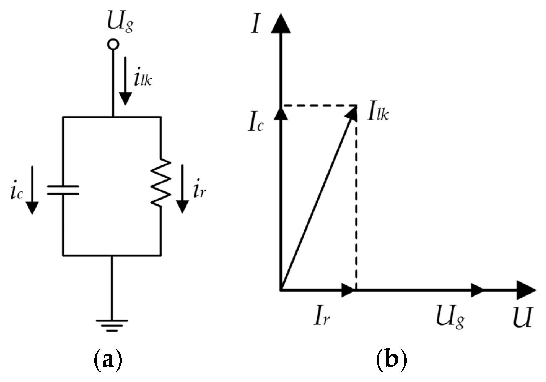
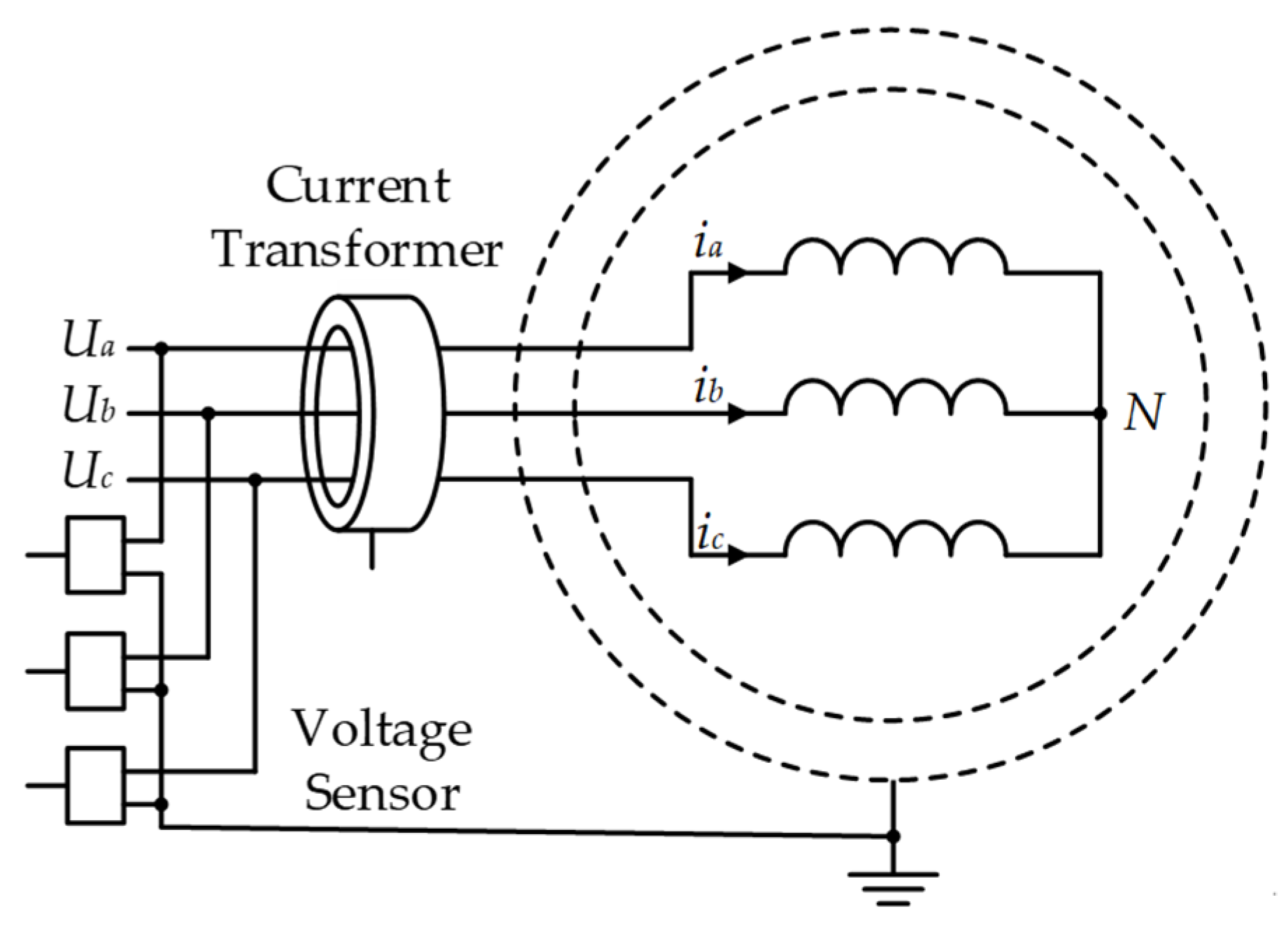
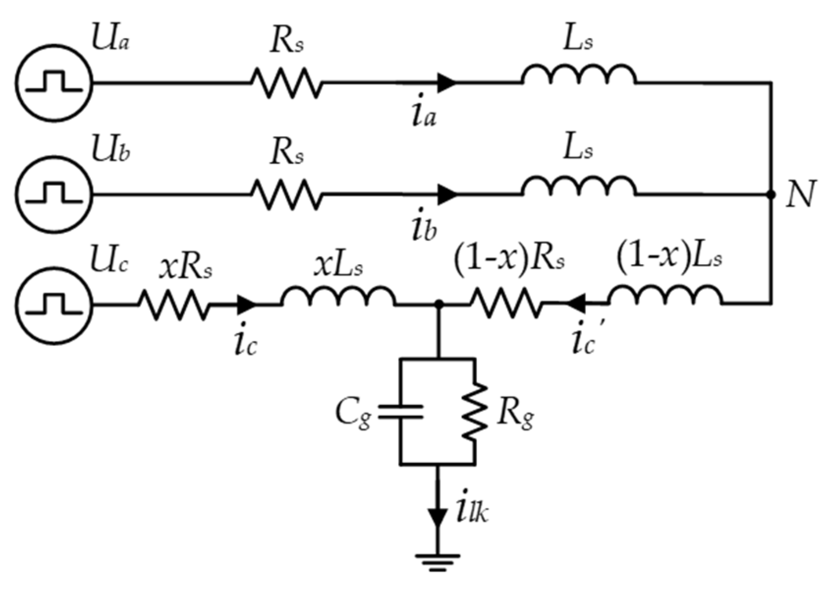
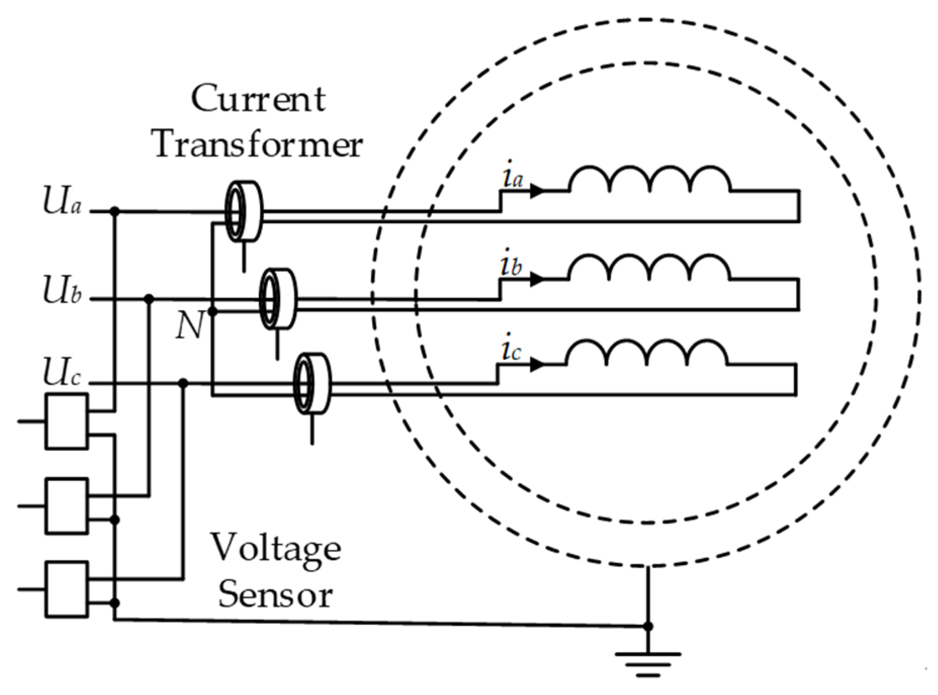
3.2. Methods Based on Time-Frequency Characteristics of Leakage Currents

As the stator winding insulation deteriorates, the layer degrades and becomes thinner, leading to delamination or voids caused by discharge phenomena and thermal effects. During this process, the insulation’s equivalent resistance gradually decreases, the equivalent capacitance increases, and the dielectric loss factor increases [59]. For inverter-driven motors, the inverter output voltage contains a wide range of frequency components [22], typically ranging from the fundamental frequency to several megahertz. Therefore, online monitoring technology based on the time–frequency characteristics of the leakage current involves analyzing the leakage current and selecting features that can reflect the degree and location of insulation aging to monitor the insulation condition.
To explore the mechanism by which insulation aging affects leakage current, it is first necessary to model and analyze the parameters of the stator winding. These parameters include the resistance and inductance of the stator winding, the groundwall insulation parameters, the inter-turn insulation parameters, the inter-phase insulation parameters, and the coupling parameters between the stator winding and components, such as the rotor and bearings [60]. A complete model is relatively complex. However, due to the low switching frequency of traditional thyristor devices, the stator winding insulation model is primarily determined by the groundwall insulation parameters, with the winding’s insulation parameters being negligible. This means that only the groundwall insulation parameters need to be considered. As a result, the insulation model of the stator winding can be represented by a parallel combination of resistive and capacitive elements, with the leakage current being decomposed into resistive and capacitive components. The simplified model and its phasor diagram of the stator winding considering the groundwall insulation aging are shown in Figure 6a,b, where Ug denotes groundwall voltage and ilk, ic, and ir denote the leakage current, capacity current, resistance current, respectively.
The inverter output voltage contains various frequency components, which can be divided into zero-sequence voltage (common-mode voltage) and non-zero-sequence voltage (differential-mode voltage) components [61]. Common-mode voltage acts on the groundwall insulation in the PWM frequency range, generating common-mode leakage current. Differential-mode voltage acts on both the groundwall and inter-phase insulation, generating differential-mode leakage current [62]. Common-mode leakage current generated by common-mode voltage is the primary means of reflecting the condition of the main insulation. Existing research can be divided into time-domain analysis [63] and frequency-domain analysis [64,65,66] according to the selected aging characteristics. The leakage current is often measured using the common-mode measurement method shown as Figure 7 [67].
For the common mode measurement method, a high-sensitivity current transformer (CT) is installed between the inverter and AC motor to measure the total leakage current driven by the common mode voltage to assess the health condition of primary insulation of stator winding. When using the total common-mode leakage current measurement, the capacitance and dissipation factor can be computed the same way as offline tests.
The time-domain method is a monitoring approach based on the transient characteristics of leakage current. In [63], the author proposed an online monitoring method for the groundwall insulation using the transient characteristics of leakage current. The primary contribution of the study lies in deriving the time-domain expression (Equations (1)–(3)) of the transient oscillation process (shown as Figure 8, where Aini, Tc, and Ts denote initial oscillation amplitudes, oscillation period of leakage current, and attenuation time of leakage current, respectively) of leakage current based on the equivalent circuit model (shown as Figure 9, where Ua, b, c denote three-phase instantaneous voltages, Rg and Cg denote the groundwall insulation resistance and capacitance, respectively, and Rs and Ls are the stator resistance and inductance, respectively. Point N is the neutral point). The study further derives expressions for the initial oscillation amplitude, oscillation period, and decay time of the leakage current. It analyzes the quantitative relationship between these expressions and the phase, location, and severity of groundwall insulation degradation, allowing for their identification.
i l k ( t ) = 2 ( Δ U c x L s + Δ U a + Δ U b ( 3 2 x ) L s ) w e α t sin ( w t 2 )
w = 12 x ( 3 2 x ) L s C g ( R s L s + 1 R g C g ) 2
α = R s L s + 1 R g C g
In Equations (1)–(3), ΔUa, b, c denote the step voltages applied to three-phase stator windings.
ω and α denote the angular frequency and the attenuation coefficient, respectively.
In contrast, the frequency-domain method is a monitoring approach that analyzes the leakage current’s time-domain characteristics. Paper [65] used the equivalent circuit model in Figure 9 and performed a Fourier decomposition of the equivalent three-phase square wave voltage to analyze the frequency-domain characteristics (Equations (4) and (5)) of the leakage current and its evolution. Unlike the time-domain method, this approach establishes significant correlations between the DC component of the leakage current and the insulation resistance, the insulation degradation location, and the fundamental and third harmonic components of the leakage current and the insulation capacitance. Compared to the time-domain method, this approach enables decoupled insulation resistance and capacitance evaluation and is effective regardless of the insulation degradation location.
U a ( t ) = U d c 2 + k = 1 2 U d c π 1 2 k 1 sin ( ( 2 k 1 ) w c t ) U b ( t ) = U d c 2 + k = 1 ( a k sin ( k w c t ) + b k sin ( k w c t ) ) U b ( t ) = U d c 2 + k = 1 ( a k sin ( k w c t ) + b k sin ( k w c t ) )
I l k ( w ) = ( 3 2 x ) U c k ( w ) + x ( U a k ( w ) + U b k ( w ) ) x ( 3 2 x ) ( R s + j w L s ) + 3 R g 1 + j w R g C g
In Equations (4) and (5), Udc denotes the DC bus voltage, ak and bk are the coefficients of the Fourier series, ωc = 2πfc is the angular frequency corresponding to the inverter switching frequency fc, Uak, bk, ck denote the k th sinusoidal components of the three-phase PWM voltage, respectively, and ω = c is the angular frequency corresponding to each harmonic component.
Building on the work of [65], a further discussion was conducted on the frequency composition of the PWM voltage through double Fourier decomposition, revealing that the variable-frequency motor voltage consists of a fundamental frequency, switching frequency harmonics, and sideband frequencies centered around the switching frequency harmonics (Equation (6)) [66]. The authors optimized and refined this work in recent literature [64]. The main contribution of the method lies in deriving expressions for common-mode and differential-mode currents at various harmonics (Equations (7) and (8)). The method offers better accuracy and effectiveness by using both common-mode and differential-mode currents to comprehensively assess insulation degradation degree and location.
U a ( t ) = U d c 2 + α U d c 2 sin ( w 0 t ) +                           m = 1 2 U d c m π J 0 ( α m π 2 ) sin m π 2 cos ( m w c t ) +                           m = 1 n = 2 U d c m π J n ( α m π 2 ) sin ( m n ) π 2 cos ( m w c t + n w 0 t )
I g , C M = 3 w C g ( 3 + j ) U d c m π J 0 ( α n π 2 ) 3 + x ( 3 2 x ) w C g ( w L s + j R s )
I g , D M = ( 3 x 3 ) w C g ( 3 + j ) U d c m π J 0 ( α n π 2 ) 3 + x ( 3 2 x ) w C g ( w L s + j R s )
In Equations (6)–(8), f0 and fc denote the fundamental frequency and carrier wave frequency, respectively, ω0 and ωc denote the fundamental angular frequency and carrier angular frequency, respectively, α denotes the modulation index, and Jk denotes the k th-order Bessel function, m = 1, 2, 3, … and n = 0, 1, 2, … denote Double Fourier decomposition coefficients.
Methods based on the leakage current rely on the equivalent circuit of the stator winding, extracting time-frequency information from the leakage current to monitor insulation degradation and developing various results that reflect the degradation location. However, since monitoring occurs within the PWM frequency range, low-frequency voltage excitation cannot generate sufficient leakage current on inter-turn insulation with minimal equivalent capacitance. Theoretically, this method lacks the ability to detect inter-turn insulation degradation. Additionally, the leakage current is generally tiny, posing high demands on the sampling accuracy of common-mode current sensors.

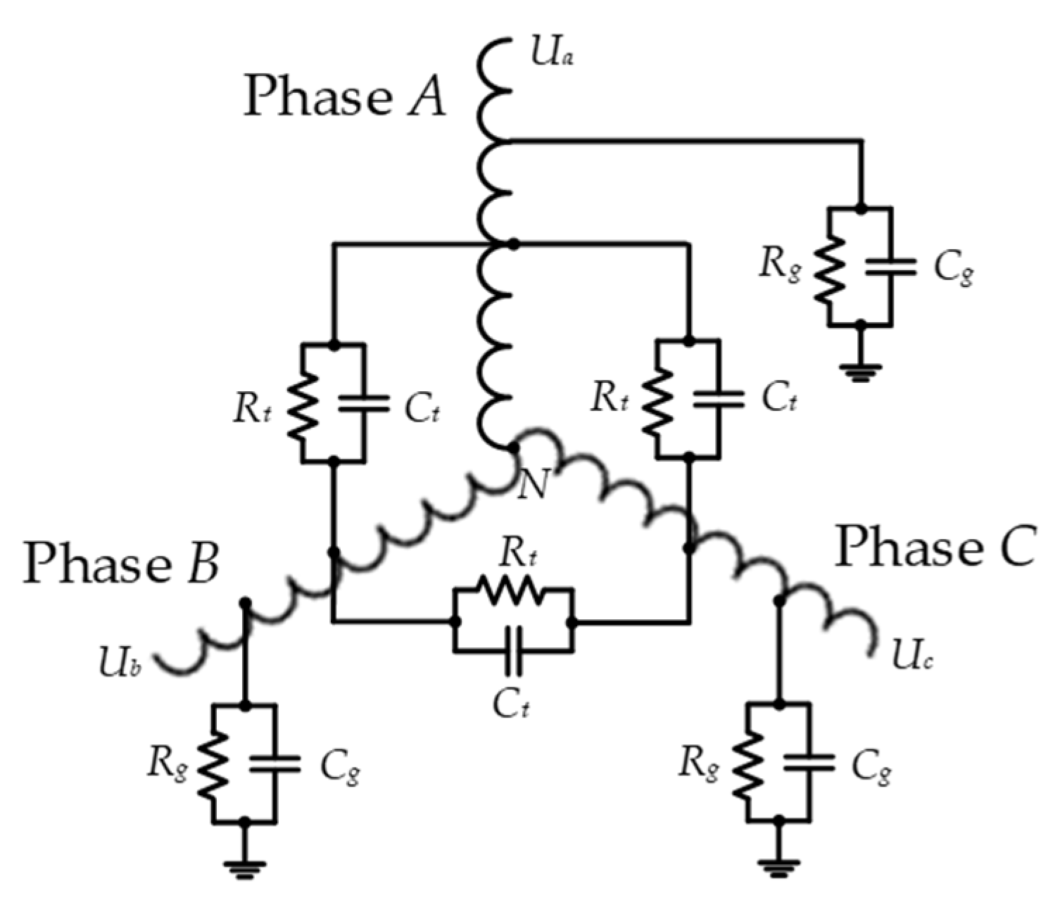
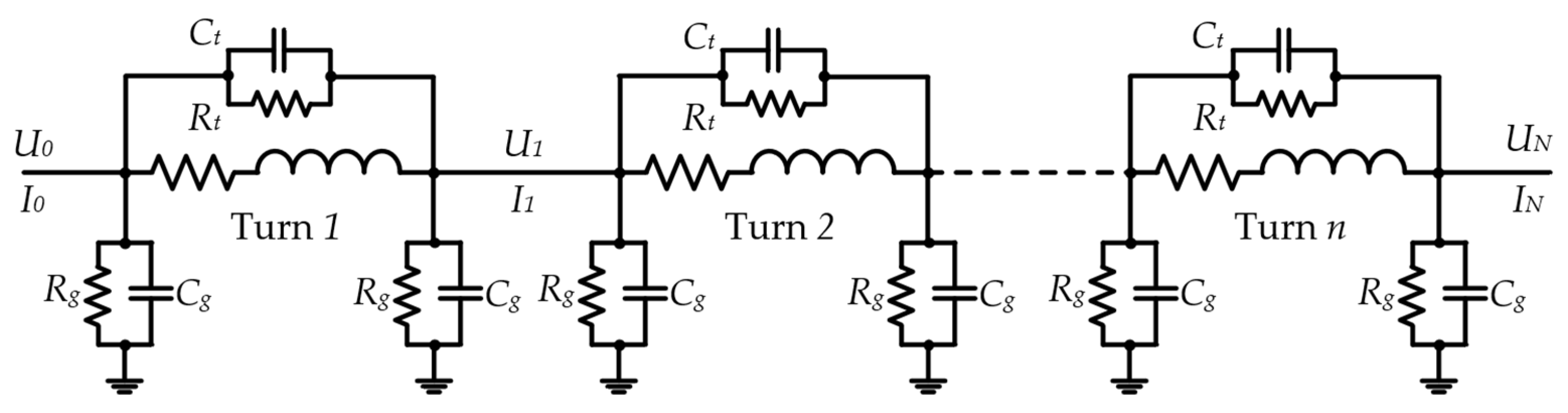
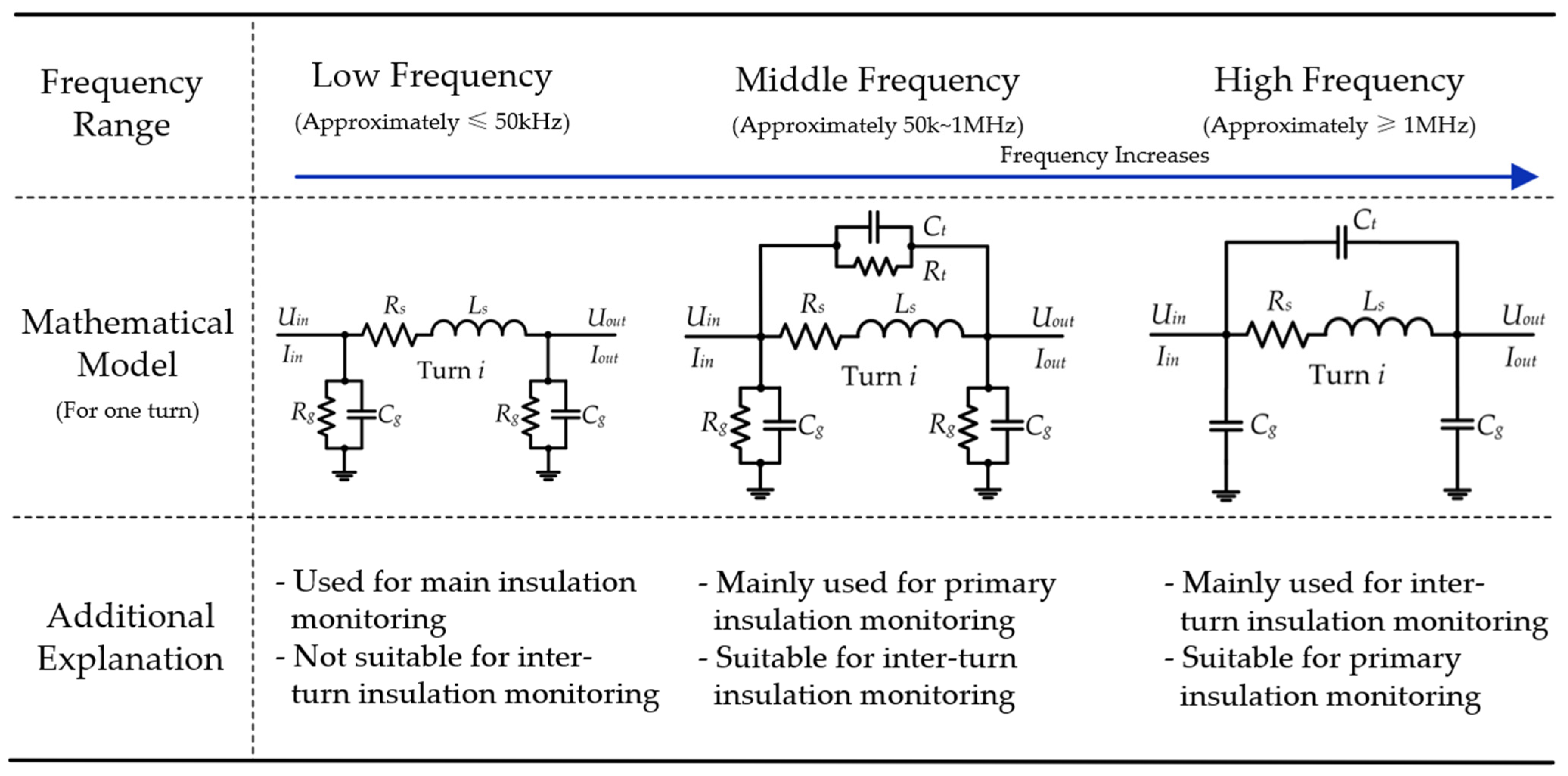
3.3. Methods Based on Broadband Impedance Spectrum

The principle of online insulation monitoring based on the broadband impedance spectrum is similar to that based on leakage current. However, by measuring the leakage current generated by input voltages at different frequencies, the impedance variation across a wide frequency range for the stator winding—known as the impedance spectrum—can be obtained. Existing research divides the impedance spectrum into PWM low-frequency harmonic, mid-frequency resonance, and high-frequency resonance regions [68], as illustrated in the Figure 10. The previously discussed online insulation monitoring method based on the leakage current operates in the PWM low-frequency harmonic region, which can reflect the aging condition of the groundwall and inter-phase insulation but cannot provide information on inter-turn insulation. This limitation is due to the minimal equivalent capacitance of the inter-turn insulation, leading to a feeble signal under low-frequency excitation. To overcome this, current research has gradually shifted towards higher-frequency excitation methods, using common-mode impedance spectroscopy to obtain resonance information in the mid-to-high frequency range, which can reflect the condition of inter-turn insulation [69]. In this scenario, the insulation parameters of the winding itself cannot be neglected. Besides the groundwall insulation’s equivalent RC branch, that of the inter-turn insulation should also be considered. This represents a significant advantage over insulation monitoring methods based on the leakage current.
To calculate the impedance spectrum, the leakage current must be measured under excitation voltages of different frequencies. The earliest idea was to apply a voltage excitation at different frequencies directly. Some studies have focused on this high-frequency voltage injection method. For example, in [70], the authors used passive coupling and a sine wave generator to produce broadband voltages ranging from 10 kHz to 9.5 MHz, achieving online CM impedance mapping through signal injection. Although this method can effectively monitor the insulation status, it has notable drawbacks. First, the high-frequency excitation signal content is relatively low because it operates in systems without a variable frequency device (VFD). Moreover, the need for additional signal injection equipment to achieve excitation at different frequencies limits its application in actual industrial settings.
As mentioned earlier, the inverter’s switching action generates excitation voltage over a wide frequency range, with rich frequency components that can provide insulation property information at different frequencies, enabling a more comprehensive analysis of the insulation state without requiring additional signal injection equipment. Standard measurement methods include common-mode measurement (same as that in Section 3.2, Figure 7) and differential-mode measurement (Figure 11) [71].
Differential mode measurement is similar to common mode measurement but involves using three voltage and three current sensors. The current transformers, typically high-sensitivity Hall effect sensors, are installed between the inverter and the motor. The incoming and outgoing leads of each phase winding are passed through the sensor in opposite directions to better measure the leakage current of that phase. Voltage sensors are used to measure the input voltage of each phase.
Zhang, Zheng, et.al. have conducted extensive research on the broadband excitation characteristics of inverters as follows:
(1)
Low-Frequency Range.
The parameters of inter-turn insulation are not considered. The overall equivalent insulation model is shown in Figure 12, where Ct and Rt denote equivalent resistance and capacitance of inter-turn insulation, respectively.
In response to the limitation of existing methods, which can only measure the overall condition of groundwall and phase-to-phase insulation, [62] proposed a new scheme for insulation monitoring using the inverter-generated switching harmonics. This method can separately monitor groundwall and phase-to-phase insulation. For the first time, the insulation capacitance at different locations can be accurately measured based on multi-frequency information, significantly improving monitoring sensitivity. In subsequent work [72], the authors further addressed the issues of unreasonable assumptions of a linear voltage drop along the stator winding for differential-mode phase-to-ground voltage and the neglect of phase angle deviations. They analyzed the impact of phase angle deviations on monitoring results and calculated compensation coefficients for different winding conditions to correct errors and enhance the accuracy of online monitoring results.
(2)
Mid- and High-Frequency Range.
The parameters of inter-turn insulation need to be considered. The segmented lumped parameter model considering inter-turn insulation under mid- and high-frequency excitation is shown in Figure 13. This model simultaneously considers the actual structure of the motor windings, making it more accurate as it better reflects real-world conditions. In this model, the input and output of the i-th winding conform to the transfer law shown in Equation (9). The voltage–current transfer equation along the coil is shown as Equations (9)–(12).
U i · I i · = Y p Z s + 1 Z s ( Y p Z s + 2 ) Y p Y p Z s + 1 U · i 1 I · i 1
U 0 · I 0 · = Y p Z s + 1 Z s ( Y p Z s + 2 ) Y p Y p Z s + 1 n U · N I · N = = A B C A n U · N 0 = A n B n C n A n U · N 0
Y p = j w C g
Z s = 1 1 R s + j w L s + 1 R t + j w C t
In Equations (9)–(12), U ˙ 0, N denote input and neutral voltage, respectively, U ˙ i (i = 1, 2, …, n) denotes the voltage at the i-th node, I ˙ t, N denote input and neutral current, respectively, Zs and Yp denote the series impedance and parallel admittance parameters, respectively.
In [73], the author proposed a new method for locating insulation aging along the winding based on switching harmonics, using the high- and low-frequency results in the common mode (CM) impedance spectrum to identify the aging location of the groundwall insulation. This method can detect local aging issues with high sensitivity and avoids existing methods’ limitations, which can only detect the overall aging of the groundwall insulation without adding additional signal injection equipment. A similar work is presented in [74]. In subsequent work [75], the authors improved this method by addressing potential false alarms caused by the motor structure. To further explore impedance-spectrum-monitoring methods for inter-turn insulation, [76] proposed an online monitoring method based on common-mode winding impedance spectroscopy for inverter-driven motor inter-turn insulation aging. This method first introduced high-frequency parallel capacitance as an indicator of inter-turn insulation aging, compared to methods using resonance frequency as an indicator [77], which avoids the impact of changes in winding inductance and resistance on inter-turn aging. Furthermore, to address the coupling problem between groundwall insulation impedance and inter-turn insulation impedance under mid-to-high frequency excitation, the authors combined data-driven methods [78] to identify fault types. In subsequent work [79], they discussed the applicability of different impedance-spectrum-monitoring methods under various types of insulation degradation.
Additionally, some studies have used impedance information for insulation life prediction. For example, in [59], the authors proposed a new low-voltage inverter-driven motor groundwall insulation monitoring method based on the multi-frequency measurement of the equivalent insulation groundwall capacitance and dissipation factor. Through accelerated aging tests on stator samples, they monitored and tracked capacitance and dissipation parameters during the aging process. To predict the failure time, they used data fitting to establish a correlation between the groundwall insulation capacitance and final life.
Compared to leakage-current-based methods, impedance-spectrum-based methods expand the monitoring frequency range to broadband, allowing for the simultaneous monitoring of multiple insulation locations (groundwall insulation, inter-phase insulation, inter-turn insulation). However, as mentioned earlier, impedance spectrum changes caused by inter-turn aging can be affected by changes due to groundwall insulation aging, limiting the application of online inter-turn insulation-monitoring methods [78]. There is still much room for exploration to solve this issue. Additionally, compared to leakage-current-based methods, impedance-spectrum-based methods further widen the frequency range of voltage and current acquisition, which poses higher requirements on the sensor bandwidth. Achieving insulation monitoring with a narrow bandwidth while ensuring accuracy is a potential research direction.

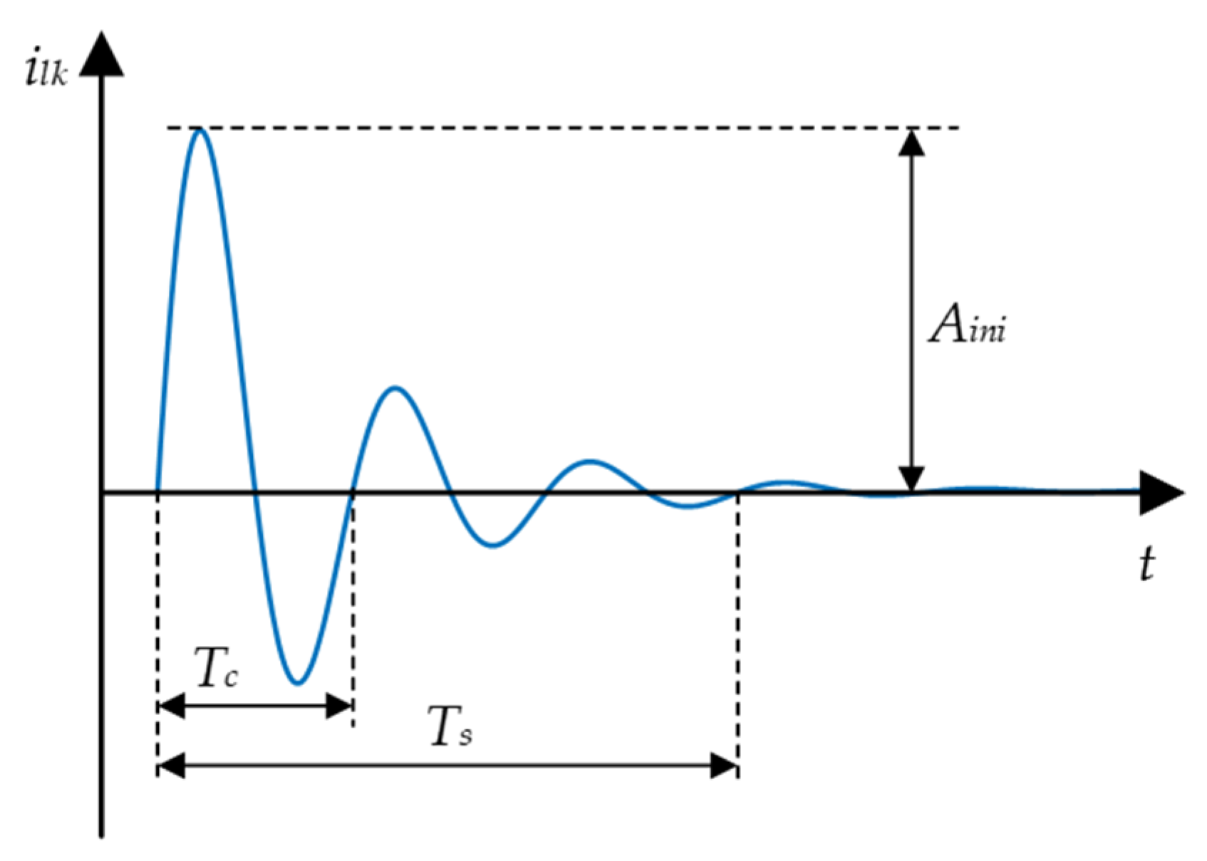
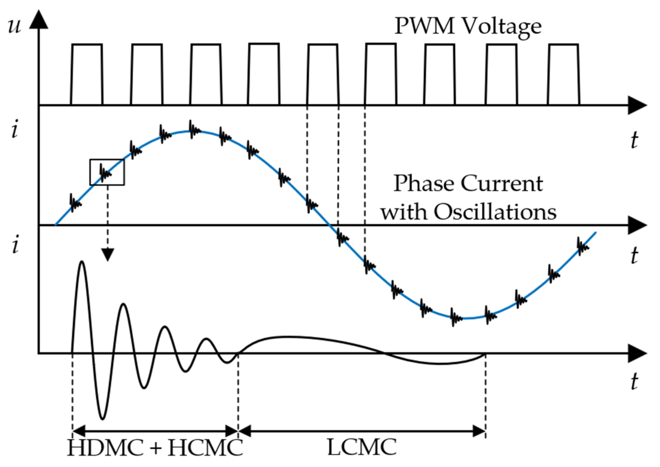
3.4. Methods Based on High-Frequency Current Ringing

When a variable-frequency drive (VFD) switches, impedance changes caused by insulation aging can alter the transient current loop, resulting in high-frequency oscillations in the transient current at the switching event, as shown in Figure 14. According to related research, this phenomenon is primarily caused by three factors [80]: (1) the inherent impedance of the machine windings; (2) voltage signal reflection due to impedance mismatch between the cable and the motor [81]; and (3) the propagation of different high-frequency current components in different modes within the winding, known as multimodal propagation [82]. Specifically, common-mode current propagation can be divided into high-frequency and low-frequency components. The high-frequency component of the CM current flows to the ground through the parasitic capacitance at the terminal and the first turn of the winding. In contrast, the low-frequency component penetrates the winding and leaks to the ground along its length. This modal decomposition of switching current is further studied in [68], as illustrated in Figure 15. The oscillations are divided into a high-frequency common mode current (HCMC), low-frequency common mode current (LCMC), and high-frequency differential mode current (HDMC). Therefore, the transient oscillations in the phase current can reflect the condition of the groundwall insulation and the inter-turn insulation. This method primarily uses current sensors within the VFD for data measurements. It offers a significant cost advantage in practical applications as it does not require additional high-precision common-mode current sensors compared to impedance spectroscopy-based methods.
In [83], the author proposed detecting this change by evaluating the transient current response immediately following inverter switching, triggered by a voltage step excitation, and applying it to small and large induction motors with different insulation systems. The results validated its applicability across different machine ratings and winding systems (e.g., random wound and form wound). In this study, a Fast Fourier Transform (FFT) was performed on the measured signal to obtain its spectrum. Different insulation condition indicators were extracted by comparing the spectra of normal and fault conditions. Similarly, in [84], tests were conducted on motors with different winding configurations, demonstrating the method’s capability to detect natural thermal aging and the presence of moisture. The method measures each phase separately, enabling phase discrimination of the indicators. Reference [85] investigated the impact of natural electrical aging on high-frequency current and offline broadband impedance. An electrical aging procedure was first defined and designed, and its effects on the three tested machines were theoretically introduced. Multiple aging indicators were quantitatively evaluated based on easily measurable macroscopic quantities, assessing the impact of electrical aging on the entire stator winding. Also, based on this method, the root mean square (RMS) and peak value indicators of current ringing were introduced to assess the machine’s insulation condition [86]. This research’s main contribution lies in comparing insulation condition indicators with existing literature, detailed discussions on the hardware and software requirements of the electric drive system, and the proposal of feasible methods for the practical implementation of this approach. This method reduces hardware specifications while maintaining monitoring performance, enabling implementation at a lower sampling frequency.
Early degradation of inter-turn insulation is an attractive but challenging issue. Xiang, Li, et al. have extensively researched early inter-turn insulation degradation. In [87], insulation health indicators were extracted from the LFCM component of the phase current based on the multimodal current propagation principle. The contribution lies in the proposed method’s good sensitivity to local initial degradation of inter-turn insulation, reflecting the degree of degradation while insensitive to operating conditions. However, the drawback is that it can only reflect the overall condition of the inter-turn insulation and cannot locate the degradation. Reference [68] studied the insulation monitoring of line-end coils under high transient voltage stress, which are with a higher risk of premature insulation breakdown. The article discusses the multimodal current propagation process in VFD systems, separating the three dominant modes in the switching oscillation current using a mode decomposition algorithm. HFCM current amplitude–frequency characteristics were proposed for condition monitoring, and the results showed high sensitivity, robustness, and non-contract safety.
Similar to impedance spectroscopy-based insulation monitoring methods, although transient current-based methods offer high performance, they still face the challenges in identifying early groundwall and inter-turn insulation degradation. This is because, at higher switching oscillation frequencies, both the groundwall and inter-turn insulation capacitances participate in the oscillation’s resonance circuit, affecting the oscillation’s characteristics. Additionally, switching the oscillation current has non-stationary characteristics. Time-domain aliasing occurs when the interval between two consecutive switching events is shorter than the duration of the switching oscillation [88]. Machine learning or deep learning-based pattern recognition methods may offer potential solutions to these challenges. Paper [89] proposed using wavelet packets to reconstruct the original switching oscillation signal, enhancing its insulation-sensitive features, and establishing a one-dimensional convolutional neural network (CNN) regression model to extract condition information from the enhanced switching oscillation signal and evaluate terminal insulation capacitance. The results verified that this method could assess the accuracy of winding terminal insulation capacitance with the pF-level. The authors further proposed a hybrid method combining physical and data-driven approaches to monitor insulation degradation in [88]. Based on the continuous wavelet transform (CWT) extraction of time–frequency characteristics of the switching oscillation, an improved CNN was used for sample classification, and the method’s sensitivity, accuracy, and robustness were validated on a low-power permanent magnet synchronous motor (PMSM) drive system. Similar methods can be found in [90].

3.5. Summary of Methods

According to the broadband theory, the windings exhibit different equivalent models across various frequency ranges. Section 3.2, Section 3.3 and Section 3.4 analyze the equivalent models for the PWM frequency range, the mid-frequency range, and the high-frequency range, respectively. In this section, a summary is applied to highlight the distinctions and connections between the different methods, as shown in Figure 16.
Additionally, to further clarify the characteristics of the discussed methods, the frequency range, monitoring locations, required sensors, advantages, and disadvantages are summarized in Table 2.

4. Conclusions and Discussion

This paper aims to provide an in-depth analysis and review of recent advancements in online electrical monitoring methods for stator winding insulation in inverter-fed motors. The review is divided into two main sections.
The first section examines the various stresses that lead to insulation failure in AC motor stator windings. These stresses are categorized into four types: electrical, thermal, mechanical, and environmental. The specific causes of insulation failure are summarized for each type of stress, and the underlying mechanisms are explained in detail. Furthermore, the coupling relationships between these four types of stresses under multi-physics conditions are analyzed. The process from the initial causes of failure to insulation degradation and ultimately to insulation breakdown is summarized across the full-time scale.
The second section summarizes the latest research on online monitoring methods for stator insulation conditions. These methods are classified into four categories: partial discharge, leakage current, broadband impedance spectrum, and high-frequency current ringing. The paper provides a detailed review of each monitoring method’s principles, methodologies, advantages, and disadvantages. The main contributions and limitations of each approach are also discussed.
For methods based on partial discharge, this review highlights its limitations in applicability, sensor placement, and susceptibility to noise interference. Currently it is not the best solution for online monitoring. Methods based on leakage current time–frequency characteristics entirely use the multi-frequency characteristics of the inverter’s output voltage. The advantages of this method include low bandwidth requirements for sensors, as measurements are conducted at low frequencies (PWM frequency range), and their ability to localize groundwall insulation degradation. However, in theory, it lacks the ability to detect the degree of inter-turn insulation degradation. Impedance spectroscopy-based methods extend the monitoring frequency range to a broadband spectrum, enabling the simultaneous monitoring of multiple insulation locations, including groundwall, phase-to-phase, and inter-turn insulation. However, this method requires additional sensors and increases the demand for the sensor bandwidth. The equipment is costly and susceptible to noise interference, and multiple insulation faults can affect the accuracy of online monitoring. Therefore, further research is needed to explore novel methods with narrow bandwidths and realize the location of degraded insulation. The transient current ringing method extracts insulation information from the transient oscillation waveforms of phase currents during switching operations. This method primarily relies on the current sensors within the inverter and does not require additional high-precision common-mode current sensors, offering a cost advantage. However, this method also faces challenges distinguishing insulation degradation at different locations. Data-driven pattern-recognition techniques have recently been applied in this area. However, their robustness and reliability in practical industrial motor applications need further validation.

Funding

This research was funded in part by the Natural Science Foundation of China (NSFC), grant number 52307065; in part by the Fundamental Research Funds for the Central Universities, China (* Corresponding author: Senyi Liu); and in part by the Key Project of China State Railway Group Co., Ltd., grant number N2023J068-B(JB).

Data Availability Statement

No new data were created or analyzed in this study. Data sharing is not applicable to this article.

Acknowledgments

The authors express their sincere appreciation to the editor and referees for their valuable time and efforts on our paper.

Conflicts of Interest

The authors declare no conflicts of interest.

References

  1. Zhang, P.J.; Du, Y.; Habetler, T.G.; Lu, B. A Survey of Condition Monitoring and Protection Methods for Medium-Voltage Induction Motors. IEEE Trans. Ind. Appl. 2011, 47, 34–46. [Google Scholar] [CrossRef]
  2. Bell, R.N.; McWilliams, D.W.; O’donnell, P.; Singh, C.; Wells, S.J. Report of Large Motor Reliability Survey of Industrial and Commercial Installations. 1. IEEE Trans. Ind. Appl. 1985, 21, 853–864. [Google Scholar]
  3. Drif, M.; Cardoso, A.J.M. Stator Fault Diagnostics in Squirrel Cage Three-Phase Induction Motor Drives Using the Instantaneous Active and Reactive Power Signature Analyses. IEEE Trans. Ind. Inform. 2014, 10, 1348–1360. [Google Scholar] [CrossRef]
  4. Tallam, R.M.; Habetler, T.G.; Harley, R.G. Experimental testing of a neural-network-based turn-fault detection scheme for induction machines under accelerated insulation failure conditions. In Proceedings of the IEEE International Symposium on Diagnostics for Electric Machines, Power Electronics and Drives, Atlanta, GA, USA, 24–26 August 2003. [Google Scholar]
  5. Zheng, D.; Zhang, P. A Review of Fault Diagnosis and Online Condition Monitoring of Stator Insulation in AC Electrical Machine. Proc. Chin. Soc. Electr. Eng. 2019, 39, 395–406. [Google Scholar]
  6. Mazzoletti, M.A.; Bossio, G.R.; De Angelo, C.H.; Espinoza-Trejo, D.R. A Model-Based Strategy for Interturn Short-Circuit Fault Diagnosis in PMSM. IEEE Trans. Ind. Electron. 2017, 64, 7218–7228. [Google Scholar] [CrossRef]
  7. Sahin, I.; Keysan, O. Model Predictive Controller Utilized as an Observer for Inter-Turn Short Circuit Detection in Induction Motors. IEEE Trans. Energy Conver 2021, 36, 1449–1458. [Google Scholar] [CrossRef]
  8. Mahmoudi, A.; Jlassi, I.; Marques Cardoso, A.J.; Yahia, K.; Sahraoui, M. Inter-Turn Short-Circuit Faults Diagnosis in Synchronous Reluctance Machines, Using the Luenberger State Observer and Current’s Second-Order Harmonic. IEEE Trans. Ind. Electron. 2022, 69, 8420–8429. [Google Scholar] [CrossRef]
  9. Ehya, H.; Nysveen, A. Pattern Recognition of Interturn Short Circuit Fault in a Synchronous Generator Using Magnetic Flux. IEEE Trans. Ind. Appl. 2021, 57, 3573–3581. [Google Scholar] [CrossRef]
  10. Chen, Y.; Rehman, A.U.; Zhao, Y.; Wang, L.; Wang, S.; Zhang, M.; Zhao, Y.; Cheng, Y.; Tanaka, T. Numerical Modeling, Electrical Characteristics Analysis and Experimental Validation of Severe Inter-Turn Short Circuit Fault Conditions on Stator Winding in DFIG of Wind Turbines. IEEE Access 2021, 9, 13149–13158. [Google Scholar] [CrossRef]
  11. Zhang, J.; Xu, Z.; Wang, J.; Zhao, J.; Din, Z.; Cheng, M. Detection and Discrimination of Incipient Stator Faults for Inverter-Fed Permanent Magnet Synchronous Machines. IEEE Trans. Ind. Electron. 2021, 68, 7505–7515. [Google Scholar] [CrossRef]
  12. Oner, M.U.; Sahin, I.; Keysan, O. Neural Networks Detect Inter-Turn Short Circuit Faults Using Inverter Switching Statistics for a Closed-Loop Controlled Motor Drive. IEEE Trans. Energy Conver 2023, 38, 2387–2395. [Google Scholar] [CrossRef]
  13. Toma, S.; Capocchi, L.; Capolino, G.-A. Wound-Rotor Induction Generator Inter-Turn Short-Circuits Diagnosis Using a New Digital Neural Network. IEEE Trans. Ind. Electron. 2013, 60, 4043–4052. [Google Scholar] [CrossRef]
  14. Shih, K.-J.; Hsieh, M.-F.; Chen, B.-J.; Huang, S.-F. Machine Learning for Inter-Turn Short-Circuit Fault Diagnosis in Permanent Magnet Synchronous Motors. IEEE Trans. Magn. 2022, 58, 8204307. [Google Scholar] [CrossRef]
  15. Grubic, S.; Aller, J.M.; Lu, B.; Habetler, T.G. A Survey on Testing and Monitoring Methods for Stator Insulation Systems of Low-Voltage Induction Machines Focusing on Turn Insulation Problems. IEEE Trans. Ind. Electron. 2008, 55, 4127–4136. [Google Scholar] [CrossRef]
  16. IEEE 275-1992; IEEE Recommended Practice for Thermal Evaluation of Insulation Systems for Alternating-Current Electric Machinery Employing Form-Wound Preinsulated Stator Coils for Machines Rated 6900 V and Below. IEEE: Piscataway, NJ, USA, 1992; pp. 1–14. [CrossRef]
  17. Cai, Z.; Wang, X.; Li, L.; Hong, W. Electrical treeing: A phase-field model. Extrem. Mech. Lett. 2019, 28, 87–95. [Google Scholar] [CrossRef]
  18. Dehlinger, N.; Stone, G. Surface partial discharge in hydrogenerator stator windings: Causes, symptoms, and remedies. IEEE Electr. Insul. Mag. 2020, 36, 7–18. [Google Scholar] [CrossRef]
  19. Lee, H.; Kim, H.; Jeong, J.; Lee, K.; Lee, S.B.; Stone, G. Inverter-Embedded Partial Discharge Testing for Reliability Enhancement of Stator Winding Insulation in Low Voltage Machines. IEEE Trans. Ind. Appl. 2022, 58, 2088–2096. [Google Scholar] [CrossRef]
  20. Tang, Y.; Liu, X.; Wang, J.; Guo, Y.; Liu, Y.; Li, D. Electrical Tree Characteristics in Winding Insulation for Inverter-fed Traction Motor under Repetitive Impulse Voltages. High Volt. Eng. 2023, 49, 2625–2633. [Google Scholar]
  21. Sun, P.; Sima, W.; Jiang, X.; Zhang, D.; He, J.; Ye, L. Review of accumulative failure of winding insulation subjected to repetitive impulse voltages. High Volt. 2019, 4, 1–11. [Google Scholar] [CrossRef]
  22. Li, H.; Liu, J.Y.; Xiang, D.W.; Gu, Y. Feature Extraction and Decoupling of Line-end Coil Insulation for Inverter-fed Machine Using High-frequency Differential Mode Switching Oscillation. Proc. Chin. Soc. Electr. Eng. 2024, 44, 1608–1618. [Google Scholar] [CrossRef]
  23. IEC TS 61934:2024; Electrical Insulating Materials and Systems–Electrical Measurement of Partial Discharges (PD) under Short Rise Time and Repetitive Voltage Impulses. IEC: New York, NY, USA, 2024; pp. 1–31.
  24. Liu, K.; Zhang, K.; Hua, W.; Hu, M.J. Efficiency Optimization Control of Permanent Magnet Synchronous Motor Drive System Based on Variable Carrier Frequency. J. Southeast Univ./Dongnan Daxue Xuebao 2024, 54, 724–729. [Google Scholar]
  25. Farahani, M.; Gockenbach, E.; Borsi, H.; Schaefer, K.; Kaufhold, M. Behavior of Machine Insulation Systems Subjected to Accelerated Thermal Aging Test. IEEE Trans. Dielectr. Electr. Insul. 2010, 17, 1364–1372. [Google Scholar] [CrossRef]
  26. Chen, P.; Xie, Y.; Li, D. Thermal Field and Stress Analysis of Induction Motor with Stator Inter-Turn Fault. Machines 2022, 10, 504. [Google Scholar] [CrossRef]
  27. Istad, M.; Runde, M.; Nysveen, A. A Review of Results from Thermal Cycling Tests of Hydrogenerator Stator Windings. IEEE Trans. Energy Conver. 2011, 26, 890–903. [Google Scholar] [CrossRef]
  28. Siddique, A.; Yadava, G.S.; Singh, B. A review of stator fault, monitoring techniques of induction motors. IEEE Trans. Energy Conver. 2005, 20, 106–114. [Google Scholar] [CrossRef]
  29. Lin, F.; Zuo, S.; Deng, W.; Wu, S. Modeling and Analysis of Electromagnetic Force, Vibration, and Noise in Permanent-Magnet Synchronous Motor Considering Current Harmonics. IEEE Trans. Ind. Electron. 2016, 63, 7455–7466. [Google Scholar] [CrossRef]
  30. Stone, G.C.; Maughan, C.V.; Nelson, D.; Schultz, R.R. Impact of slot discharges and vibration sparking on stator winding life in large generators. IEEE Electr. Insul. Mag. 2008, 24, 14–21. [Google Scholar] [CrossRef]
  31. Rauber, A.; den Bakker, P. Stator End-Winding Vibration in Two-Pole Machines: Avoiding Generator Failure. IEEE Ind. Appl. Mag. 2020, 26, 56–66. [Google Scholar] [CrossRef]
  32. Zhang, H.; Zhang, M.; Wang, X. Fracture failure analysis of insulation with initial crack defect for stator end-winding in induction motor by using magnetic-structural coupling model. Eng. Fail. Anal. 2023, 149, 107239. [Google Scholar] [CrossRef]
  33. Fernando, M.A.R.M.; Naranpanawa, W.M.L.B.; Rathnayake, R.M.H.M.; Jayantha, G.A. Condition Assessment of Stator Insulation during Drying, Wetting and Electrical Ageing. IEEE Trans. Dielectr. Electr. Insul. 2013, 20, 2081–2090. [Google Scholar] [CrossRef]
  34. Maughan, C.V. Root-cause diagnostics of generator service failures. In Proceedings of the IEEE International Symposium on Electrical Insulation, Indianapolis, IN, USA, 19–22 September 2004. [Google Scholar]
  35. Stone, G. Examples of premature stator winding failure in recently manufactured motors and generators. In Proceedings of the 10th Insucon International Conference Birmingham 2006, Birmingham, UK, 24–26 May 2006; pp. 217–220. [Google Scholar]
  36. Guedes, A.S.; Silva, S.M.; Cardoso Filho, B.d.J.; Conceicao, C.A. Evaluation of electrical insulation in three-phase induction motors and classification of failures using neural networks. Electr. Power Syst. Res. 2016, 140, 263–273. [Google Scholar] [CrossRef]
  37. Xiang, A.F. Insulation-failure Analysis of Traction Motor of High-speed EMU. Railw. Locomot. Car 2023, 43, 120–125. [Google Scholar]
  38. Wheeler, J.C.G. Effects of converter pulses on the electrical insulation in low and medium voltage motors. EEE Electr. Insul. Mag. 2005, 21, 22–29. [Google Scholar] [CrossRef]
  39. Sundeep, S.; Wang, J.; Griffo, A.; Alvarez-Gonzalez, F. Antiresonance Phenomenon and Peak Voltage Stress within PWM Inverter Fed Stator Winding. IEEE Trans. Ind. Electron. 2021, 68, 11826–11836. [Google Scholar] [CrossRef]
  40. Vala, S.S.; Mirza, A.B.; Emon, A.I.; Luo, F. A Review of Partial Discharge in Stator Winding of Rotating Machines Fed by Voltage Source PWM Motor Drives. IEEE Trans. Ind. Appl. 2024, 60, 3790–3807. [Google Scholar] [CrossRef]
  41. Ogundiran, Y.L.; Griffo, A.; Sundeep, S.; Wang, J. A Novel Embedded Sensor for Partial Discharge Detection in Inverter-Fed Machines. IEEE Trans. Ind. Appl. 2022, 58, 4698–4707. [Google Scholar] [CrossRef]
  42. Zhou, W.; Wang, P.; Zhao, Z.; Wu, Q.; Cavallini, A. Design of an Archimedes Spiral Antenna for PD Tests under Repetitive Impulsive Voltages with Fast Rise Times. IEEE Trans. Dielectr. Electr. Insul. 2019, 26, 423–430. [Google Scholar] [CrossRef]
  43. Li, J.; Wang, P.; Jiang, T.; Bao, L.; He, Z. UHF Stacked Hilbert Antenna Array for Partial Discharge Detection. IEEE Trans. Antennas Propag. 2013, 61, 5798–5801. [Google Scholar] [CrossRef]
  44. Ashari, F.; Khayam, U. Design and fabrication of vivaldi antenna as partial discharge sensor. In Proceedings of the 2017 4th International Conference on Electric Vehicular Technology (ICEVT), Bali, Indonesia, 2–5 October 2017; pp. 76–78. [Google Scholar]
  45. Nakamura, K.; Uchimura, T.; Kozako, M.; Hikita, M.; Ueno, T.; Sun, J.; Sakurai, T.; Nakayama, K.; Ikegami, T.; Karasawa, K.; et al. Comparison of Sensor Detection Sensitivity in Repetitive Partial Discharge Inception Voltage Measurement for Twisted Pair Placed in Stator. In Proceedings of the IEEE Conference on Electrical Insulation and Dielectric Phenomena (IEEE CEIDP), Toronto, ON, Canada, 16–19 October 2016. [Google Scholar]
  46. Stone, G.C.; Sedding, H.G.; Chan, C. Experience with Online Partial-Discharge Measurement in High-Voltage Inverter-Fed Motors. IEEE Trans. Ind. Appl. 2018, 54, 866–872. [Google Scholar] [CrossRef]
  47. Alvarez-Gonzalez, F.; Hewitt, D.; Griffo, A.; Wang, J.; Diab, M.; Yuan, X. Design of Experiments for Stator Windings Insulation Degradation under High dv/dt and High Switching Frequency. In Proceedings of the 12th Annual IEEE Energy Conversion Congress and Exposition (IEEE ECCE), Detroit, MI, USA, 10–15 October 2020. [Google Scholar]
  48. Tozzi, M.; Cavallini, A.; Montanari, G.C. Monitoring Off-line and On-line PD under Impulsive Voltage on Induction Motors—Part 2: Testing. EEE Electr. Insul. Mag. 2011, 27, 14–21. [Google Scholar] [CrossRef]
  49. Tozzi, M.; Cavallini, A.; Montanari, G.C. Monitoring Off-Line and On-Line PD under Impulsive Voltage on Induction Motors—Part 1: Standard Procedure. EEE Electr. Insul. Mag. 2010, 26, 16–26. [Google Scholar] [CrossRef]
  50. Billard, T.; Lebey, T.; Castelan, P.; Deville, Y. Partial discharge monitoring in twisted pair using non-intrusive sensors: Numerical analysis. In Proceedings of the IEEE Annual Report Conference on Electrical Insulation and Dielectric Phenomena (CEIDP), Shenzhen, China, 20–23 October 2013. [Google Scholar]
  51. Stone, G.C.; Warren, V. Objective methods to interpret partial-discharge data on rotating-machine stator windings. IEEE Trans. Ind. Appl. 2006, 42, 195–200. [Google Scholar] [CrossRef]
  52. Abadie, C.; Billard, T.; Lebey, T. Partial Discharges in Motor Fed by Inverter: From Detection to Winding Configuration. IEEE Trans. Ind. Appl. 2019, 55, 1332–1341. [Google Scholar] [CrossRef]
  53. Stone, G.C. Condition Monitoring and Diagnostics of Motor and Stator Windings—A Review. IEEE Trans. Dielectr. Electr. Insul. 2013, 20, 2073–2080. [Google Scholar] [CrossRef]
  54. Li, Y.; Li, Z. Application of a Novel Wavelet Shrinkage Scheme to Partial Discharge Signal Denoising of Large Generators. Appl. Sci. 2020, 10, 2162. [Google Scholar] [CrossRef]
  55. Wang, P.; Li, P.; Akram, S.; Meng, P.; Zhu, G.; Montanari, G.C. Considering the Parameters of Pulse Width Modulation Voltage to Improve the Signal-to-Noise Ratio of Partial Discharge Tests for Inverter-Fed Motors. IEEE Trans. Ind. Electron. 2022, 69, 4545–4554. [Google Scholar] [CrossRef]
  56. Ghosh, R.; Seri, P.; Hebner, R.E.; Montanari, G.C. Noise Rejection and Detection of Partial Discharges under Repetitive Impulse Supply Voltage. IEEE Trans. Ind. Electron. 2020, 67, 4144–4151. [Google Scholar] [CrossRef]
  57. Rauscher, A.; Kaiser, J.; Devaraju, M.; Endisch, C. Deep learning and data augmentation for partial discharge detection in electrical machines. Eng. Appl. Artif. Intell. 2024, 133, 108074. [Google Scholar] [CrossRef]
  58. Chen, Y.; Peng, X.; Wang, H.; Zhou, J.; Zhang, Y.; Liang, Z. Generator Stator Partial Discharge Pattern Recognition Based on PRPD-Grabcut and DSC-GoogLeNet Deep Learning. IEEE Trans. Dielectr. Electr. Insul. 2023, 30, 2267–2276. [Google Scholar] [CrossRef]
  59. Tsyokhla, I.; Griffo, A.; Wang, J. Online Condition Monitoring for Diagnosis and Prognosis of Insulation Degradation of Inverter-Fed Machines. IEEE Trans. Ind. Electron. 2019, 66, 8126–8135. [Google Scholar] [CrossRef]
  60. Zhang, P.J.; Zheng, D.Y. A Review of Broadband Stator Winding Modelling Methods for Insulation Condition Monitoring in Inverter⁃fed Machines. Navig. Control 2021, 20, 38–51. [Google Scholar]
  61. Pan, L.; Du, X.; Lei, X.; Ye, T.; Xiang, D.; Li, H. Double-ring high-frequency common-mode switching oscillation current sensor for inverter-fed machine winding insulation monitoring. Glob. Energy Interconnect. 2024, 7, 106–116. [Google Scholar] [CrossRef]
  62. Zheng, D.; Zhang, P. An Online Groundwall and Phase-to-Phase Stator Insulation Monitoring Method for Inverter-Fed Machine. IEEE Trans. Ind. Electron. 2021, 68, 5303–5313. [Google Scholar] [CrossRef]
  63. Niu, F.; Wang, Y.; Huang, S.; Wu, L.; Huang, X.; Fang, Y.; Yang, T. An Online Groundwall Insulation Monitoring Method Based on Transient Characteristics of Leakage Current for Inverter-Fed Motors. IEEE Trans. Power Electr. 2022, 37, 9745–9753. [Google Scholar] [CrossRef]
  64. Huang, S.; Zhang, P.; Liu, L.; Niu, F.; Sun, Q.; Li, K.; Cao, Y.; Fang, Y. Diversified Assessment of Ground-Wall Insulation in Inverter-Fed Motors by Using Transient Characteristics of Leakage Current. IEEE Trans. Power Electr. 2024, 39, 13783–13794. [Google Scholar] [CrossRef]
  65. Wang, Y.; Niu, F.; Zhang, J.; Huang, X.; Wu, L.; Fang, Y. Online monitoring method of groudwall insulation based on frequency domain characteristics of leakage current for inverter-fed motors. Electr. Mach. Control 2022, 26, 114–121. [Google Scholar]
  66. Zhang, C.; Niu, F.; Sun, Q.; Huang, S.; Zhang, J.; Li, K.; Fang, Y. Online Monitoring of Ground-Wall Insulation Condition in Inverter-Fed Motors Using Multi-Frequency Characteristics of Leakage Current. Electr. Mach. Control 2023, 27, 64–72. [Google Scholar]
  67. Zhang, P.; Younsi, K.; Neti, P. A Novel Online Stator Ground-Wall Insulation Monitoring Scheme for Inverter-Fed AC Motors. IEEE Trans. Ind. Appl. 2015, 51, 2201–2207. [Google Scholar] [CrossRef]
  68. Li, H.; Gu, Y.; Xiang, D.; Zhang, P.; Yue, P.; Cui, Y. Online Condition Monitoring of Line-End Coil Insulation for Inverter-Fed Machine by Switching Oscillation Mode Decomposition. IEEE Trans. Ind. Electron. 2022, 69, 11697–11708. [Google Scholar] [CrossRef]
  69. Ruiz-Sarrio, J.E.; Antonino-Daviu, J.A.; Navarro-Navarro, A.; Biot-Monterde, V. Broadband Technique Analysis for Insulation Fault Detection and Condition Monitoring in Rotating Electrical Machines. In Proceedings of the 2023 IEEE 14th International Symposium on Diagnostics for Electrical Machines, Power Electronics and Drives (SDEMPED), Chania, Greece, 28–31 August 2023; pp. 574–580. [Google Scholar]
  70. Neti, P.; Grubic, S. Online Broadband Insulation Spectroscopy of Induction Machines Using Signal Injection. IEEE Trans. Ind. Appl. 2017, 53, 1054–1062. [Google Scholar] [CrossRef]
  71. Lee, S.B.; Yang, J.; Younsi, K.; Bharadwaj, R.M. An online groundwall and phase-to-phase insulation quality assessment technique for AC-machine stator windings. IEEE Trans. Ind. Appl. 2006, 42, 946–957. [Google Scholar]
  72. Zhang, P.; Zheng, D.; Lu, G. The Effect and Compensation of Phase Angle Deviation along the Winding for the Online Stator Insulation Condition Monitoring. IEEE Trans. Ind. Electron. 2022, 69, 8440–8451. [Google Scholar] [CrossRef]
  73. Zheng, D.; Zhang, P. A novel method of monitoring and locating stator winding insulation ageing for inverter-fed machine based on switching harmonics. In Proceedings of the 2020 IEEE Energy Conversion Congress and Exposition (ECCE), Detroit, MI, USA, 11–15 October 2020; pp. 4474–4479. [Google Scholar]
  74. Jiang, Z.; Jia, Z.; Ma, C.; Song, W.; Zhang, B. A New Method for Monitoring Grounding Insulation Degradation of Induction Motors Based on Common-Mode Switching Transients. In Proceedings of the 2024 IEEE 10th International Power Electronics and Motion Control Conference (IPEMC2024-ECCE Asia), Chengdu, China, 7–20 May 2024; pp. 2690–2694. [Google Scholar]
  75. Zheng, D.; Lu, G.; Zhang, P. An Improved Online Stator Insulation Monitoring Method Based on Common-Mode Impedance Spectrum Considering the Effect of Aging Position. IEEE Trans. Ind. Appl. 2022, 58, 3558–3566. [Google Scholar] [CrossRef]
  76. Zheng, D.; Lu, G.; Zhang, P. A Noninvasive Interturn Insulation Condition Monitoring Method Based on the Common-Mode Impedance Spectrum of Inverter-Fed Machines. IEEE Trans. Ind. Appl. 2021, 57, 4786–4795. [Google Scholar] [CrossRef]
  77. Werynski, P.; Roger, D.; Corton, R.; Brudny, J.F. Proposition of a new method for in-service monitoring of the aging of stator winding insulation in ac motors. IEEE Trans. Energy Conver. 2006, 21, 673–681. [Google Scholar] [CrossRef]
  78. Zheng, D.; Lu, G.; Wu, Y.; Zhang, Q.; Zhang, P. Online Detection and Classification of Interturn and Groundwall Insulation Aging Based on Broadband Common-Mode Impedance Spectrum. IEEE Trans. Ind. Electron. 2024, 71, 3142–3153. [Google Scholar] [CrossRef]
  79. Zheng, D.; Lu, G.; Qu, J.; Zhang, Y.; Zhang, P. Comparative Study of Neutral-Voltage-Based and Leakage-Current-Based Online Condition Monitoring Methods for Stator Insulation of Inverter-Fed Machines. IEEE Trans. Ind. Electron. 2024, 1–11. [Google Scholar] [CrossRef]
  80. Ruiz-Sarrio, J.E.; Antonino-Daviu, J.A.; Navarro-Navarro, A.; Biot-Monterde, V. A Review of Broadband Frequency Techniques for Insulation Monitoring and Diagnosis in Rotating Electrical Machines. IEEE Trans. Ind. Appl. 2024, 60, 6092–6102. [Google Scholar] [CrossRef]
  81. Kerkman, R.J.; Leggate, D.; Skibinski, G.L. Interaction of drive modulation and cable parameters on AC motor transients. IEEE Trans. Ind. Appl. 1997, 33, 722–731. [Google Scholar] [CrossRef]
  82. Ran, L.; Gokani, S.; Clare, J.; Bradley, K.J.; Christopoulos, C. Conducted electromagnetic emissions in induction motor drive systems part I: Time domain analysis and identification of dominant modes. IEEE Trans. Power Electr. 1998, 13, 757–767. [Google Scholar] [CrossRef]
  83. Nussbaumer, P.; Vogelsberger, M.A.; Wolbank, T.M. Induction Machine Insulation Health State Monitoring Based on Online Switching Transient Exploitation. IEEE Trans. Ind. Electron. 2015, 62, 1835–1845. [Google Scholar] [CrossRef]
  84. Zoeller, C.; Vogelsberger, M.A.; Fasching, R.; Grubelnik, W.; Wolbank, T.M. Evaluation and Current-Response-Based Identification of Insulation Degradation for High Utilized Electrical Machines in Railway Application. IEEE Trans. Ind. Appl. 2017, 53, 2679–2689. [Google Scholar] [CrossRef]
  85. Leuzzi, R.; Monopoli, V.G.; Rovere, L.; Cupertino, F.; Zanchetta, P. Analysis and Detection of Electrical Aging Effects on High-Speed Motor Insulation. IEEE Trans. Ind. Appl. 2019, 55, 6018–6025. [Google Scholar] [CrossRef]
  86. Zanuso, G.; Peretti, L. Evaluation of High-Frequency Current Ringing Measurements for Insulation Health Monitoring in Electrical Machines. IEEE Trans. Energy Conver. 2022, 37, 2637–2644. [Google Scholar] [CrossRef]
  87. Xiang, D.; Li, H.; Yan, H.; Zheng, Y.; Zhao, N.; Liu, B. Online Monitoring of Incipient Turn Insulation Degradation for Inverter-Fed Machine Using Sensitive Tail Component in PWM Switching Oscillations. IEEE Trans. Power Electr. 2021, 36, 8730–8742. [Google Scholar] [CrossRef]
  88. Li, H.; Yu, J.; Xiang, D.; Han, J.; Wu, Q. A Hybrid Physics-Based and Data-Driven Approach for Monitoring of Inverter-Fed Machine Stator Insulation Degradations Using Switching Oscillations. IEEE Trans. Ind. Inform. 2024, 20, 9527–9538. [Google Scholar] [CrossRef]
  89. Yu, J.; Li, H.; Cheng, R.; Liu, J.; Li, Y. Data-driven condition monitoring of stator winding terminal insulation for inverter-fed machine using enhanced switching oscillation signals. IEICE Electron. Expr. 2022, 19, 20220435. [Google Scholar] [CrossRef]
  90. Fan, R.T.; Li, H. Inverter-fed Machine Turn Insulation Condition Monitoring Based on FrFT-CNN. J. Shanghai Univ. Electr. Power 2024, 1–7. Available online: https://link.cnki.net/urlid/31.2175.tm.20240701.1719.006 (accessed on 25 September 2024).
Figure 1. Common fault types in AC motors.
Wevj 15 00444 g001
Figure 2. Multi-factor aging model in IEEE 275.
Wevj 15 00444 g002
Figure 3. The growth process of the electrical tree.
Wevj 15 00444 g003
Figure 4. Main stresses of insulation degradation and their interrelationships.
Wevj 15 00444 g004
Figure 5. Schematic diagram of stator winding aging process.
Wevj 15 00444 g005
Figure 6. Simplified model (a) and its phasor diagram (b) of the stator winding.
Wevj 15 00444 g006
Figure 7. Common-mode measurement method.
Wevj 15 00444 g007
Figure 8. Transient oscillation process.
Wevj 15 00444 g008
Figure 9. Equivalent circuit model.
Wevj 15 00444 g009
Figure 10. Division of low-, mid- and high-frequency area.
Wevj 15 00444 g010
Figure 11. Differential mode measurement method.
Wevj 15 00444 g011
Figure 12. Equivalent insulation model for low frequency.
Wevj 15 00444 g012
Figure 13. Equivalent insulation model for mid- and high- frequency.
Wevj 15 00444 g013
Figure 14. High frequency current ringing.
Wevj 15 00444 g014
Figure 15. Modal decomposition of switching current.
Wevj 15 00444 g015
Figure 16. Summary of mathematical models.
Wevj 15 00444 g016
Table 1. Stress type, impact factor, and performance.
Stress TypeImpact FactorPerformance
Electrical Stresscumulative effect of high frequency pulsesinsulation partial discharge
transient voltageelectrical tree discharge
Thermal Stressthermal degradationdeterioration of insulation materials
thermal fluctuationinsulation material deformation
Mechanical Stressloose wire rods in the slotinsulation material detachment
vibration of stator windingwear of insulation materials
Ambient Stressdirtycorrosion of insulation materials
water strainscarbonization burn marks
scratchesscratches on insulation materials
Table 2. Summary of reviewed methods.
MethodsFrequency
Range
Monitoring
Locations
Additional
Sensors
Main
Advantages
Main
Disadvantages
Partial DischargeHigh
frequency
Almost all1. Intrusive detection coils or antennas
2. High-bandwidth current sensors
1. High precision
2. Able to reflect most insulation aging information
1. Not applicable to low-voltage motors
2. Hard to balance non-invasiveness and accuracy
3. Susceptible to noise interference
4. Additional sensors required
Time–Frequency CharacteristicsLow
frequency
Primary
insulation
High-sensitivity
current transformer
1. Low bandwidth requirements for sensors
2. Able to monitoring the location of degradation
1. Unable to monitor inter-turn insulation
2. Additional sensors required
Broadband Impedance SpectrumMiddle
frequency
Primary
insulation and
Inter-phase
insulation and
Inter-turn
insulation
High-sensitivity
current transformer
1. Able to monitor multiple locations
2. Able to monitoring the location of degradation
1. Additional sensors required
2. Higher bandwidth sensors needed
3. Hard to distinguish in cases of multi-location degradation
High-Frequency Current RingingMiddle
frequency
High
frequency
Mainly inter-
turn insulation
None1. No additional sensors required
2. Better monitoring of inter-turn insulation
1. Presence of multimodal aliasing
2. Potential for temporal aliasing
Disclaimer/Publisher’s Note: The statements, opinions and data contained in all publications are solely those of the individual author(s) and contributor(s) and not of MDPI and/or the editor(s). MDPI and/or the editor(s) disclaim responsibility for any injury to people or property resulting from any ideas, methods, instructions or products referred to in the content.

