Article

Orderly Charging Control of Electric Vehicles: A Smart Meter-Based Approach

1
State Grid Hangzhou Power Supply Company, Hangzhou 310016, China
2
College of Electrical Engineering, Zhejiang University, Hangzhou 310027, China
3
Polytechnic Institute, Zhejiang University, Hangzhou 310015, China
*
Author to whom correspondence should be addressed.
World Electr. Veh. J. 2024, 15(10), 449; https://doi.org/10.3390/wevj15100449
Submission received: 14 August 2024 / Revised: 20 September 2024 / Accepted: 27 September 2024 / Published: 3 October 2024

Abstract

:
The charging load of electric vehicles (EV) is one of the most rapidly increasing loads in current power distribution systems. It may cause distribution transformer/feeder overload without proper coordination or control, especially in residential area where household load and EV charging load are sharing transformer capacity. Existing smart meter-based orderly charging control (OCC) approaches commonly require costly but unreliable communication schemes to control EV charging behavior. In this work, a smart meter-based distributed controller is designed to establish a meter-to-EV communication interface with low cost and enhanced reliability, based on the state-of-the-art charging standard. An event-driven OCC algorithm is developed, and then, deployed in the data hub (concentrator) of the AMI with an easy-to-implement optimization formulation. The effectiveness of the proposed approach is validated using a numerical case study and a practical field test in Hangzhou, China. Both results indicate promising advantages of the proposed OCC approach in reducing the peak load of emerging EV charging demand by more than 30 % .

1. Introduction

The rapid adoption of electric vehicles (EVs) is transforming the transportation sector worldwide, offering significant environmental benefits by reducing greenhouse gas emissions and reliance on fossil fuels. Charging facilities, including charging piles and charging/switching stations, have become an important component in sustainable mobility, which serves a key role of electrified infrastructure [1]. Taking China as an example [2,3], by the end of 2023, the number of EVs in China reached 20.41 million, accounting for 6.07 % of the total number of vehicles. In the year of 2023 alone, 7.43 million new EVs were registered, making up 30.25 % of all new vehicle registrations. Compared to the number of EVs in 2022, there was an overall increase of 82.2 % . From 0.333 million in 2019 to 2.456 million in 2023: the growth rate has been remarkably high.
However, the increasing number of EVs presents new challenges for the electrical grid [4], including inadequate power supply capacity [5] and low-voltage transformer overloading [6], etc. This is because traditional power grids are not designed to handle the high and unpredictable emerging load spikes caused by simultaneous charging of massive EVs, potentially leading to grid outages and increasing costs. This situation underscores the necessity for an effective and intelligent charging management system. Orderly charging control (OCC) is an effective approach to relieve the feeder/transformer overloading issues above [7], which is especially identified as a bottleneck in residential areas [8], where most of the charging piles are privately owned and communication availability is limited. Moreover, OCC in residential areas may benefit EV and household owners; however, a win–win business scheme between utility companies and EV owners has yet to be established.
In the existing literature, there is a number of approaches to achieve OCC for EVs. Vehicle-to-grid (V2G) or bidirectional charging enables EVs to supply power back to the grid [9], enhancing grid reliability through aggregating the dispatching capability of EVs into virtual energy storage [10]. Electricity price guidance employs dynamic pricing schemes to encourage off-peak charging [11], leveraging economic incentives to shift charging loads away from peak times. Demand response programs adjust power usage of household appliances [12] and across residential buildings [13], balancing overall energy demand. Voltage control in distribution networks, based on sensitivity information [14], ensures robust and efficient power distribution by adjusting voltage levels according to load changes caused by EVs. Data-driven simulators of EV charging behavior [15] predict and manage charging patterns by analyzing historical data, aiding in effective control strategies and infrastructure planning. These approaches collectively enhance the loadability in EV-charging-intensive areas by optimizing energy use and accommodating the increasing number of EVs.
Among the aforementioned OCC approaches, smart meter-based approaches are specially favored [16], primarily due to the following considerations:
  • No additional investment on newly installed controllers is required, such as RTUs (remote terminal units) or DTUs (data transfer units);
  • No additional investment on EV-to-cloud communication is required; existing advanced metering infrastructure (AMI) can be reused;
  • Better compatibility across EV makes, due to no hardware/software upgrades to EV’s local controller;
  • Inheriting utility billing methods to facilitate business schemes for EV–grid interaction.
Given the impressive advantages of smart meter-based OCC, two major challenges have to be solved before this particular technology is able to be widely applied to practical applications:
  • The communication interface between the smart meter and EV’s onboard controller has to be conveniently and reliably established;
  • A distributed OCC algorithm has to be simple to implement yet scalable in existing AMI systems, so as to respond to operational requirements.
In order to overcome the two technical difficulties identified above, this work proposes a smart meter-based OCC approach, inheriting the idea from the authors’ previous work [17] of a communication-free control scheme for OCC. The smart meter’s capability of local sensing and computing [18] (such localized intelligence enabled various advanced features [19]) is exploited to set up communication with EVs and achieve OCC through the global coordination of AMI.
The remaining part of this work is arranged as follows. Section 2 defines the problem to be solved and visualizes it in an illustrative framework. Section 3 presents the necessary hardware and communication development in order to link up smart meter-based AMI with EVs. Section 4 provides a complete algorithmic solution to achieve OCC functionality. Section 5 further verifies the effectiveness of the proposed approach via numerical simulations; and Section 6 validates the feasibility of the proposed idea through a practical field test in an underground parking lot of a residential area in Hangzhou, China. The conclusions are summarized in Section 7.

2. Problem Statement of Orderly Charging Control

In order to provide an illustrative problem statement of the proposed OCC approach, the basic idea of this work is presented in Figure 1 with an example of a residential area.
Basically, this diagram includes three households and three sets of charging piles and EVs. The number of loads can be arbitrary as long as they can be served within the capacity of transformer and feeder. All the household loads and charging piles are monitored by smart meters. The power supply of the studied area is served by a distribution transformer, converting medium-voltage 10 kV AC to low-voltage 380 V AC. The typical capacity of such a distribution transformer in an urban system is around 600–800 kVA. Note that only one line diagram is present for the sake of brevity, but the system can be either three-phase or single-phase. The proposed hardware and algorithm solution can be applied without the loss of generalization. The power connection described above is shown in red solid lines in the figure.
Enabled by the Internet of Things (IoT) capability of modern smart meters, they are able to acquire voltage/current information of metered load (either household or EV). Such information is collected by a data hub (commonly called a concentrator in real-world AMI systems) from meters via power line communication (PLC). The collected information is further transferred to the cloud-side of an AMI through a cellular approach, such as wireless 4G or 5G. The data link described above is shown in blue dashed lines in the figure.
Following the description of the studied system above, we are able to provide a preliminary problem statement of the OCC for a group of EVs, that is, given the basic load condition (e.g., household loads in Figure 2), the power capacity constraint of the distribution transformer, and the charging demand of EVs, the goal of OCC is to determine the suggested power and time for each EV without significantly affecting the cost of EV charging, which follows the price chart of the time-of-use (TOU) tariff from the utility. Since the plug-in events of EVs are stochastic in nature, an ideal OCC scheme should be able to address such events by gathering charging request information and deciding the proper arrangement in terms of time slot and its power limit, so as to satisfy EV charging demand and stay below the transformer capacity limit at the same time.
According to the discussion in Section 1, we have identified the meter–EV interface and OCC algorithm as the two major challenges to be solved in the proposed approach, which are shown in the figure as well and are comprehensively discussed in Section 3 and Section 4, respectively. The designed meter–EV interface enables the communication between the smart meter and EV onboard controller through a simple and reliable wired connection, exploiting the current industry standard of charging pile definition. The developed OCC algorithm is embedded in the programmable data hub, where the loading condition of the distribution transformer is also monitored.

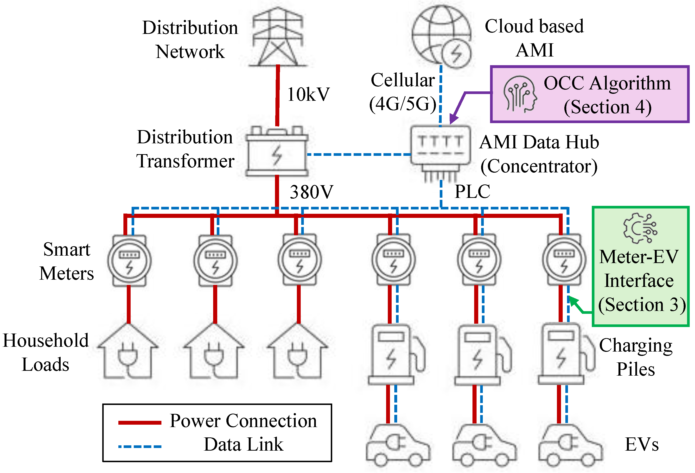
3. Smart Meter-Based Control Scheme

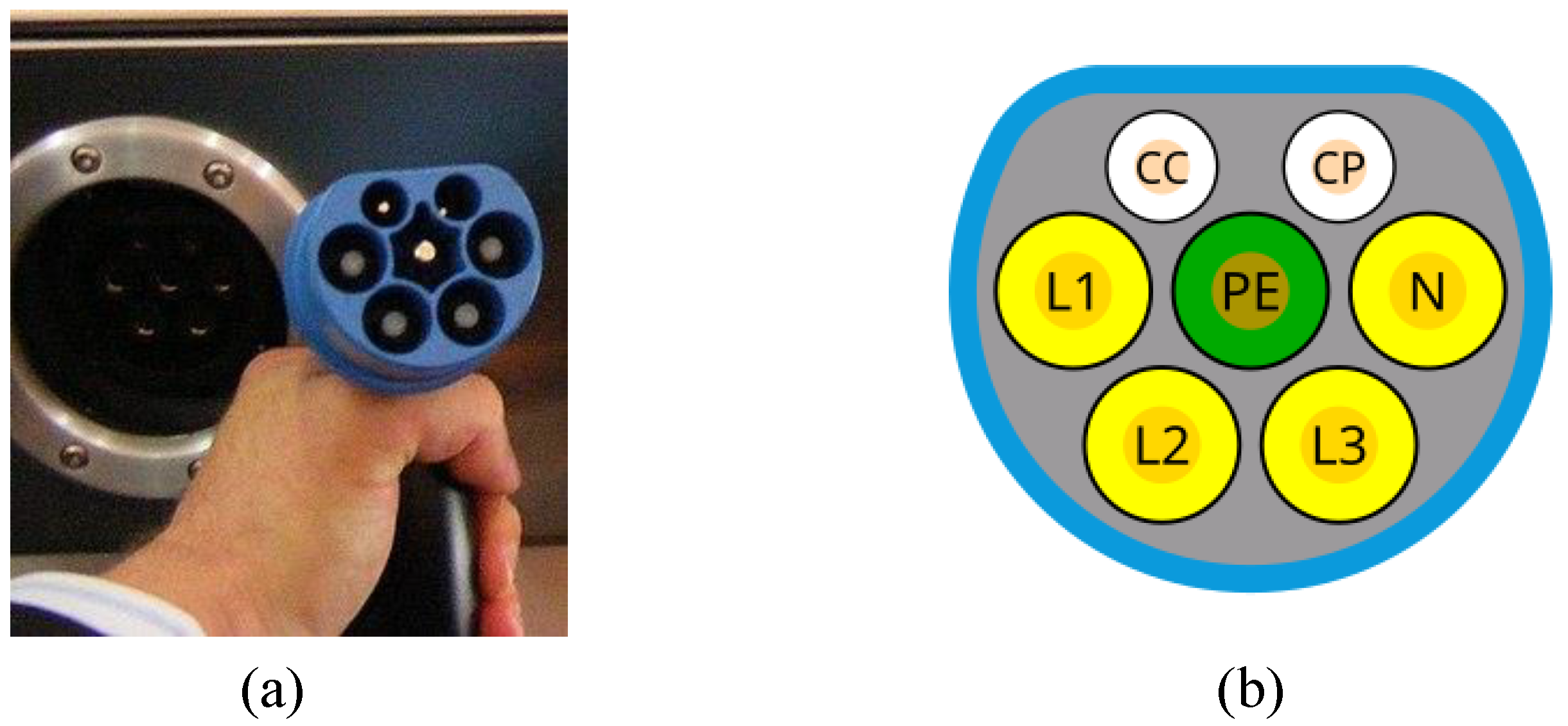
3.1. EV Communication Interface

Existing research establishes communication between a smart meter and EV primarily using a wireless connection, such as Bluetooth or Wi-Fi. Also, most EV manufacturers offer cellular connection capability in an onboard telematics box (T-Box) and allow EV owners to control charging behaviors. However, these wireless solutions may encounter significant issues in underground parking lots, where barrier shielding and electro-magnetic interference make wireless connections unstable to use. Therefore, this work designs a wired solution following the charging standards GB/T 18487.1 (corresponding to IEC 61851) and GB/T 20234.1 (corresponding to IEC 62196 and SAE J1772) [20], which are widely adopted in China and other major countries in the world [21]. In the following discussion, we focus on EVs with AC charging piles, that means charging the battery using an onboard charger (OBC). OCC applied to EVs with DC charging piles can be much easier, since off-board DC charging piles are commonly equipped with a local controller and ready to communicate with smart meters through conventional interface like RS485. OBCs are widely equipped on EVs with AC charging sockets. An OBC is essentially a power electronics converter that rectifies grid AC to onboard battery DC, so as to charge the onboard battery. Such a charging process is managed by the battery management system (BMS), which is also onboard.
The proposed meter–EV interface is based on CC/CP wires, shown in Figure 2.
According to GB/T 18487.1 (corresponding to IEC 61851), the voltage between the CC and CP wires follows the signal of a voltage oscillator, where a pulse-width modulation waveform is used to control the charging behavior of the connected EV, as shown in Figure 3. The duty cycle (D) determines the maximum available charging current specially for digital communication when 0 % < D 5 % . The detailed relationships between the duty cycle D and corresponding commands are listed in Table 1. In existing commercial charging piles on the market, the duty cycle is fixed, e.g., 25 % for 3.3 kW or 50 % for 7.7 kW, which are the most sold single-phase 220 V models in the Chinese EV market.
Therefore, we are able to develop a dedicated control module in the smart meter to generate the PWM signal to limit the maximum charging current of the EV and fetch necessary charging demand data, which is discussed in the next subsection, via CC/CP voltage signals. These two signaling wires are re-used in the AC charging piles, so as to achieve direct communication from the smart meter to the EV. Since these two wires are part of the charging socket and plug, they are connected/disconnected simultaneously with single-phase (L1 and N) or three-phase (L1, L2, L3 and N) AC power lines, as shown in Figure 2. Hence, their connection is simple but reliable.
Based on the observation of the existing standard and the proposed idea, the following meter–EV interface is designed as shown in Figure 4. The block OBC shown in Figure 4 actually represents the OBC inverter itself as well as the onboard battery and its BMS. It not only receives AC current from the charging pile, but also detects the duty cycle from CC/CP wires to determine the maximum charging current.
In Figure 4, the switch in the vehicle-end AC charging control guide circuit should support on/off control at frequencies above 1 kHz to achieve CP signal voltage control functionality. The onboard response module controls charging power based on the PWM duty cycle of the CC/CP signal. Upon detecting a 5 % duty cycle, the vehicle should upload complete vehicle information (including battery capacity, rated power of the onboard charger, current state of charge (SOC), target SOC, usage time, vehicle identification number, and acceptance of OCC, etc.) to the smart meter according to the GB/T 18487.1 communication protocol. Note that such functionality can be simply achieved by a software upgrade of the OBC subsystem on the vehicle side, which can be included as a part of an over-the-air (OTA) update.
As for the control module on the meter side, it is presented in the next subsection.

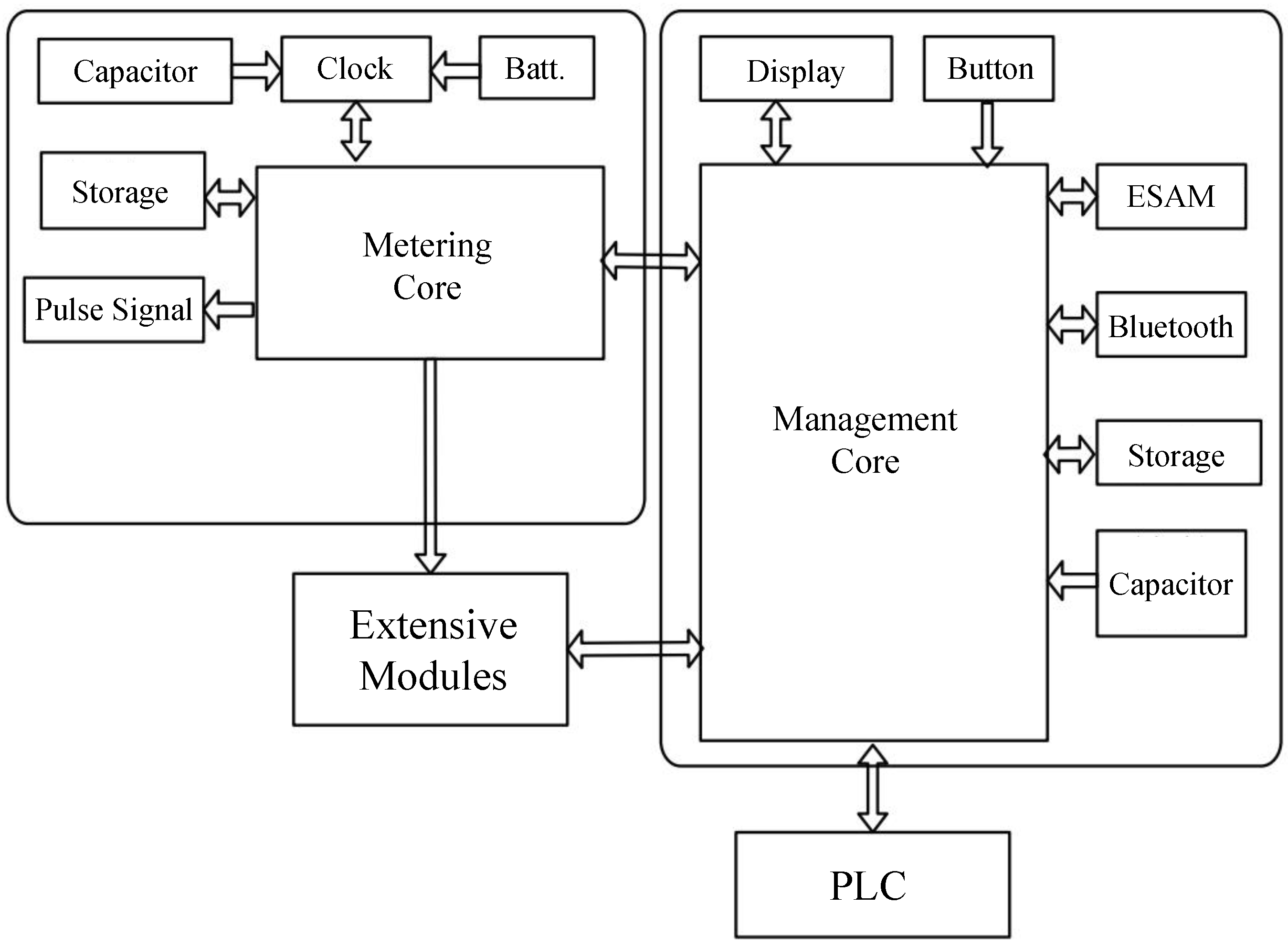
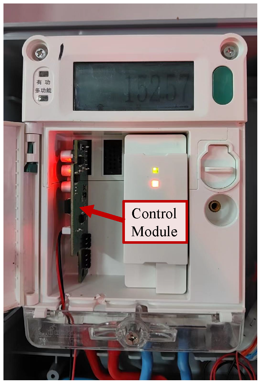
3.2. Meter-Side Control Module

The meter-side control module is implemented in the form of an extensive module in a smart grid, following the standard of modular smart meters from the State Grid Cooperation of China (SGCC) [22], corresponding to DL/T 1490-2015 [23]. The architectural framework of the modular and multi-core design is shown in Figure 5.
As shown in Figure 5, it comprises multiple modules and units, which communicate data through a high-speed bus to ensure data transmission effectiveness. The base meter includes the metering core module, responsible for legal metrology-related tasks and data collection and freezing; the management core module handles management functions such as electricity billing, schedule management, etc.; the uplink communication module facilitates communication with data hubs (concentrators), supporting PLC communication. Extensive modules can interact with the management core module and metering core module, and can be defined to perform various IoT applications. Each module operates independently and is isolated from the others.
The developed extensive module establishes a bidirectional communication link to the downstream EV, enabling control of the CC/CP and switching between orderly and conventional charging modes. The smart meter with the designed OCC control module has essentially two tasks: (1) collecting charging demand information (e.g., target time/SOC, current SOC, etc.) from the EV and reporting such information to the AMI data hub (concentrator); and (2) receiving the charging time slot and corresponding maximum current settings from AMI data hub and applying such a limit to the EV via CC/CP duty-cycle signals. Therefore, the computational requirement for the smart meter is actually negligible; the resultant control module is easy to design and implement. This is especially true when the smart meter follows a modular design, as shown in Figure 5, which is actually the most commonly installed model in the SGCC in recent years.

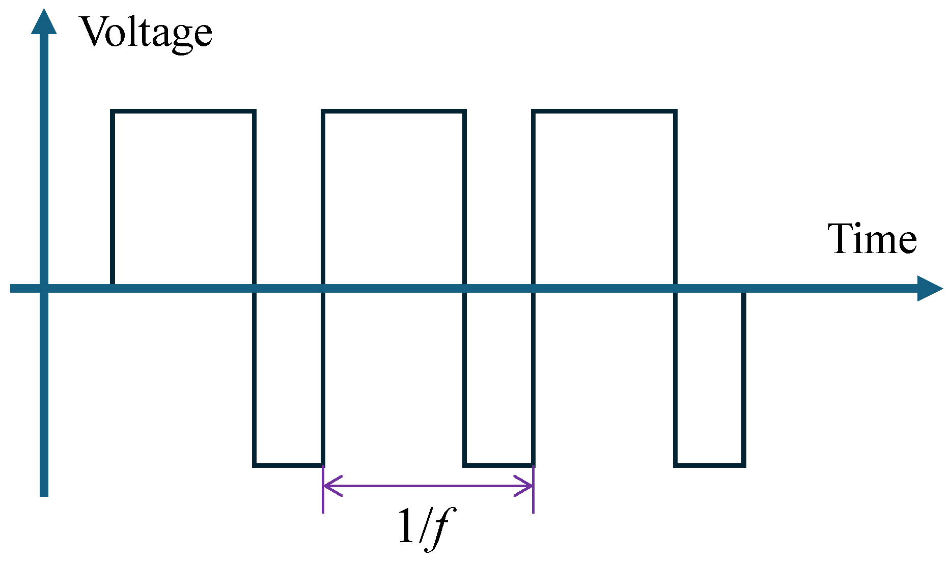
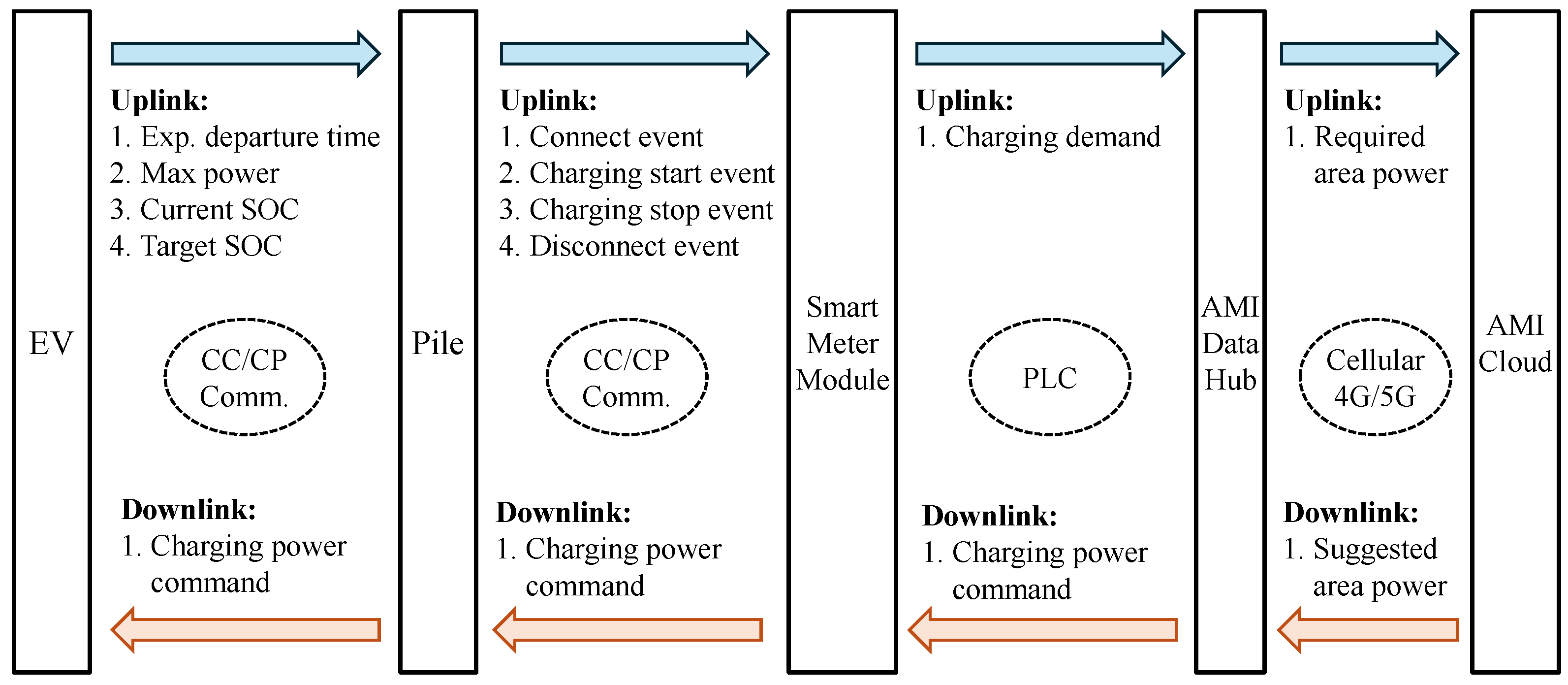
3.3. Communication Protocol

The detailed communication protocol between each component in the loop is shown in Figure 6. As we can observe, the proposed approach is able to acquire additional information, such as current/target SOC level, expected departure time, user identification, etc., which are beyond conventional charging facilities. The additional information above enables us to complete the OCC algorithm, which is described in the next section.

4. Orderly Charging Control Algorithm

The proposed OCC approach consists of three key components:
  • Day-ahead baseline load forecasting, including total EV charging load and household load, as described in Section 4.1. It provides us a general baseline to be considered in the optimization formulation.
  • Event-driven scheme, determining when and how to trigger the (re-)solution of the optimization formulation, which is explained with details in Section 4.2.
  • Optimization formulation, it optimally determines or adjusts the EV charging time slot and corresponding current limit using a linear programming program, which is covered in Section 4.3.
In the remaining part of the section, we cover all the three components as follows.

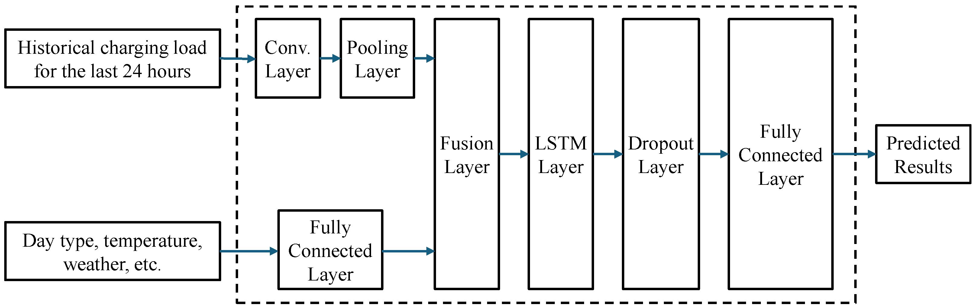
4.1. EV and Load Prediction

As the first step to perform OCC for a group of EVs, shown in Figure 1, forecasting should be performed for both the EVs and the household load. This is because they occupy the capacity of the same distribution transformer. Due to the load pattern difference, the EV charging load and household load are predicted individually, in a day-ahead manner. Although the proposed OCC approach works with all kinds of prediction algorithms [24], we will briefly introduce the EV charging load forecasting method employed in the numerical simulation and field test for the remaining part of this subsection. For a detailed algorithm description, prospective readers are suggested to refer to our previous research work [25,26] related to this topic.
To predict day-ahead EV charging load, first we need to determine the features that affect the predicted charging load. The Pearson coefficient (1) is used to perform correlation analysis.
ρ X , Y = cov ( X , Y ) σ X σ Y
where X and Y are the input and output time-series data. cov ( X , Y ) represents the covariance of them. σ X and σ Y denote the standard deviations of X and Y, respectively. The correlation coefficient ranges from 1 to 1. A value of 1 indicates a perfect positive correlation between the two random variables, while a value of 1 indicates a perfect negative correlation. A value of 0 signifies that there is no linear relationship between the two variables.
Based on the correlation analysis, we find that the past 24 h charging load data, weekday/weekend/holiday information, and externally predicted weather conditions have significant impact on the predict charging load. Therefore, the following convolutional neural networks (CNNs) and long short-term memory (LSTM)-based neural network model, shown in Figure 7, is developed to conduct the forecasting.
In Figure 7, the model structure is composed of three parts. The first part is the CNN module, which takes historical EV charging load data as input to extract features from the historical data. The second part is a dense layer that processes the impact relationships of three influencing factors: temperature, weather conditions, and day type. The third part, which is the core of the model, contains an LSTM layer followed by dropout and fully connected layers. The input to this part is the concatenated feature vector generated from the other two parts. The LSTM module can further extract temporal features from the data, enhancing the accuracy of predictions.

4.2. Event-Driven Scheme

Due to the inherent randomness and uncertainty in user charging behavior, there is a margin of error in day-ahead charging demand forecasts, meaning that vehicles in the studied residential area are unlikely to charge exactly as predicted. To enhance the timeliness and accuracy of the OCC strategy, it is necessary to employ an event-driven intra-day rolling optimization scheme to achieve precise optimization.
The triggering conditions of the event-driven scheme include:
  • EV plug-in event;
  • Transformer loading rate warning event;
  • Fixed timer to start a new day (the beginning of a day);
  • Significant deviation between forecast and actual load observed event.
For the former two situations, a real-time adjustment optimization is performed; the detailed formulation can be found in the next subsection. For the latter two, forecasting has to be started/restarted before the optimization. Especially for the fourth one, triggering by this event indicates the previous forecasting is not reliable and is now introducing significant errors for OCC. Note that the beginning of a day in the first condition is artificially set as noon of each day. This is especially useful for residential areas because most of the charging demand is observed in the afternoon, evening, or during the night. Making noon the beginning of a day leads to a much simpler formulation and less computational burden.
Also, we would like to emphasize that an EV plug-out event can be considered as a triggering event in theory but it is ignored here in order to reduce the number of triggered events. If an EV finishes charging before the scheduled time or below the scheduled SOC target, the spared charging capacity can be automatically recycled in the next triggering event. In practice, we find that ignoring the EV plugging-out event enables us to reduce the number of triggering events by around 40 % but it has almost no impact on the OCC performance in terms of accommodating more EV charging demand. This significantly reduces the required communication and computing resource for both smart meter and data hub.

4.3. Optimization Formulation

Based on the proposed event-driven scheme, we are able to focus on the mathematical formulation details of the rolling optimization. Once it is invoked by the event-driven scheme, an optimization problem is solved to find out the optimal charging arrangement for the new incoming EV and seek for a better charging arrangement of the existing connected EVs.
The formulated optimization model uses the current moment to the next 24 h as the control period, aiming to minimize overall user charging costs and the maximum load during the control period. Various constraints are applied to calculate and determine the charging power curve for each charging station within this time frame. We divide the time length of a day into 96 intervals, that is, 15 min for each time interval. This setting is sufficient for most TOU tariff schemes used in utility companies.
Detailed formulations are developed as follows.

4.3.1. Sets, Parameters, and Variables

Let N and J represent the number of all EVs in the studied area and time intervals. n and j are corresponding numbering subscripts. Δ t is the length of each time interval, which is 15 min in this paper. c j is the cost of the j-th time interval according to the TOU tariff scheme. S denotes the transformer/feeder capacity in kW. R j and L j are the predicted total household load and EV charging load for the j-th interval; note that L j should be subtracted by the target EV charging demand once it is connected. For each charging pile, its maximum power is P max ; α is the margin of loading rate of the distribution transformer, which is commonly set as 20 % by the utility company. η is the charging efficiency of the OBC in the EV, which is set as 95 % .
Once a new EV with the number n is connected to the pile (with connection to the smart meter via CC/CP wires), the following data are obtained immediately:
  • Maximum charging power P max , n , which is commonly 3.3 or 7.7 kW for most AC piles used in China;
  • Current SOC in terms of energy E n , 1 ¯ ;
  • Expected departure time, in terms of the number of the time interval, j D , n ;
  • Expected SOC at the time of departure, in terms of energy, E n , j D ¯ .
Therefore, we are able to set up the binary parameters u n , j to indicate the allowed charging period. These values need to be loaded once they are received from the smart meter.
u n , j = 1 , n 1 N , j 1 j D , n u n , j = 0 , otherwise
To perform optimization, the decision variables include the planned charging power and the SOC of the n-th EV at the j-th time interval ( P n , j and E n , j ).

4.3.2. Objective Function

The objective function is set as minimizing the total cost of EV charging and the maximum load rating.
min P n , j , E n , j j = 1 J n = 1 N c j P n , j Δ t + M Z
Note that the second term in the objective function is the impact of the maximum load rating of the distribution transformer. M is a weighting coefficient to balance the two terms, while Z is the maximum load rating. It is defined in the constraints.

4.3.3. Constraints

Z is the maximum load rating, which is a temporary variable taking the maximum of every time interval, as shown in (4). Since the max operator cannot be directly processed by an existing mathematical programming language, it is converted to a number of inequality constraints, as shown in (5).
Z = max j n = 1 N P n , j + R j + L j α S T S T , 0
Z n = 1 N P n , j + R j + L j α S T S T , 0 , j = 1 J Z 0
The maximum charging power of each EV at each time interval is regulated by the status parameter u n , j , as (6).
u n , j P n , j u n , j P max , n , j = 1 J , n = 1 N
The SOC in terms of energy is continuous along time intervals as in (7).
E n , j + 1 = E n , j + Δ t P n , j , j 1 J 1 , n = 1 N
The initial and target SOC levels for each EV are determined as constraints (8) and (9).
E n , j A = E n , j A ¯ , n = 1 N
E n , j D E n , j D ¯ , n = 1 N
Based on the formulations above, we are able to establish the optimization model to be solved every time an invoking event occurs. Note that the developed formulation only contains continuous variables and is essentially a linear programming problem; the computational burden to solve it in an embedded system like a data hub (concentrator) is minimum.

5. Numerical Results

In order to validate the effectiveness of the proposed OCC approach, a numerical case study is firstly performed before a practical field test. It assumes the meter–EV communication is perfect, so as to quantitatively evaluate the potential of OCC.
The TOU tariff rate for low-voltage residential customers by SGCC in Hangzhou, China, is used in the case study, as shown in Table 2. We investigate a fictitious case in a residential area with a household hold around 400 kW in the peak period. A total number of 70 EVs are considered with their corresponding behavior emulated according to practical charging data. The capacity of the distribution transformer is set as 600 kVA.
Based on the aforementioned case study setup and the developed event-driven OCC approach, the operational results without and with OCC of the studied residential area are shown in Figure 8, with the blue line as the transformer capacity limit. As can be observed from the figures, the total load power exceeds the transformer capacity limit during the evening time period before applying OCC; this is because the TOU rate is low starting from 22:00, guiding EV owners to set their charging timer to this period. After applying OCC to this case, most of the charging loads are shifted from the evening time period to the early morning time period, making the peak level significantly lower than the situation without OCC. Also, the OCC approach can reduce residential charging costs by approximately 35 % , from 1114.9 Chinese yuan (CNY) to 728.2 CNY. A detailed comparison of the numerical results is provided in Table 3.

6. Field Test

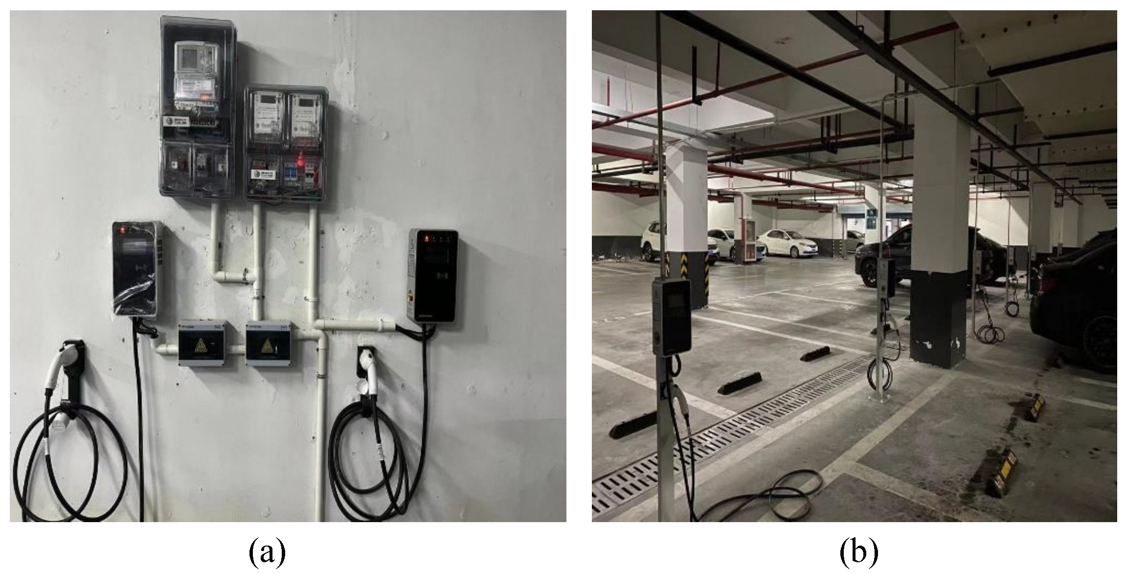
6.1. Pilot Project Description

The pilot project is located in Binjiang District, Hangzhou, China, which is an underground parking lot attached to a residential condominium building. The project is with a 700 kVA distribution, a total of 60 charging piles comprise the proposed OCC program. The fleet of EVs enrolled in the OCC is a mix of EVs and plug-in hybrid EVs, the maximum charging power rating ranges from 7.7 kW to 3.3 kW. Figure 9 demonstrates the developed smart meter prototype with OCC module installed. As can be seen from the picture, there is a pair of wires colored in red and black coming from the module; they are CC/CP wires as discussed previously in this paper. Figure 10 further illustrates the environment of the field test with the wall-mounted smart meter and charging piles installed and an overview of the parking lot.

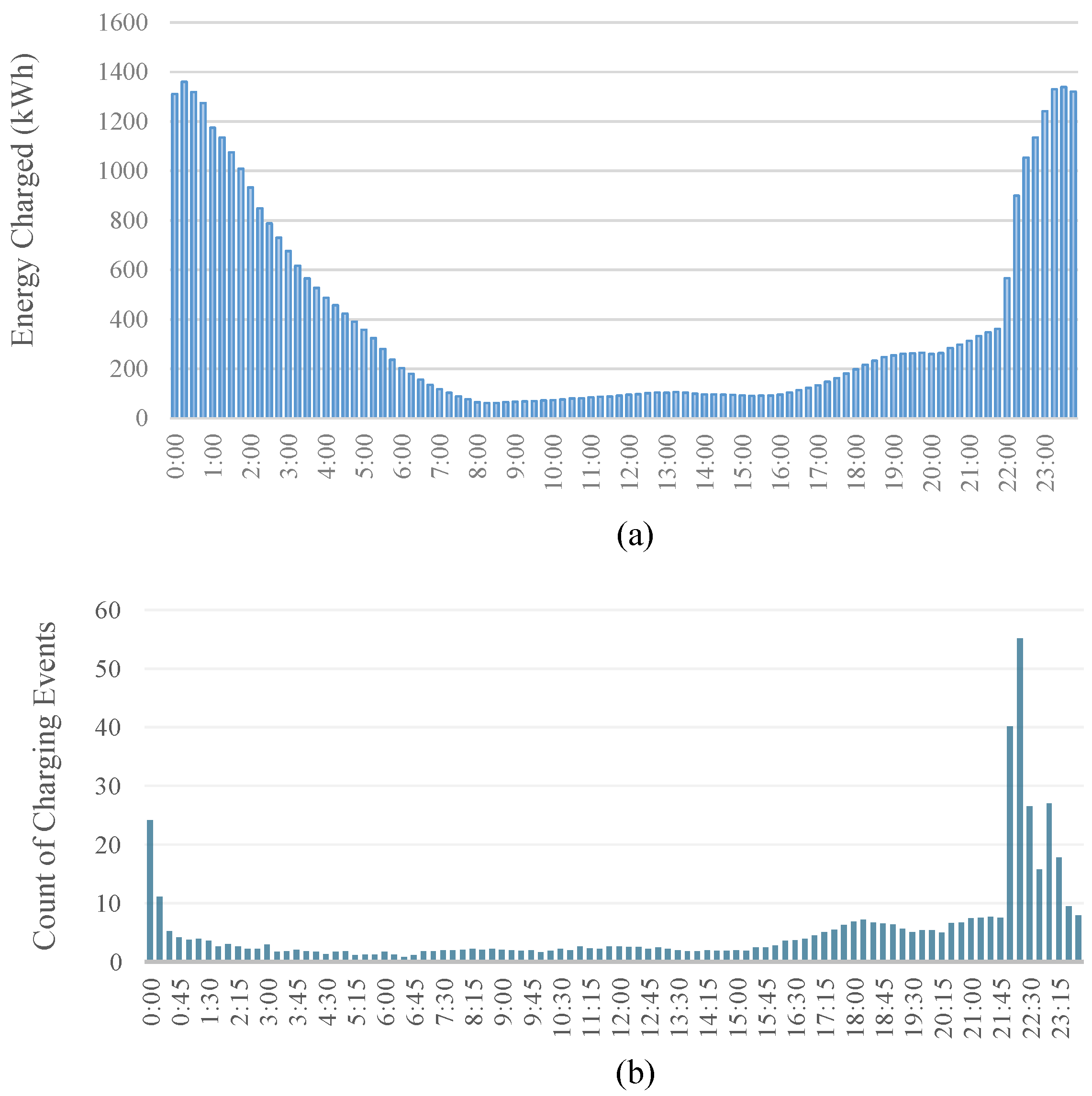
6.2. Historical Charging Data Analysis
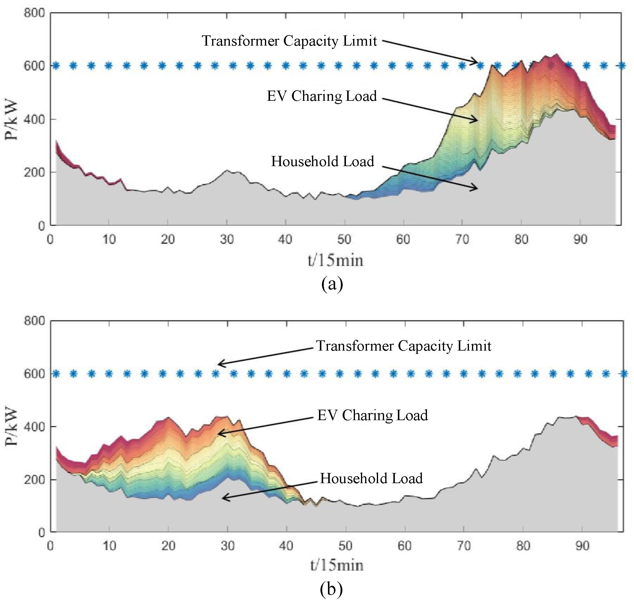
The charging data of the studied parking lot, spanning from July 2021 to April 2022, were analyzed to understand the user charging behavior. Figure 11 illustrates the accumulated charging energy and the count of charging events at different times of day. As we can observe from the figure, the peak period is found to be from 21:45 to 3:30. The charged energy in the peak period accounts for 65.39 % of the total daily charging energy, with 60.23 % of charging events highly concentrated during this peak period. This indicates that residential users’ charging activities are predominantly concentrated during nighttime peak hours, when the TOU rate is lower. Under the conditions of price guidance combined with unregulated charging, a new load peak is likely to occur at night (to be more precise, around 22:00), posing a threat to the transformer/feeder capacity in the residential area.

6.3. OCC Results

The proposed OCC scheme is verified in the field test on a typical weekday; the results are shown in Figure 12. Despite a significant decrease in total charging cost, we can observe that, without OCC, the load peak is already very close to the transformer’s capacity. However, with an orderly charging strategy, the load peak can be shifted to the early morning hours, thereby reducing the transformer’s loading rate. Therefore, orderly charging not only lowers users’ charging costs but also achieves peak shaving and valley filling, ensuring the safe operation of the distribution area transformer. Detailed comparative data without and with OCC are provided in Table 4, which further highlight the technical advantages of the proposed OCC approach.

7. Conclusions

In this work, a smart meter-based OCC for EV groups in residential area is proposed, in order to avoid overloading the distribution transformer. To achieve this goal, a smart meter-based distributed controller is designed based on a CC/CP communication scheme in the state-of-the-art charging standard. Based on the developed “cloud–meter–pile–vehicle” bidirectional communication interface, an event-driven OCC algorithm is developed, and then, deployed in the data hub (concentrator) of the AMI. The effectiveness of the proposed approach, including both hardware and software parts, is validated using a numerical case study and a practical field test in Hangzhou, China. Both results indicates promising advantages of the proposed approach in reducing the peak load of emerging EV charging demand by more than 30 % .

Author Contributions

Conceptualization, C.X. and G.G.; data curation, M.W. and Y.H.; formal analysis, X.X.; funding acquisition, C.X.; investigation, A.L. and Y.C.; methodology, A.L. and Y.C.; project administration, Y.C.; resources, X.X. and C.X.; software, M.W. and Y.H.; supervision, A.L. and G.G.; validation, M.W. and Y.H.; visualization, M.W. and Y.H.; writing—original draft, A.L. and G.G.; writing—review and editing, A.L. and G.G. All authors have read and agreed to the published version of the manuscript.

Funding

This research was funded by State Grid Zhejiang Electric Power Co., Ltd. under grant number 5211HZ22001V.

Data Availability Statement

The datasets presented in this article are not readily available because of confidentiality restrictions.

Acknowledgments

The authors would like to thank Geely Automobile Research Institute, Ningbo, China, for offering the engineering prototype vehicle with upgraded OBC firmware for the field test.

Conflicts of Interest

Ang Li, Yi Chen, Xinyu Xiang, and Chuanzi Xu are employees of the State Grid Hangzhou Power Supply Company. The paper reflects the views of the authors and not the company.

References

  1. Ayoade, I.A.; Longe, O.M. A Comprehensive Review on Smart Electromobility Charging Infrastructure. World Electr. Veh. J. 2024, 15, 286. [Google Scholar] [CrossRef]
  2. Development and Reform Commission of Zhejiang Province. Temporary Measures for the Construction, Operation, and Management of Electric Vehicle Charging Infrastructure in Zhejiang Province; Technical Report; Development and Reform Commission of Zhejiang Province: Hangzhou, China, 2023.
  3. Development and Reform Commission of Zhejiang Province. Zhejiang Province High-Quality Construction Electric Vehicle Infrastructure Special Action Plan; Technical Report; Development and Reform Commission of Zhejiang Province: Hangzhou, China, 2023.
  4. Powell, S.; Cezar, G.V.; Min, L.; Azevedo, I.M.L.; Rajagopal, R. Charging infrastructure access and operation to reduce the grid impacts of deep electric vehicle adoption. Nat. Energy 2022, 7, 932–945. [Google Scholar] [CrossRef]
  5. Aoun, A.; Adda, M.; Ilinca, A.; Ghandour, M.; Ibrahim, H. Dynamic Charging Optimization Algorithm for Electric Vehicles to Mitigate Grid Power Peaks. World Electr. Veh. J. 2024, 15, 324. [Google Scholar] [CrossRef]
  6. Xia, L.; Hong, X.; Sun, X.; Li, Q.; Wu, H.; Huo, Y.; Geng, G. Mitigation of Distribution Transformer Overloading with Rolling-Horizon Optimization of Vehicle-to-Grid Resource. In Proceedings of the 2024 3rd Conference on Fully Actuated System Theory and Applications (FASTA), Shenzhen, China, 10–12 May 2024; pp. 1123–1128. [Google Scholar] [CrossRef]
  7. Tang, W.; Bi, S.; Zhang, Y.J. Online Charging Scheduling Algorithms of Electric Vehicles in Smart Grid: An Overview. IEEE Commun. Mag. 2016, 54, 76–83. [Google Scholar] [CrossRef]
  8. Clement-Nyns, K.; Haesen, E.; Driesen, J. The Impact of Charging Plug-In Hybrid Electric Vehicles on a Residential Distribution Grid. IEEE Trans. Power Syst. 2010, 25, 371–380. [Google Scholar] [CrossRef]
  9. Crozier, C.; Morstyn, T.; Deakin, M.; McCulloch, M. The case for Bi-directional charging of electric vehicles in low voltage distribution networks. Appl. Energy 2020, 259, 114214. [Google Scholar] [CrossRef]
  10. Chen, S.; Lang, H.; Wan, M.; Du, J.; Bao, F.; Geng, G. Operational Flexibility Enhancement with Aggregated Electric Vehicles based on Virtual Energy Storage Model. In Proceedings of the 2024 3rd Conference on Fully Actuated System Theory and Applications (FASTA), Shenzhen, China, 10–12 May 2024; pp. 110–115. [Google Scholar] [CrossRef]
  11. Weng, Z.; Zhou, J.; Song, X.; Jing, L. Research on Orderly Charging Strategy for Electric Vehicles Based on Electricity Price Guidance and Reliability Evaluation of Microgrid. Electronics 2023, 12, 4876. [Google Scholar] [CrossRef]
  12. Wang, F.; Xiang, B.; Li, K.; Ge, X.; Lu, H.; Lai, J.; Dehghanian, P. Smart Households’ Aggregated Capacity Forecasting for Load Aggregators Under Incentive-Based Demand Response Programs. IEEE Trans. Ind. Appl. 2020, 56, 1086–1097. [Google Scholar] [CrossRef]
  13. Moon, S.; Lee, J.W. Multi-Residential Demand Response Scheduling With Multi-Class Appliances in Smart Grid. IEEE Trans. Smart Grid 2018, 9, 2518–2528. [Google Scholar] [CrossRef]
  14. Shafiq, S.; Al-Awami, A.T. An Autonomous Charge Controller for Electric Vehicles Using Online Sensitivity Estimation. IEEE Trans. Ind. Appl. 2020, 56, 22–33. [Google Scholar] [CrossRef]
  15. Lee, Z.J.; Sharma, S.; Johansson, D.; Low, S.H. ACN-Sim: An Open-Source Simulator for Data-Driven Electric Vehicle Charging Research. IEEE Trans. Smart Grid 2021, 12, 5113–5123. [Google Scholar] [CrossRef]
  16. Zhejiang Provincial Energy Bureau. 2024 Zhejiang Province Peak Summer Power Demand-Side Management Implementation Plan; Technical Report; Zhejiang Provincial Energy Bureau: Hangzhou, China, 2024.
  17. Yu, H.; Xu, C.; Wang, W.; Geng, G.; Jiang, Q. Communication-Free Distributed Charging Control for Electric Vehicle Group. IEEE Trans. Smart Grid 2024, 15, 3028–3039. [Google Scholar] [CrossRef]
  18. Orlando, M.; Estebsari, A.; Pons, E.; Pau, M.; Quer, S.; Poncino, M.; Bottaccioli, L.; Patti, E. A Smart Meter Infrastructure for Smart Grid IoT Applications. IEEE Internet Things J. 2022, 9, 12529–12541. [Google Scholar] [CrossRef]
  19. Sun, Q.; Li, H.; Ma, Z.; Wang, C.; Campillo, J.; Zhang, Q.; Wallin, F.; Guo, J. A Comprehensive Review of Smart Energy Meters in Intelligent Energy Networks. IEEE Internet Things J. 2016, 3, 464–479. [Google Scholar] [CrossRef]
  20. NB/T 33002-2010; Specification for Electric Vehicle AC Charging Point. China Electricity Council (CEC): Beijing, China, 2010.
  21. Wikipedia Contributors. GB/T Charging Standard—Wikipedia, The Free Encyclopedia. 2024. Available online: https://en.wikipedia.org/wiki/GB/T_charging_standard (accessed on 3 August 2024).
  22. Peng, C.; Luo, R.; Wang, X. Research on a New Generation of Smart Meter Technology Supports Ubiquitous Power Internet of Things. Electr. Meas. Instrum. 2019, 56, 137–142. [Google Scholar] [CrossRef]
  23. DL/T 1490-2015; Functional Specification of Smart Meters. China Electricity Council (CEC): Beijing, China, 2015.
  24. Al-Ogaili, A.S.; Tengku Hashim, T.J.; Rahmat, N.A.; Ramasamy, A.K.; Marsadek, M.B.; Faisal, M.; Hannan, M.A. Review on Scheduling, Clustering, and Forecasting Strategies for Controlling Electric Vehicle Charging: Challenges and Recommendations. IEEE Access 2019, 7, 128353–128371. [Google Scholar] [CrossRef]
  25. Chen, Y.; Pang, B.; Xiang, X.; Lu, T.; Xia, T.; Geng, G. Probabilistic Forecasting of Electric Vehicle Charging Load Using Composite Quantile Regression LSTM. In Proceedings of the 2023 IEEE/IAS Industrial and Commercial Power System Asia (I&CPS Asia), Chongqing, China, 7–9 July 2023; pp. 984–989. [Google Scholar] [CrossRef]
  26. Ji, Y.; Yang, Y.; Geng, G.; Jiang, Q. Online Refinement of Day-Ahead Forecasting using Intraday Data for Campus-Level Load. IET Gener. Transm. Distrib. 2022, 16, 1189–1200. [Google Scholar] [CrossRef]
Figure 1. Illustrative problem statement of the proposed OCC approach.
Wevj 15 00449 g001
Figure 2. Charging standard following GB/T 20234 [20]. (a) Charging socket outlet and plug; (b) definition of pinouts.
Wevj 15 00449 g002
Figure 3. Voltage oscillator on CC/CP wires.
Wevj 15 00449 g003
Figure 4. Diagram of CC/CP-based communication interface between EV and external controller.
Wevj 15 00449 g004
Figure 5. Diagram of modular smart meter standardized by SGCC.
Wevj 15 00449 g005
Figure 6. Interactive protocol between EV and AMI.
Wevj 15 00449 g006
Figure 7. Neural network structure of the prediction model for EV charging load.
Wevj 15 00449 g007
Figure 8. Operational results of the residential area in the numerical case study. (a) Power curves without OCC; (b) power curves with the proposed OCC.
Wevj 15 00449 g008
Figure 9. Smart meter prototype with the developed control module installed.
Wevj 15 00449 g009
Figure 10. Field test at an underground parking lot in Hangzhou, China. (a) Smart meter installations with OCC module embedded and connected to charging piles. (b) Overview of the parking lot with OCC-enabled charging piles.
Wevj 15 00449 g010
Figure 11. Charging data analysis results for the parking lot in Hangzhou, China. (a) Accumulated charging energy at different times of day; (b) accumulated count of charging events at different times of day.
Wevj 15 00449 g011
Figure 12. Operation results of the parking lot in Hangzhou, China.
Wevj 15 00449 g012
Table 1. Relationship between duty cycle D and corresponding commands.
PWM Duty Cycle DMaximum Charging Current I max / A
D = 0 % Charging pile not ready
D = 5 % Digital communication establishing
10 % D 85 % I max = D × 100 × 0.6
85 % < D 90 % I max = ( D × 100 64 ) × 2.5 & I max 63
90 % < D 97 % Reserved
D = 100 % Forbidden
Table 2. TOU tariff rate for residential customers in Hangzhou, China.
Time PeriodRate (CNY/kWh)
Peak (8:00–22:00) 0.568
Off peak (22:00–8:00) 0.288
Table 3. Numerical comparison between operational results without and with OCC.
Operational ResultsWithout OCCWith OCC
Peak load (kW) 644.1 438.0
Peak-to-valley (kW) 547.6 340.9
Total charging cost (CNY) 1114.9 728.2
Table 4. Comparison between operational results without and with OCC in the field test.
Field Test ResultsWithout OCCWith OCC
Peak load (kW) 686.1 460.8
Peak-to-valley (kW) 456.12 324.8
Total charging cost (CNY) 1673.2 1039.8
Disclaimer/Publisher’s Note: The statements, opinions and data contained in all publications are solely those of the individual author(s) and contributor(s) and not of MDPI and/or the editor(s). MDPI and/or the editor(s) disclaim responsibility for any injury to people or property resulting from any ideas, methods, instructions or products referred to in the content.

