
Two-Stage Multiple-Vector Model Predictive Control for Multiple-Phase Electric-Drive-Reconstructed Power Management for Solar-Powered Vehicles


Abstract
:1. Introduction
2. Operation Principle of EDROC
2.1. Topology
2.2. Model of Six-Phase Symmetrical PMSM
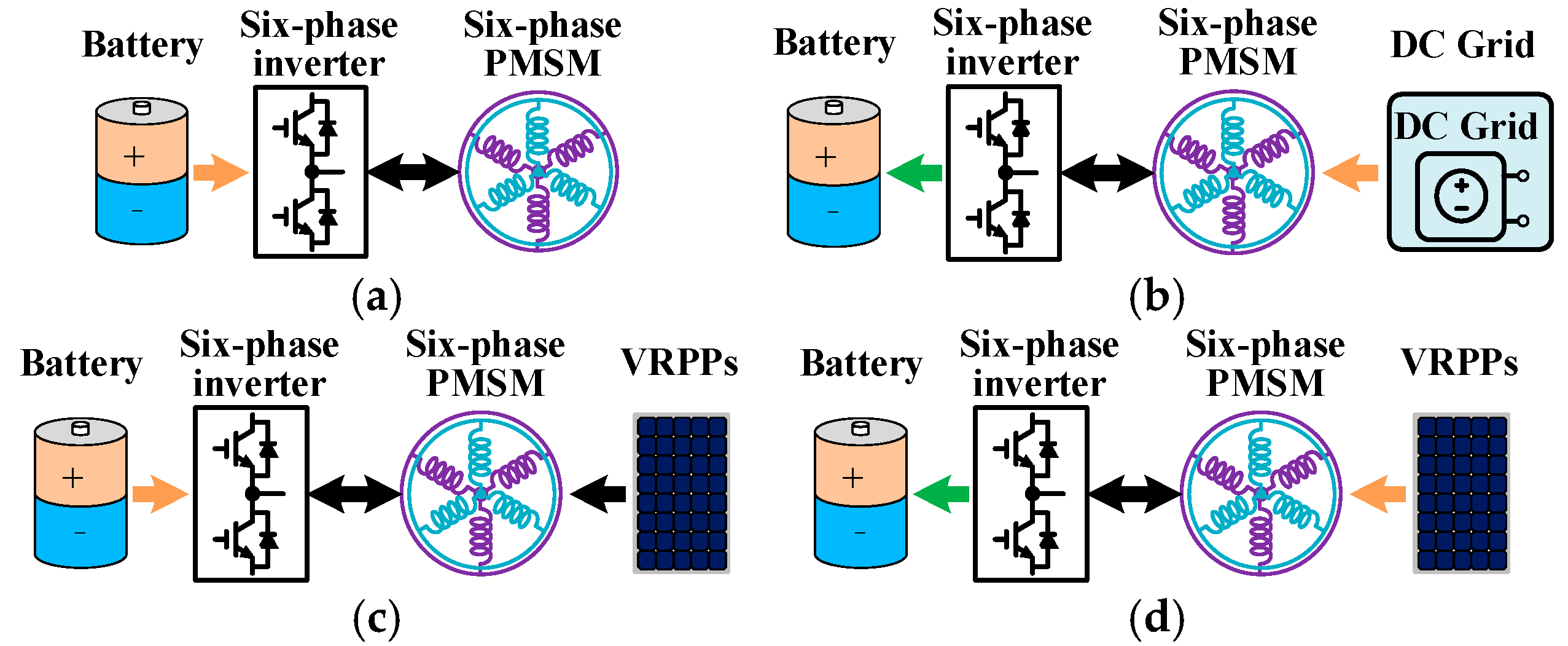
2.3. Analysis of Operation Principle
3. Proposed MPCC of EDROC
3.1. Traditional MPCC
3.2. Designer of the Proposed MPCC
3.3. Implementation of Proposed MPCC
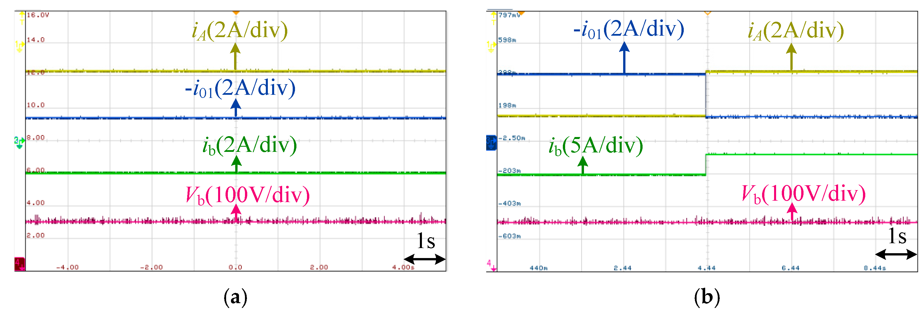
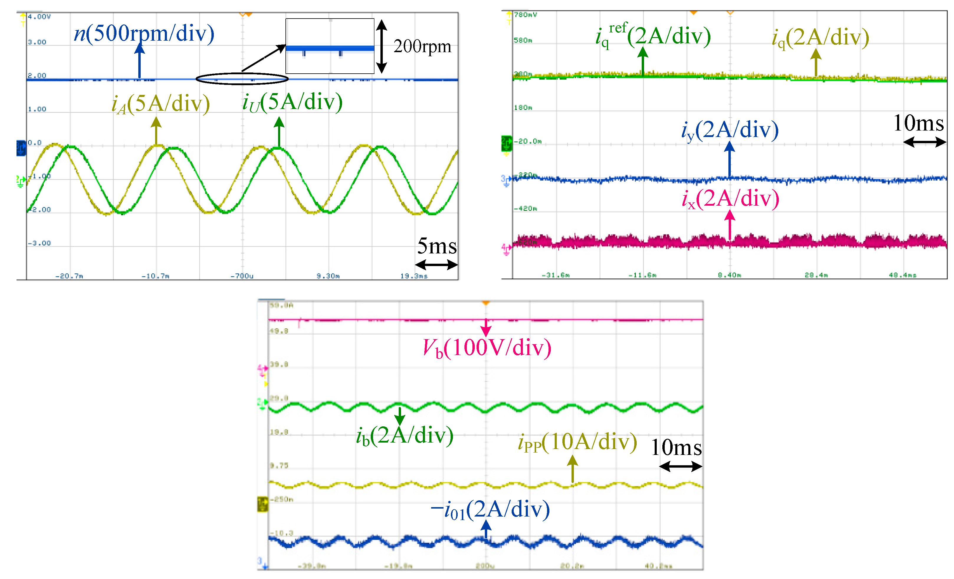
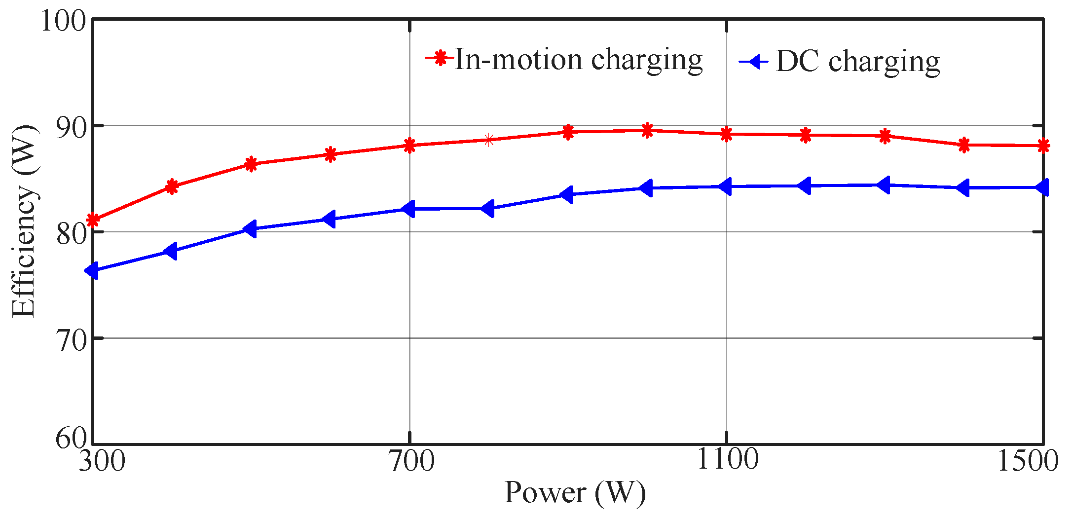
4. Experimental Results
5. Conclusions
Author Contributions
Funding
Data Availability Statement
Conflicts of Interest
References
- Acharige, S.; Haque, M.; Arif, M.; Hosseinzadeh, N. Review of electric vehicle charging technologies, standards, architectures, and converter configurations. IEEE Access 2023, 11, 41218–41255. [Google Scholar] [CrossRef]
- Yao, M.; Da, D.; Lu, X.; Wang, Y. A review of capacity allocation and control strategies for electric vehicle charging stations with integrated photovoltaic and energy storage systems. World Electr. Veh. J. 2024, 15, 101. [Google Scholar] [CrossRef]
- Wouters, H.; Martinez, W. Bidirectional onboard chargers for electric vehicles: State-of-the-art and future trends. IEEE Trans. Power Electron. 2024, 39, 693–716. [Google Scholar] [CrossRef]
- Sharma, S.; Aware, M.V.; Bhowate, A. Integrated battery charger for EV by using three-phase induction motor stator windings as filter. IEEE Trans. Transp. Electrif. 2020, 6, 83–94. [Google Scholar] [CrossRef]
- Ullah, Z.; Metwly, M.Y.; Hemeida, A.; Abdel-Khalik, A.S.; He, J.; Ahmed, S. Demagnetization and thermal analysis of six-phase permanent magnet motor-based integrated onboard EV charging. IEEE Trans. Transp. Electrif. 2014, 10, 3334–3348. [Google Scholar] [CrossRef]
- Xiao, Y.; Liu, C. A study of rotational movement and charging torque of reconfigured on-board charger. IEEE Trans. Power Electron. 2020, 35, 10720–10728. [Google Scholar] [CrossRef]
- Xiao, Y.; Liu, C.; Yu, F. An integrated on-board EV charger with safe charging operation for three-phase IPM motor. IEEE Trans. Ind. Electron. 2019, 66, 7551–7560. [Google Scholar] [CrossRef]
- Salem, A.; Narimani, M. A review on multiphase drives for automotive traction applications. IEEE Trans. Transp. Electrif. 2019, 5, 1329–1348. [Google Scholar] [CrossRef]
- Tong, M.; Cheng, M.; Wang, S.; Hua, W. An on-board two-stage integrated fast battery charger for EVs based on a five-phase hybrid-excitation flux-switching machine. IEEE Trans. Ind. Electron. 2021, 68, 1780–1790. [Google Scholar] [CrossRef]
- Xiao, Y.; Liu, C.; Yu, F. An effective charging-torque elimination method for six-phase integrated on-board ev chargers. IEEE Trans. Power Electron. 2020, 35, 2776–2786. [Google Scholar] [CrossRef]
- He, S.; Xu, Z.; Chen, M. General derivation law with torque-free achieving of integral on-board charger on compact powertrains. IEEE Trans. Ind. Electron. 2021, 68, 1791–1802. [Google Scholar] [CrossRef]
- Mulhall, P.; Lukic, S.; Wirasingha, S. Solar-assisted electric auto rickshaw three-wheeler. IEEE Trans. Veh. Technol. 2010, 59, 2298–2307. [Google Scholar] [CrossRef]
- Gopalasami, R.; Chokkalingam, B. A photovoltaic-powered modified multiport converter for an EV charger with bidirectional and grid connected capability assist PV2V, G2V, and V2G. World Electr. Veh. J. 2024, 15, 31. [Google Scholar] [CrossRef]
- Viana, C.; Lehn, P. A drivetrain integrated DC fast charger with buck and boost functionality and simultaneous drive/charge capability. IEEE Trans. Transp. Electrif. 2019, 5, 903–911. [Google Scholar] [CrossRef]
- Yu, F.; Zhu, Z.; Liu, X.; Zhang, Z. Electric-drive-reconstructed onboard charger for solar-powered electric vehicles incorporating six-phase machine. IEEE Trans. Power Electron. 2022, 37, 6544–6555. [Google Scholar] [CrossRef]
- Yu, F.; Yin, Q.; Zhu, Z.; Cheng, X. A multienergy interface electric-drive- reconstructed onboard charger for EVs with integrated control strategy. IEEE Trans. Power Electron. 2024, 39, 4050–4061. [Google Scholar] [CrossRef]
- Taha, R.A.; Abdel-Azim, W.E.; Shawier, A.; Metwly, M.Y.; Abdel-Khalik, A.S.; Hamad, M.S.; Hamdy, R.A.; Gadoue, S.; Ahmed, S. Single-phase charging of six-phase integrated on-board battery charger using predictive current control. IEEE Trans. Transp. Electrif. 2024, 10, 540–552. [Google Scholar] [CrossRef]
- Karneddi, H.; Ronanki, D.; Rodriguez, J. Universal integrated onboard charger with model predictive current control for plug-in EV charging. IEEE Trans. Power Electron. 2024, 1–6. [Google Scholar] [CrossRef]
- Habib, A.; Shawier, A.; Abdel-Majeed, M.S.; Abdel-Khalik, A.S.; Hamad, M.S.; Hamdy, R.A.; Ahmed, S. Predictive current control of six-phase IM-based nonisolated integrated on-board battery charger under different winding configurations. IEEE Trans. Power Electron. 2022, 37, 8345–8358. [Google Scholar] [CrossRef]
- Bhule, D.; Kaarthik, R.S. A model predictive control scheme for a single-phase integrated battery charger with active power decoupling for EV application. IEEE Trans. Power Electron. 2024, 39, 4117–4126. [Google Scholar] [CrossRef]


| Voltage Vectors | 01-Axis Values | Voltage Vectors | 01-Axis Values |
|---|---|---|---|
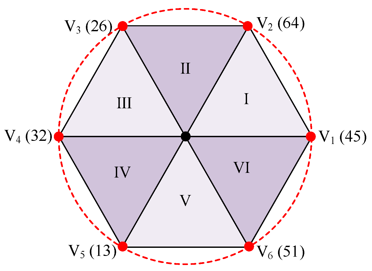
| V1 (45) | −0.167 Vb | V5 (13) | −0.167 Vb |
| V2 (64) | 0.167 Vb | V6 (51) | 0.167 Vb |
| V3 (26) | −0.167 Vb | V7 (70) | 0.5 Vb |
| V4 (32) | 0.167 Vb | V8 (07) | −0.5 Vb |
| Parameters | Values |
|---|---|
| Rated power | 2.0 kW |
| Rated speed | 2000 rpm |
| Number of pole pairs | 5 |
| Direct axis inductance | 5.56 mH |
| Quadrature axis inductance | 7 mH |
| 0-axis inductance | 0.125 mH |
| Phase resistance | 0.3 Ω |
| Stator-PM magnetic flux | 0.042 Wb |
Disclaimer/Publisher’s Note: The statements, opinions and data contained in all publications are solely those of the individual author(s) and contributor(s) and not of MDPI and/or the editor(s). MDPI and/or the editor(s) disclaim responsibility for any injury to people or property resulting from any ideas, methods, instructions or products referred to in the content. |
© 2024 by the authors. Published by MDPI on behalf of the World Electric Vehicle Association. Licensee MDPI, Basel, Switzerland. This article is an open access article distributed under the terms and conditions of the Creative Commons Attribution (CC BY) license (https://creativecommons.org/licenses/by/4.0/).
Share and Cite
Zhu, Q.; Zhang, Z.; Zhu, Z. Two-Stage Multiple-Vector Model Predictive Control for Multiple-Phase Electric-Drive-Reconstructed Power Management for Solar-Powered Vehicles. World Electr. Veh. J. 2024, 15, 466. https://doi.org/10.3390/wevj15100466
Zhu Q, Zhang Z, Zhu Z. Two-Stage Multiple-Vector Model Predictive Control for Multiple-Phase Electric-Drive-Reconstructed Power Management for Solar-Powered Vehicles. World Electric Vehicle Journal. 2024; 15(10):466. https://doi.org/10.3390/wevj15100466
Chicago/Turabian StyleZhu, Qingyun, Zhen Zhang, and Zhihao Zhu. 2024. "Two-Stage Multiple-Vector Model Predictive Control for Multiple-Phase Electric-Drive-Reconstructed Power Management for Solar-Powered Vehicles" World Electric Vehicle Journal 15, no. 10: 466. https://doi.org/10.3390/wevj15100466
APA StyleZhu, Q., Zhang, Z., & Zhu, Z. (2024). Two-Stage Multiple-Vector Model Predictive Control for Multiple-Phase Electric-Drive-Reconstructed Power Management for Solar-Powered Vehicles. World Electric Vehicle Journal, 15(10), 466. https://doi.org/10.3390/wevj15100466