Article

A Simplified 4-DOF Dynamic Model of a Series-Parallel Hybrid Electric Vehicle

1
State Key Laboratory of Engines, Tianjin University, Tianjin 300350, China
2
Chery Jetour Automobile Co., Ltd., Wuhu 241002, China
3
KUNTYE Vehicle System Co., Ltd., Changzhou 213011, China
*
Author to whom correspondence should be addressed.
World Electr. Veh. J. 2024, 15(9), 390; https://doi.org/10.3390/wevj15090390
Submission received: 13 May 2024 / Revised: 4 June 2024 / Accepted: 27 June 2024 / Published: 28 August 2024
(This article belongs to the Special Issue Dynamics, Control and Simulation of Electrified Vehicles)

Abstract

:
To research the dynamic response of a new type of dedicated transmission for a hybrid electric vehicle, a detailed dynamics model should be built. However, a model with too many degrees of freedom has a negative effect on controller design, which means the detailed model should be simplified. In this paper, two dynamic models are established. One is an original and detailed powertrain dynamics model (ODPDM), which can capture the transient response, and it is validated that the ODPDM can be used to accurately describe the real vehicle in some specific operating conditions. The other is a simplified torsional vibration dynamics model to study the torsional vibration characteristics of the hybrid electric vehicle. Compared with the full-order model, which is based on the ODPDM, the simplified model has a very similar vibration in low frequency. This study provides a basis for further vibration control of the hybrid powertrain during the process of a driving-mode switch.

1. Introduction

1.1. Motivations and Technical Challenges

Hybrid electric vehicles (HEVs) are increasingly standing out in the automotive market since they are highly effective in reducing the fuel consumption and CO2 emissions of conventional vehicles [1,2,3]. Consequently, the hybridization of conventional vehicles presents a variety of potential avenues for enhancing the vehicle’s fuel efficiency [4]. Hardware-in-the-loop (HiL) tests are an important method in vehicle engineering. They cost less, have higher efficiency, and lower risk than real vehicle tests [5,6]. However, the HiL test is based on a model instead of a real vehicle, which means establishing a stable model that can accurately describe the real dynamic response of the real vehicle is necessary. To build a precise model to imitate a real HEV, it’s obvious that the more details considered and set in the model, the more similarity will be found between the model and the real HEV. Nevertheless, a model that has too many details and parameters will make the control system extremely hard to design. Generally speaking, the less degree of freedom (DOF) is considered, the easier it is to design and build a control program. This paradox requires building an accurate model first and then simplifying it to a model, which has less DOF to make the controller design simplified and has a similar reaction to the accurate model.

1.2. Literature Review

Lots of researchers have completed work to establish accurate models of vehicles. Walker et al. developed a mathematical model and multi-body dynamic model of an electric vehicle powertrain system and integrated them with a hydraulic clutch control system model, then did simulation and experimental studies of the shift transient behavior based on the model [7,8,9]. Shin et al. focus on friction linings and present a control-oriented modeling method for wet clutch friction that considers thermal dynamics. They use 184 experimental data sets to validate the model’s accuracy, and it can be used for model-based control [10]. Wang et al. investigate the shift control and the gearshift transient response of a new spring-based synchronizer and build a dynamics model of a two-speed AMT in an EV equipped with the spring-based synchronizer in AMESim software. The simulation of the dynamics model shows that compared with the traditional synchronizer, the spring-based synchronizer reduces engaging time and vehicle jerk [11]. Zhang et al. proposed a novel planetary gear set-based flywheel hybrid electric powertrain, which included an internal combustion engine, a planetary gear set that integrated a control motor, and an energy storage flywheel. By using the lever analogy method, they modeled and analyzed the powertrain and concluded that the vehicle equipped with PGS-FHEP has better performance on fuel economy and acceleration capability compared with the traditional manual transmission vehicle [12]. Ouyang et al. developed a dynamic model of an electro-hydraulic actuator for heavy-duty vehicles and adopted the artificial bee colony (ABC) algorithm to optimize the structural parameters to improve ride comfort and fuel economy [13]. Mo et al. built a vertical dynamic model of a new electric vehicle considering the powertrain and used it in a 10-DOF dynamic model. Compared with the traditional dynamic model, the new model can indicate vertical vibration more reliably [14]. Park et al. developed a model of the entire powertrain to describe dynamic characters in the mechanical and electrical systems of an electric vehicle in MATLAB [15]. Yakhshilikova et al. built a dynamic model of a P2 mild HEV considering engine inertia and developed a controller based on an equivalent consumption minimization strategy. The result shows the controller reduces the engine operation during high inertial torque transient phases and decreases CO2 emissions [16].
A lumped mass model, which means establishing a simplified model of the main part in the powertrain by using simple masses with springs and dampers between them, is a common way to analyze the torsional vibration characteristics of the vehicle in low frequency and control it. Walker et al. developed 15-DOF and 4-DOF lumped parameter models for a powertrain system equipped with a dual-clutch transmission to analyze transient shift responses. The higher-order model was capable of characterizing the vibration characteristics of the powertrain system with greater precision, whereas the lower-order model neglected certain essential dynamic responses. However, the latter reduced computational demand, making it more suitable for control application studies [17]. Zhang et al. established a mathematical model for a power-split hybrid transmission system based on Newton’s second law and Lagrange equations. Numerical calculations were performed using MATLAB, and a corresponding dynamical model was developed in the multibody dynamic software ADAMS. Both approaches yielded the natural frequencies and mode shapes of the hybrid transmission system, showing notable consistency between the results [18]. Tang et al. proposed a novel three-mass simplified torsional vibration dynamic model based on previous research, which is used to guide the vibration control of a hybrid powertrain during engine start/stop processes. Compared with the previous high-order model with 16 degrees of freedom, this model can accurately describe the low-frequency vibration characteristics of hybrid transmission systems [19]. Morandin et al. built a 3-DOF lumped mass model of a series-parallel HEV and designed an active damping controller for it. The conclusion indicates that the torsional vibration of the powertrain is lower and the vehicle runs smoother [20].

1.3. Original Contributions

Two original contributions in this paper show our work is different from other former researchers.
Firstly, an original and detailed powertrain dynamics model of a new type of dedicated transmission for a hybrid electric vehicle is established. It has been proven that ODPDM can replace the real vehicle in longitude dynamics study.
Secondly, a new method to simplify the full-order model into the low-freedom model is proposed. The method has been used to simplify the 16-DOF full-order model, which is based on the ODPDM, into a 4-DOF model, and the result shows that the 4-DOF model has a very similar vibration as the 16-DOF model in low frequency.

1.4. Outline of Paper

The structure of this paper is organized as follows. Section 2 elucidates the formation of the powertrain, establishes the ODPDM, and compares it with a real HEV in longitudinal dynamics. The 16-DOF full-order model of the vehicle is described in Section 3. In Section 4, the simplified torsional vibration dynamics model is expounded, together with comparative outcomes. Conclusions are drawn in Section 5.

2. Description of the Powertrain and the Longitudinal Dynamic Model

The powertrain of the series-parallel HEV, which is studied in this paper, contains an engine (Eng), clutch (C1), synchronizer with first gear (G1) and second gear (G2), P2 electric motor EM1, P3 electric motor EM2, reducer, differential, and half shafts, shown as Figure 1. If the clutch C1 is engaged and the synchronizer is in the neutral position, the system is in series mode. At this time, the engine drives the EM1 to generate electricity to charge the battery, and the EM2 drives the entire system separately. If the clutch C1 is engaged and the synchronizer is in the G1 position or G2 position, the system is in parallel mode. At this time, the Eng, EM1, and EM2 simultaneously output power, providing driving force for the entire vehicle through the main reducer and differential. If the clutch C1 does not engage and the Eng does not work, the system is in electric drive mode. At this time, if the synchronizer is in the neutral position, the EM1 does not work, and e EM2 provides the driving force for the entire vehicle only. If the synchronizer is in the G1 or G2 position, the EM1 and EM2 work simultaneously to provide the driving force for the entire vehicle.
When the clutch C1 is engaged and the synchronizer is in the neutral position, the torque from the Eng is transmitted to the EM1 through the clutch C1. When the clutch C1 is engaged and the synchronizer is in the G1 position or G2 position, the torque from the Eng is transmitted to the left and right half shafts through the clutch C1, synchronizer G1 or G2, reducer, and differential, and finally acts on the wheels. When the synchronizer is in the G1 or G2 position, the torque of the EM1 is transmitted to the left and right half shafts, passes through three gears, the synchronizer G1 or G2, reducer, and differential, and finally acts on the wheels. The torque of the EM2 is transmitted to the left and right half shafts, passes through the reducer and differential, and finally acts on the wheels.
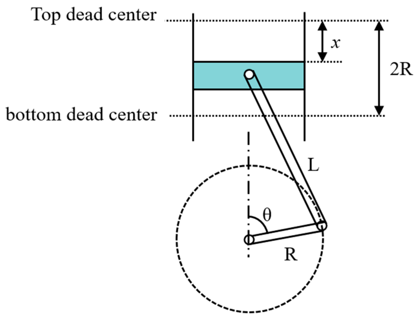
The engine is one of the main vibration excitation sources of the powertrain. The torque that the engine outputs consists of two parts: one is gas torque exported from the gas that is burnt in the cylinder, and the other is inertial torque output during the reciprocating motion of the piston [21]. It is proved that the maximum inertial torque is much greater than the average torque that the engine outputs. The cylinder is shown in Figure 2, where R is the radius of the crank, L is the length of the connecting rod, x is piston displacement, and θ is the crank angle. The relation between x and θ is shown in Equation (1):
x = L + R R c o s θ L 1 k 2 s i n 2 θ
k = R L
Using the McLaughlin expansion of Equation (1) and ignoring high-order terms results in the following:
x = L + R R c o s θ L 1 1 2 k s i n θ 2 = R 1 + k 4 + c o s θ k 4 c o s 2 θ
The second derivative of x is acceleration. The force acting on the piston can be delivered to two parts: one is perpendicular to the crank and the other along the crank. Only the one that is perpendicular to the crank is called the inertial torque and it is shown in Equation (4), where m is the equivalent mass of the piston, x ¨ is the acceleration of the piston, and ω is the rotary speed of the crank.
T j = m x ¨ = m R 2 ω 2 cos ω t + k cos 2 ω t sin θ + k 2 sin 2 θ = m R 2 ω 2 1 4 k sin ω t 1 2 sin 2 ω t 3 4 k sin 3 ω t k 2 4 sin 4 ω t
The engine in this paper is a four-cylinder in-line engine, which working order is 1-3-4-2. The phase of the second and third cylinders is 180 degrees slower than the first and fourth cylinders, shown in Equation (5):
T j , 1 = T j , 4 = T j ω t T j , 2 = T j , 3 = T j ω t + π
The gas torque can be described as the mean model, which is shown in the external characteristic curve of the engine.
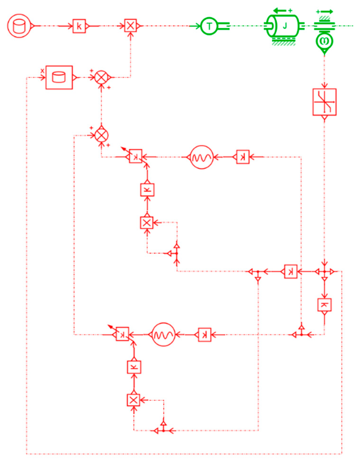
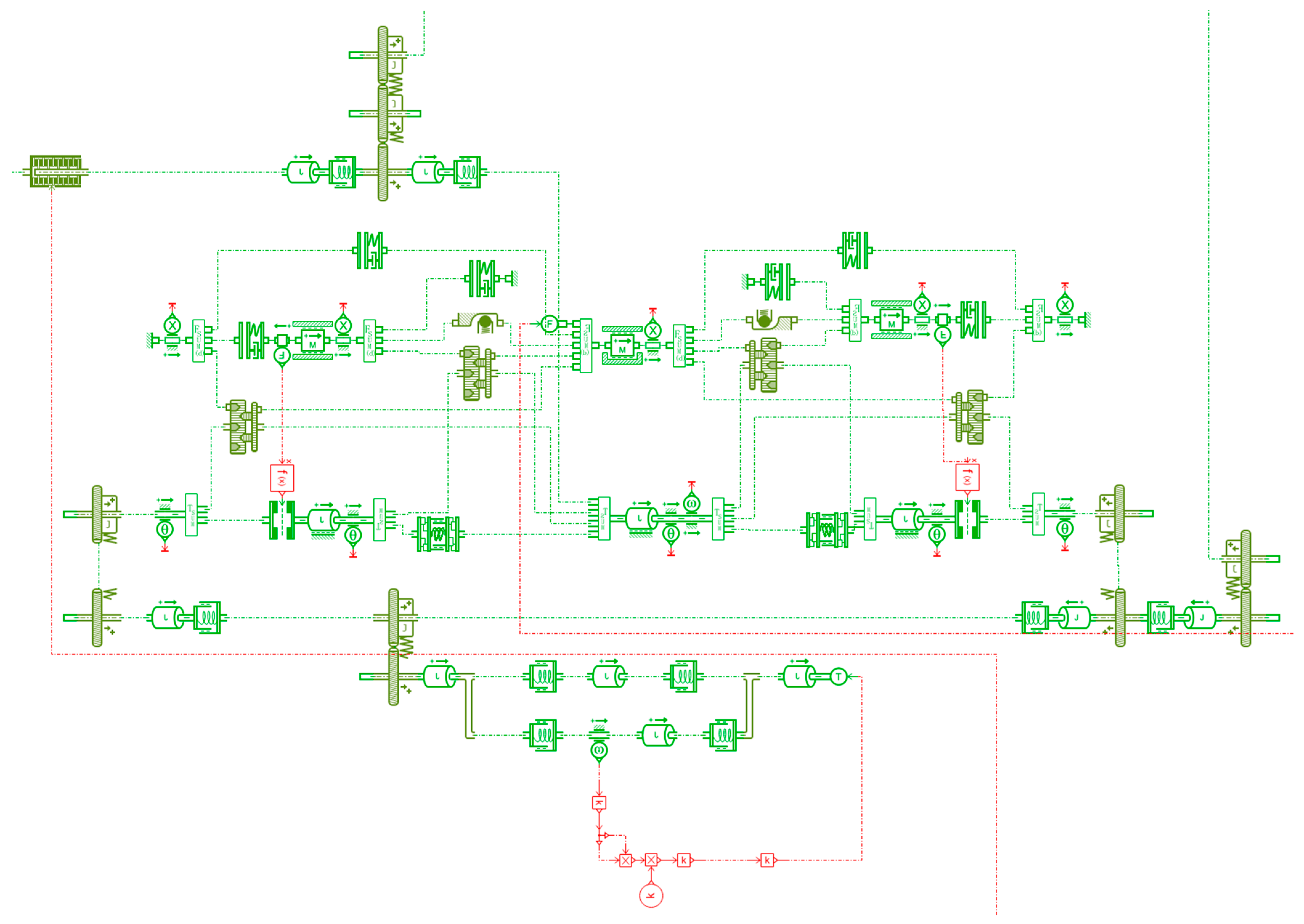
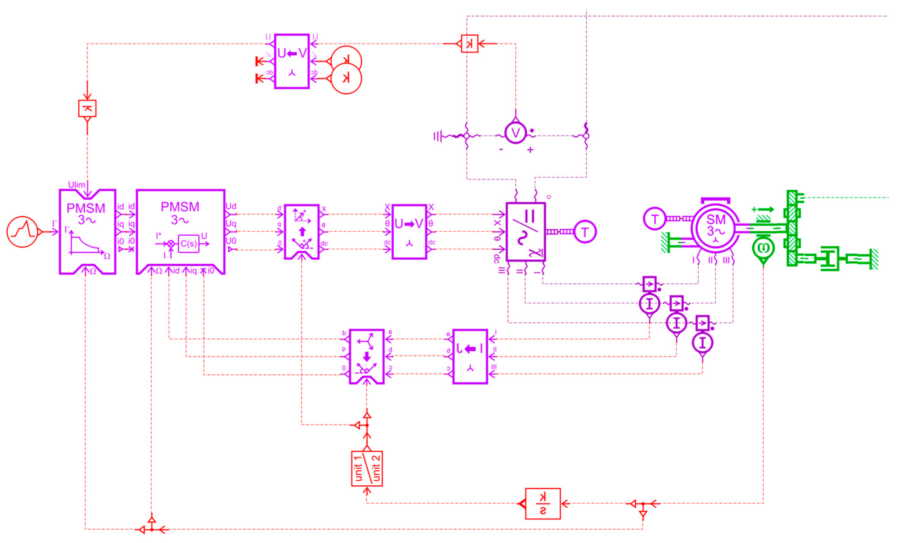
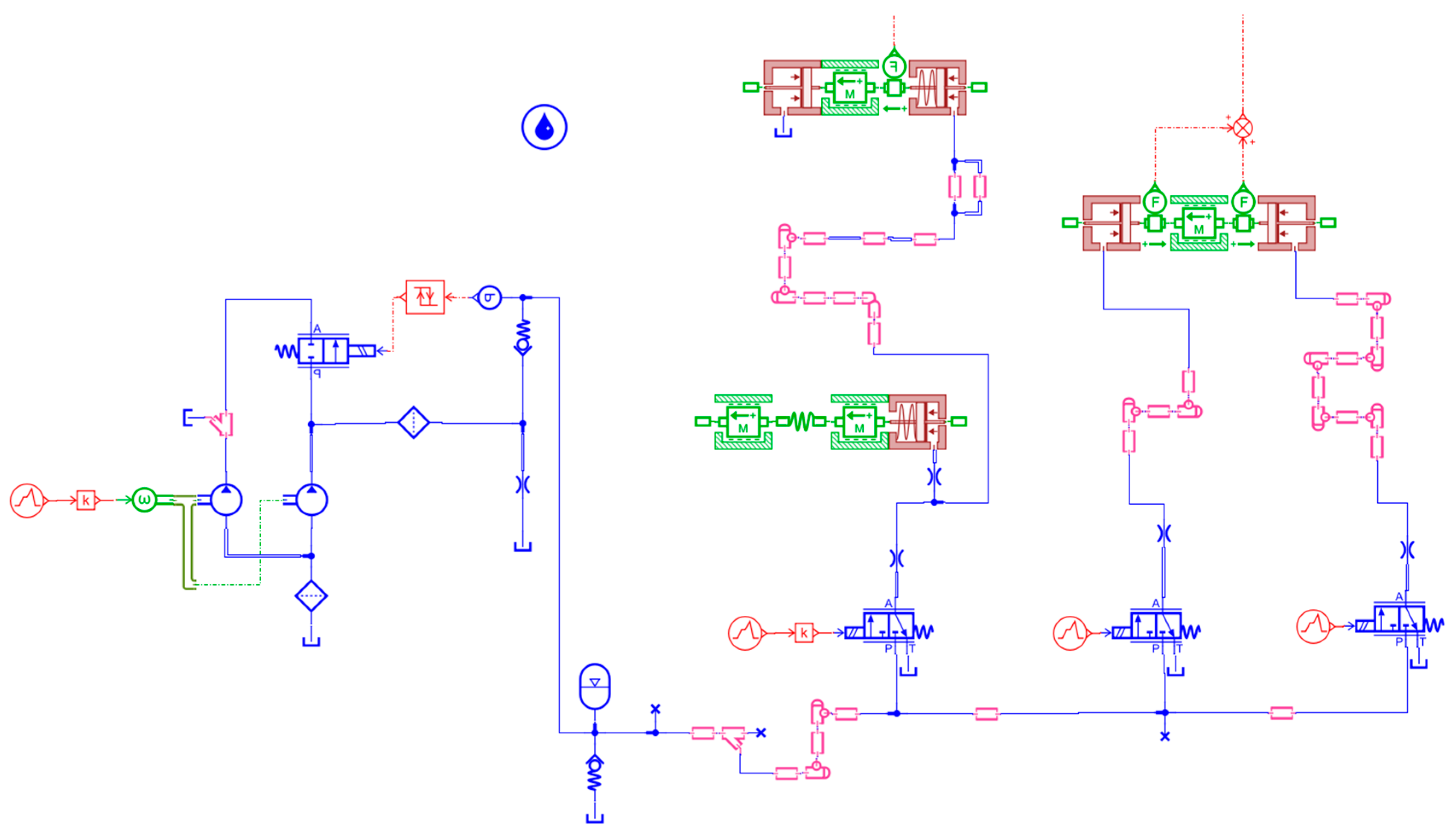
Based on these equations and AMEsim software, the longitudinal dynamic model is shown in Figure 3, Figure 4, Figure 5 and Figure 6. Figure 3 shows the engine model that is combined with Equation (5) and the gas torque. Figure 4 shows the transmission system of the HEV, considering the clearance of the synchronizer, the meshing stiffness, and the damping of the gears as well as the equivalent of the translational mass of the vehicle body to the moment of inertia. The engine model in Figure 3 and the powertrain model in Figure 4 are connected by the wet single clutch in Figure 4. When the engine is required to participate in driving, the hydraulic system fills the hydraulic cylinder controlling the clutch with oil to compress the clutch plates and transmit torque. At the same time, hydraulic oil is also used to cool the clutch plates, effectively controlling the temperature of the friction surface and significantly reducing wear on the friction surface. The permanent magnet synchronous motor model shown in Figure 5 includes the inverter, the Parker transform module, the Clark transform module, and the controller. The hydraulic system model shown in Figure 6 consists of a high-pressure oil circuit, three valves, and two hydraulic cylinders that provide power, respectively, to the clutch and synchronizer.
In the engine model, the engine speed is measured by a speed sensor, and the gas torque of the engine is obtained by looking up the table, and the maximum and minimum engine speeds have been limited. Then, the calculated intermediate and high-frequency inertia torque is added and multiplied by the throttle pedal opening to obtain the engine output torque input into the system.
In the powertrain model, engine torque is input from the left side of the system to the clutch, EM1 torque is input from the upper side of the system to the gear, EM2 torque is input from the upper right side of the system to the gear, hydraulic shifting force is input from the right side of the system to the synchronizer, and clutch positive pressure is input to the clutch through the lower side of the system.
The motor model represents the control system of a permanent magnet synchronous motor with three main parts: the control, the inverter, and the motor. The three-phase inverter is used to transform the DC voltage into AC voltage. The current vector control element defines the dq currents needed to produce a torque equal to the torque command. Some quantities have an impact on the dq currents chosen by the control: the maximum phase current RMS magnitude (Imax), the maximum phase voltage RMS magnitude (Umax), and the rotor relative speed.
The hydraulic system supplies oil to the clutch cylinder and synchronizer cylinder, respectively. The left cylinder is the clutch cylinder. When the valve is opened, hydraulic oil pushes the cylinder to the left to generate positive clutch pressure. When the valve is closed, the spring force will release the remaining hydraulic oil pressure in the cylinder, reset the cylinder, and disconnect the clutch. The right oil cylinder is the synchronizer oil cylinder. When the left valve is opened and the right valve is closed, hydraulic oil enters the left hydraulic cylinder and pushes the synchronizer to the left; When the right valve opens and the left valve closes, hydraulic oil enters the hydraulic cylinder from the right side and pushes the synchronizer to the right. The pressure difference between the left and right sides of the hydraulic cylinder is input into the powertrain as a hydraulic shifting force.

3. Establishment of 16-DOF Full-Order Model

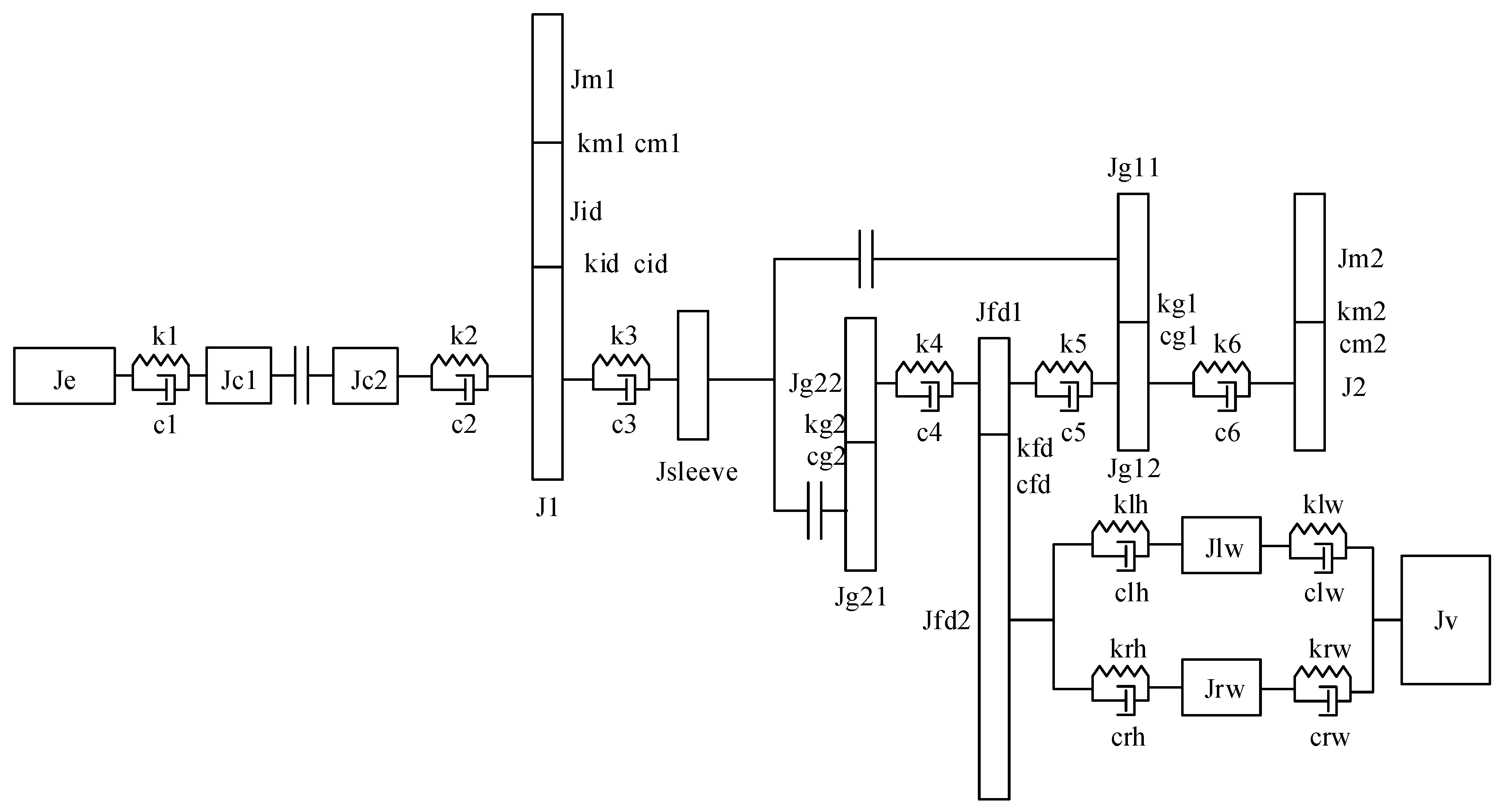
In order to study the torsional vibration characteristics of the HEV powertrain, simplify the engine and motor as masses and ignore the hydraulic model. When the clutch is engaged and the synchronizer operates in the first gear, the system has 16 degrees of freedom. In this case, the 16-DOF full-order model is shown in Figure 7, and the matrix form of the damped free torsional vibration dynamic equation [22] of the system is as follows:
J θ ¨ + C θ ˙ + K θ = 0
where the inertia matrix J , damping matrix C , stiffness matrix K , and angular displacement vector θ are as follows:
J = d i a g J e J c J m 1 J i d J 1 J m 2 J 2 J s g 1 J g 12 J f d 1 J g 22 J g 21 J f d 2 J l w J r w J v
where J c = J c 1 + J c 2 ,   J s g 1 = J s l e e v e + J g 11 .
The damping matrix is as follows:
C = C 1 C 2
where
C 1 = c 1 c 1 0 0 0 0 0 0 c 1 c 1 + c 2 0 0 c 2 0 0 0 0 0 c m 1 r m 1 2 c m 1 r m 1 r i d 0 0 0 0 0 0 c m 1 r m 1 r i d ( c m 1 + c i d ) r i d 2 c i d r i d r 1 0 0 0 0 c 2 0 c i d r 1 r i d c 2 + c i d r 1 2 + c 3 0 0 c 3 0 0 0 0 0 c m 2 r m 2 2 c m 2 r m 2 r 2 0 0 0 0 0 0 c m 2 r 2 r m 2 c m 2 r 2 2 + c 6 0 0 0 0 0 c 3 0 0 c 3 + c g 1 r g 11 2 0 0 0 0 0 0 c 6 c g 1 r g 12 r g 11 0 0 0 0 0 0 0 0 0 0 0 0 0 0 0 0 0 0 0 0 0 0 0 0 0 0 0 0 0 0 0 0 0 0 0 0 0 0 0 0 0 0 0 0 0 0 0 0 0 0 0 0 0 0 0 0
C 2 = 0 0 0 0 0 0 0 0 0 0 0 0 0 0 0 0 0 0 0 0 0 0 0 0 0 0 0 0 0 0 0 0 0 0 0 0 0 0 0 0 0 0 0 0 0 0 0 0 c 6 0 0 0 0 0 0 0 c g 1 r g 11 r g 12 0 0 0 0 0 0 0 c g 1 r g 12 2 + c 6 + c 5 c 5 0 0 0 0 0 0 c 5 c 5 + c 4 + c f d r f d 1 2 c 4 0 c f d r f d 1 r f d 2 0 0 0 0 c 4 c 4 + c g 2 r g 22 2 c g 2 r g 22 r g 21 0 0 0 0 0 0 c g 2 r g 21 r g 22 c g 2 r g 21 2 0 0 0 0 0 c f d r f d 2 r f d 1 0 0 c f d r f d 2 2 + c l h + c r h c l h c r h 0 0 0 0 0 c l h c l h + c l w 0 c l w 0 0 0 0 c r h 0 c r h + c r w c r w 0 0 0 0 0 c l w c r w c l w + c r w
Replace every c with k in the damping matrix to get the stiffness matrix K .
Parameters of the 16-DOF full-order model are listed in Table 1.
Let x = θ θ ˙ T , then Equation (6) can be rewritten in the form of Equation (9),
x ˙ = A x
where A = 0 I J 1 C J 1 K .
The damped natural frequency of the system was obtained by using the eig function in MATLAB to matrix A. Settings that are not mentioned use the default value. In addition, by ignoring the damping term and considering undamped free vibration, the undamped natural frequency can be obtained by applying the eig function to the inertia matrix and stiffness matrix. The natural frequencies of each order of the system are shown in Table 2.
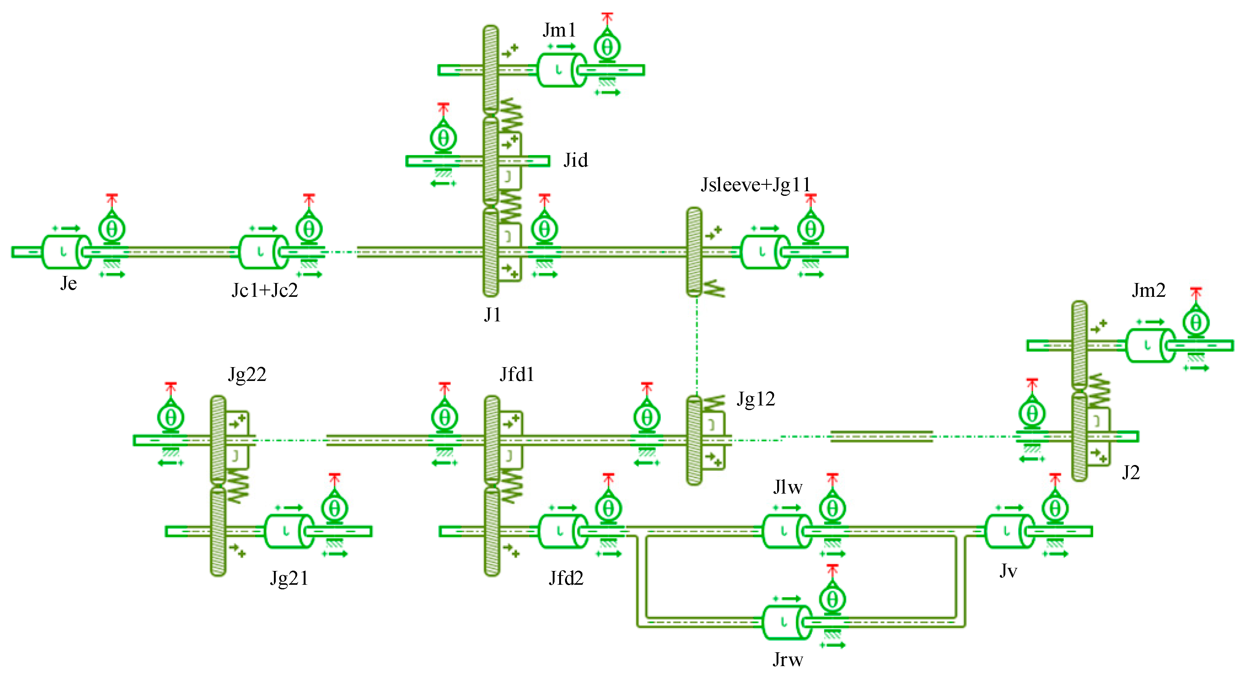
To facilitate dynamic simulation, this study constructs a torsional vibration dynamics model within the AMESim software environment, as shown in Figure 8. By employing the built-in linear analysis feature of AMESim, it is capable of calculating both the damped and undamped natural frequencies of the system. Let the print interval be 0.01 s, and use the standard integrator. The natural frequencies for each order are also listed in Table 2. The frequencies presented in Table 2 indicate that the computational results of MATLAB and AMESim are identical, laying a foundation for subsequent dynamic simulations using AMESim. It can be seen from Table 2 that the physical model built in AMESim and the mathematical model built in Simulink have the same natural frequency from the first stage to the 15th stage, both with and without damping, which means the mathematical model built in Simulink is accurate enough to describe the dynamic character of the HEV.
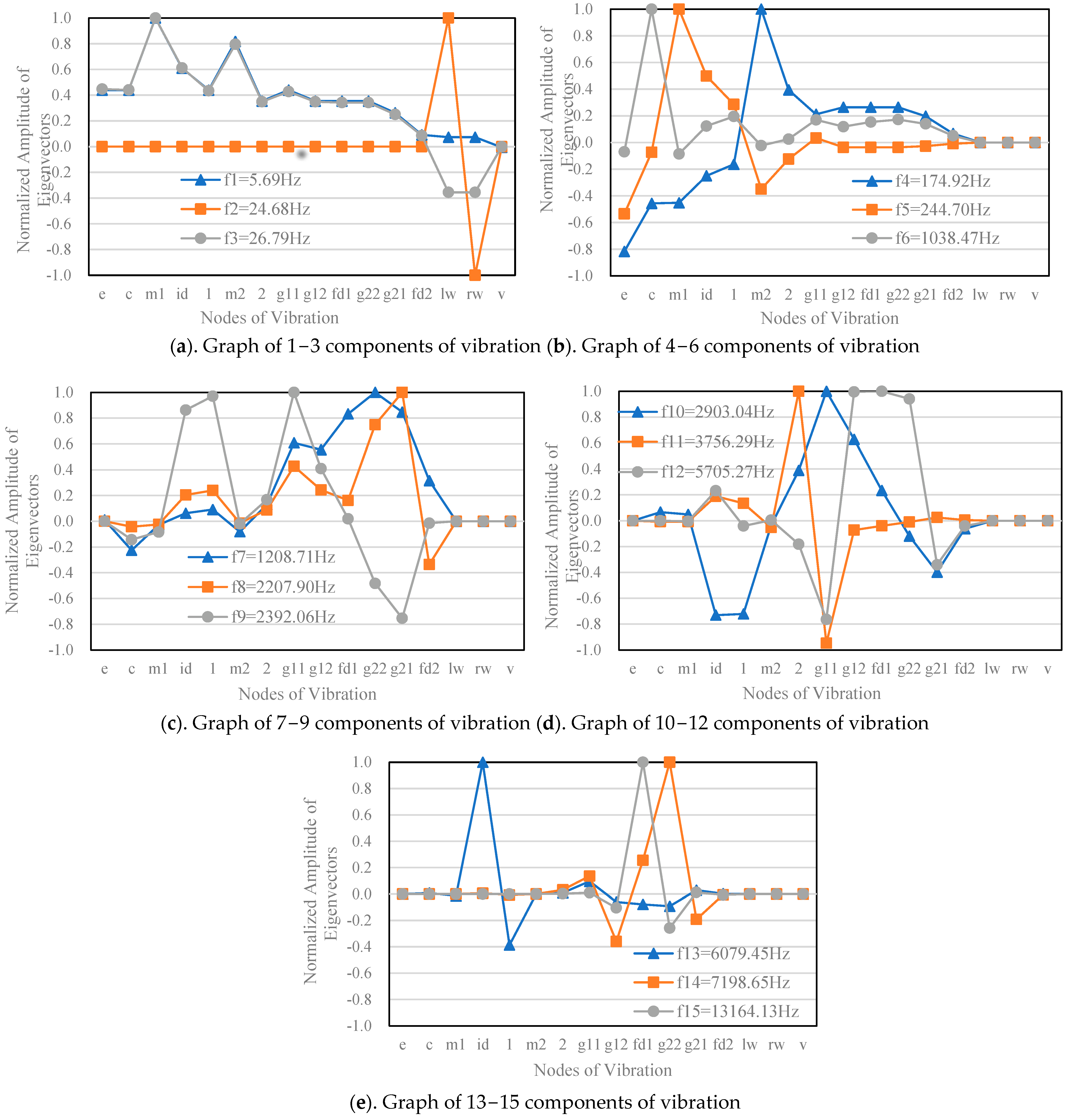
In addition, the linear analysis function can also be used to obtain the mode shapes of the system at various natural frequencies. Normalize the mode shapes and integrate them into the same coordinate system to obtain the relative amplitude between nodes, as shown in Figure 9.
At the first-order natural frequency, the relative amplitudes of nodes other than the vehicle body are relatively large. At the second-order natural frequency, the amplitude at the left and right wheels is maximum and the vibration phase is opposite. At the third frequency, the amplitudes at the two motors are relatively large, and the vibration phases of the left and right wheels are the same. At middle to high-order frequencies, vibrations are mainly concentrated in components outside the wheels and vehicle body.

4. The 4-DOF Dynamic Model of the HEV Powertrain

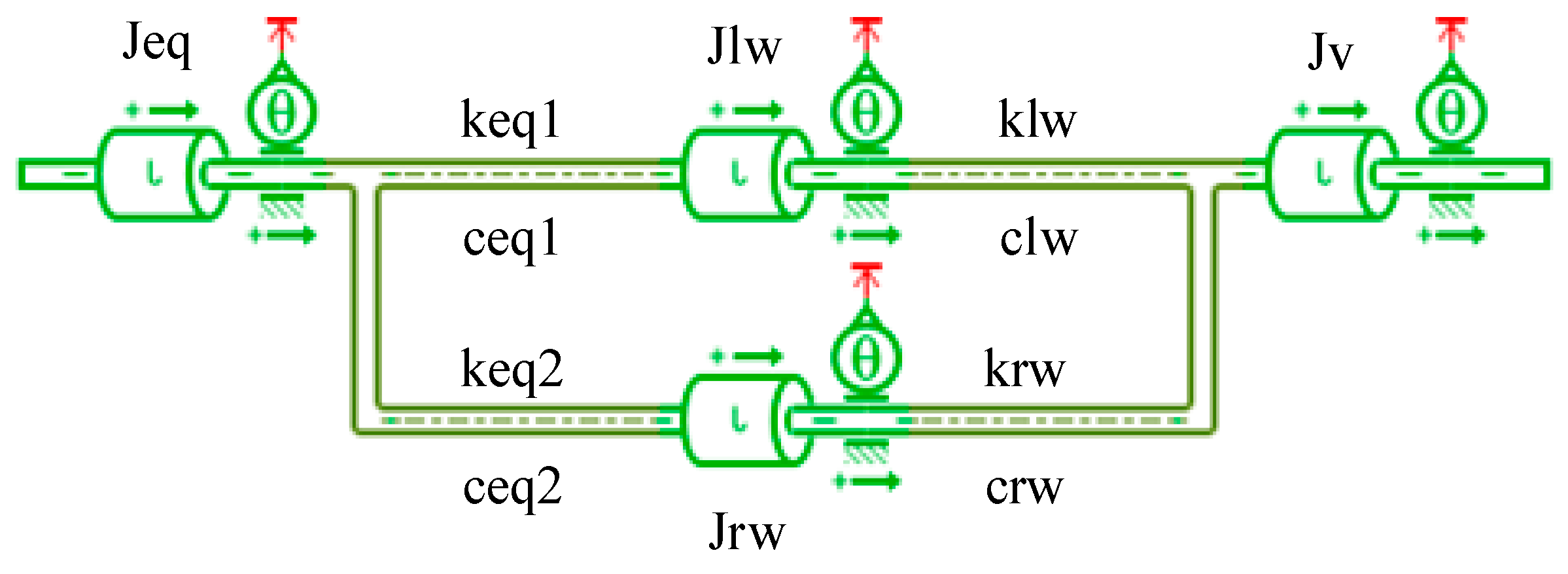
In order to facilitate the subsequent development of torsional vibration control algorithms, it is necessary to appropriately simplify the above 16-DOF model. The principle of simplification is to retain the low-frequency vibration characteristics of the system. Considering the large moments of inertia of the left and right wheel hubs and the entire vehicle in the system, these moments of inertia are retained, and other moments of inertia are equivalent to one moment of inertia using the method of kinetic energy equivalence. Similarly, the stiffness of the corresponding axis is also equivalently calculated. In order to simplify the calculation, mesh stiffness and mesh damping are ignored here. The calculation results of the simplified model indicate that such neglect is acceptable. Finally, the 16-degree-of-freedom model is considered as a 4-DOF model, as shown in Figure 10, where
J e q = [ ( J e + J c 1 + J c 2 + J 1 + J m 1 i i d 1 2 i i d 2 2 + J i d i i d 2 2 + J s l e e v e + J g 11 ) i g 1 2 + J g 12 + J 2 + J m 2 i m 2 2 + J f d 1 + J g 22 + J g 21 i g 2 2 ] i f d 2 + J f d 2
1 k e q 1 = ( 1 k 1 + 1 k 2 + 1 k 3 ) 1 i f d 2 i g 1 2 + ( 1 k 4 + 1 k 5 + 1 k 6 ) 1 i f d 2 + 1 k l h
1 c e q 1 = ( 1 c 1 + 1 c 2 + 1 c 3 ) 1 i f d 2 i g 1 2 + ( 1 c 4 + 1 c 5 + 1 c 6 ) 1 i f d 2 + 1 c l h
1 k e q 2 = ( 1 k 1 + 1 k 2 + 1 k 3 ) 1 i f d 2 i g 1 2 + ( 1 k 4 + 1 k 5 + 1 k 6 ) 1 i f d 2 + 1 k r h
1 c e q 2 = ( 1 c 1 + 1 c 2 + 1 c 3 ) 1 i f d 2 i g 1 2 + ( 1 c 4 + 1 c 5 + 1 c 6 ) 1 i f d 2 + 1 c r h
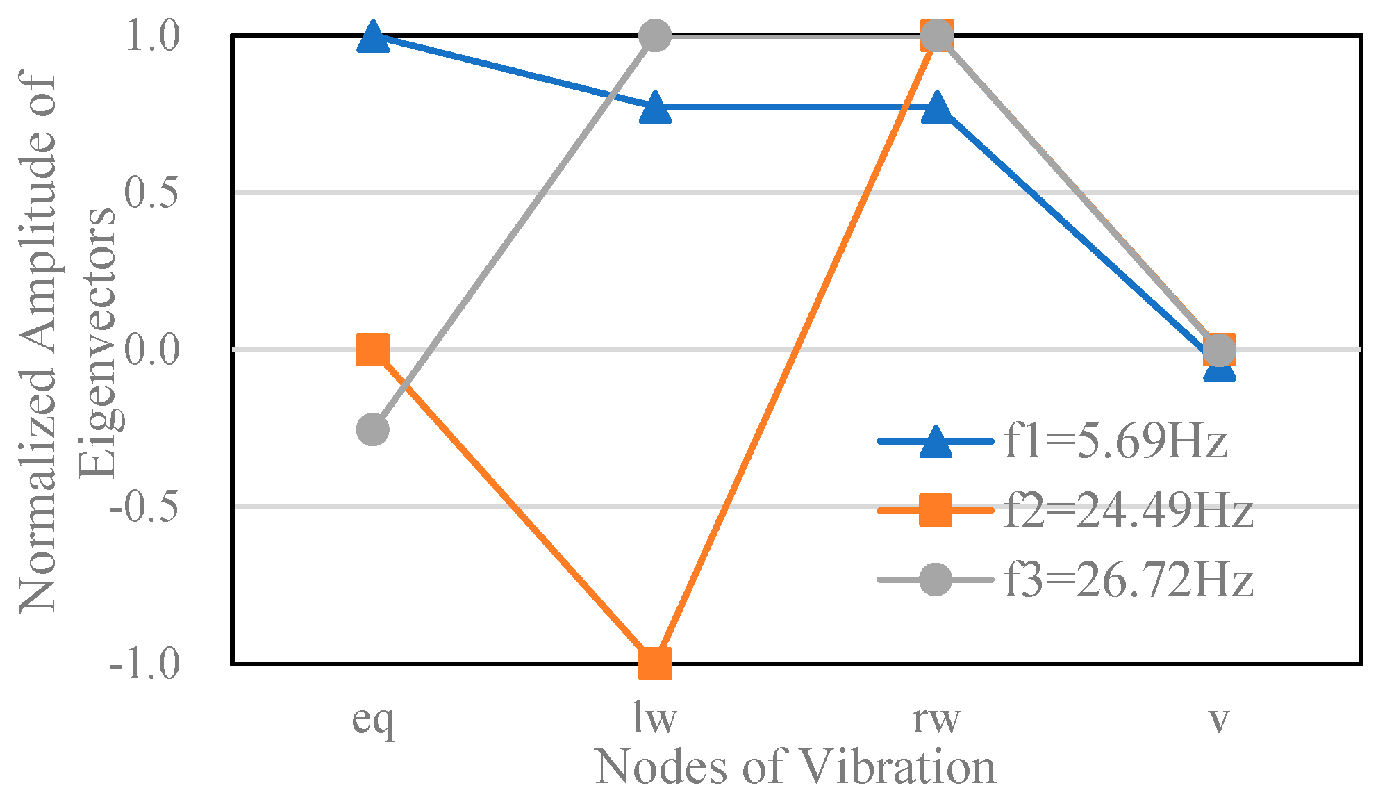
Table 3 shows the comparison of natural frequencies between the 16-degree-of-freedom model and the 4-degree-of-freedom model. Taking the damped natural frequencies as an example, the first natural frequency of the 16-DOF model is 5.70 Hz, corresponding to the torsional vibration of the equivalent inertia of the vehicle body. The second and third natural frequencies are 24.68 Hz and 26.78 Hz, respectively, corresponding to the torsional vibration of the left and right wheel hubs. The first three natural frequencies of the 4DOF model are 5.69 Hz, 24.49 Hz, and 26.71 Hz, respectively, which basically correspond to the first three natural frequencies of the 16-DOF model and retain the low-frequency vibration characteristics of the system. The mode shapes of the 4-DOF model are shown in Figure 11, and the relative amplitude characteristics of each component are basically consistent with the 16-DOF model, which once again verifies the accuracy of the 4-DOF model.
In order to further verify whether the time-domain response of the simplified model is consistent with the original model, the forced vibration analysis is conducted. In the fourth second, step torque inputs of 150 Nm and 200 Nm are applied to the engine and EM2, respectively. These inputs are idealized and are only used to obtain the time-domain response of the system. For the 4-DOF model, the step torque is applied to the equivalent moment of inertia J e q , and the magnitude of the step torque is obtained by multiplying the engine input and EM2 input by the corresponding torque amplification ratio and then adding them up. The response of forced vibration is shown in Figure 12. Analyzing Figure 12, the velocity of the 16-DOF model and the 4-DOF model at the 10th second are 18.3183 m/s and 18.3167 m/s, respectively. The overall velocity rising slope of the 4-DOF model is slightly lower than that of the 16-DOF model. Specifically, in the 10th second, the speed difference between the two is only 0.0087%. For the acceleration response, the two models have the largest difference of 0.316% at 5.08 s. Overall, it can be seen that under equivalent excitation, the vehicle speed and longitudinal acceleration response output of the two models are almost identical, further verifying the rationality of the simplified model.

5. Conclusions

In this work, two dynamic models are built. One is a complete longitudinal dynamic model for following studies instead of the real vehicle; the other is a simplified torsional vibration dynamic model to study the torsional vibration characteristics of the HEV. The main resonant frequency of the powertrain is calculated, and the results show that the 4-DOF simplified dynamic model has a similar response as the 16-DOF full-order dynamic model. As a result, the 4-DOF model can be used to develop effective control algorithms to suppress unwanted vibration during mode switching. In future research, the ODPDM will be used to guide the studies of the dynamic responses, such as the torsional vibration characteristics during frequent engine start/stop, motor tip-in/out, and mode switching. The 4-DOF simplified dynamic model will be used to develop effective control algorithms.

Author Contributions

Conceptualization, L.D.; methodology, L.D.; software, P.H.; validation, P.H.; formal analysis, G.B.; investigation, T.W.; resources, G.B.; data curation, H.L.; writing—original draft preparation, L.D.; writing—review and editing, T.W.; visualization, P.H.; supervision, T.W.; project administration, H.L.; funding acquisition, H.L. All authors have read and agreed to the published version of the manuscript.

Funding

This research received no external funding.

Data Availability Statement

The original contributions presented in the study are included in the article, further inquiries can be directed to the corresponding author.

Conflicts of Interest

Lihong Dai, Peng Hu are employees of Chery Jetour Automobile Co. Ltd. Guosheng Bian is employee of KUNTYE Vehicle System Co. Ltd. The paper reflects the views of the scientists, not the company.

References

  1. Castellano, A.; Stano, P.; Montanaro, U.; Cammalleri, M.; Sorniotti, A. Model predictive control for multimode power-split hybrid electric vehicles: Parametric internal model with integrated mode switch and variable meshing losses. Mech. Mach. Theory 2024, 192, 105543. [Google Scholar] [CrossRef]
  2. Beatrice, C.; Capasso, C.; Doulgeris, S.; Samaras, Z.; Veneri, O. Hybrid storage system management for hybrid electric vehicles under real operating conditions. Appl. Energy 2024, 354, 122170. [Google Scholar] [CrossRef]
  3. Squalli, J. Environmental hypocrisy? Electric and hybrid vehicle adoption and pro-environmental attitudes in the United States. Energy 2024, 293, 130670. [Google Scholar] [CrossRef]
  4. Andrenacci, N.; Giuli, G.; Genovese, A.; Pede, G. Flexible Charging to Energy Saving—Strategies Assessment with Big Data Analysis for PHEVs Private Cars. World Electr. Veh. J. 2024, 15, 197. [Google Scholar] [CrossRef]
  5. Jian, B.; Wang, H. Hardware-in-the-loop real-time validation of fuel cell electric vehicle power system based on multi-stack fuel cell construction. J. Clean. Prod. 2022, 331, 129807. [Google Scholar] [CrossRef]
  6. Shao, Y.; Zulkefli, M.A.M.; Sun, Z.; Huang, P. Evaluating connected and autonomous vehicles using a hardware-in-the-loop testbed and a living lab. Transp. Res. Part C Emerg. Technol. 2019, 102, 121–135. [Google Scholar] [CrossRef]
  7. Walker, P.; Zhu, B.; Zhang, N. Powertrain dynamics and control of a two speed dual clutch transmission for electric vehicles. Mech. Syst. Signal Process. 2017, 85, 1–15. [Google Scholar] [CrossRef]
  8. Walker, P.; Zhang, N. Active damping of transient vibration in dual clutch transmission equipped powertrains: A comparison of conventional and hybrid electric vehicles. Mech. Mach. Theory 2014, 77, 1–12. [Google Scholar] [CrossRef]
  9. Walker, P.; Zhang, N.; Tamba, R. Control of gear shifts in dual clutch transmission powertrains. Mech. Syst. Signal Process. 2011, 25, 1923–1936. [Google Scholar] [CrossRef]
  10. Shin, S.; Choi, S.B. Control-oriented modeling of wet clutch friction considering thermal dynamics. Mechatronics 2024, 99, 103146. [Google Scholar] [CrossRef]
  11. Wang, Y.; Wu, J.; Zhang, N.; Mo, W. Dynamics modeling and shift control of a novel spring-based synchronizer for electric vehicles. Mech. Mach. Theory 2022, 168, 104586. [Google Scholar] [CrossRef]
  12. Zhang, Z.; Yang, B.; Zhang, Y.; Li, L.; Zhao, B.; Zhang, T. Powertrain modeling and performance simulation of a novel flywheel hybrid electric vehicle. Energy Rep. 2023, 9, 4401–4412. [Google Scholar] [CrossRef]
  13. Ouyang, T.; Huang, G.; Li, S.; Chen, J.; Chen, N. Dynamic modelling and optimal design of a clutch actuator for heavy-duty automatic transmission considering flow force. Mech. Mach. Theory 2020, 145, 103716. [Google Scholar] [CrossRef]
  14. Mo, S.; Chen, K.; Zhang, Y.; Zhang, W. Vertical dynamics analysis and multi-objective optimization of electric vehicle considering the integrated powertrain system. Appl. Math. Model. 2024, 131, 33–48. [Google Scholar] [CrossRef]
  15. Park, G.; Lee, S.; Jin, S.; Kwak, S. Integrated modeling and analysis of dynamics for electric vehicle powertrains. Expert Syst. Appl. 2014, 41, 2595–2607. [Google Scholar] [CrossRef]
  16. Yakhshilikova, G.; Ruzimov, S.; Tonoli, A.; Mukhitdinov, A. Impact of Engine Inertia on P2 Mild HEV Fuel Consumption. World Electr. Veh. J. 2024, 15, 220. [Google Scholar] [CrossRef]
  17. Walker, P.; Zhang, N. Modelling of dual clutch transmission equipped powertrains for shift transient simulations. Mech. Mach. Theory 2013, 60, 47–59. [Google Scholar] [CrossRef]
  18. Zhang, J.; Tang, X.; Yu, H.; Zou, L. Multi-body dynamics and noise analysis for the torsional vibration of a power-split hybrid driveline. Proc. Inst. Mech. Eng. Part K J. Multi-Body Dyn. 2014, 228, 366–379. [Google Scholar] [CrossRef]
  19. Tang, X.; Yang, W.; Hu, X.; Zhang, D. A novel simplified model for torsional vibration analysis of a series-parallel hybrid electric vehicle. Mech. Syst. Signal Process. 2017, 85, 329–338. [Google Scholar] [CrossRef]
  20. Morandin, M.; Bolognani, S.; Faggion, A. Active torque damping for an ice-based domestic chp system with an spm machine drive. IEEE Trans. Ind. Appl. 2015, 51, 3137–3146. [Google Scholar] [CrossRef]
  21. Albers, A.; Albrecht, M.; Krüger, A.; Lux, F. New Methodology for Power Train Development in the Automotive Engineering-Integration of Simulation, Design and Testing. SAE Tech. Pap. 2001, 01, 3303. [Google Scholar]
  22. Kahraman, A. Free torsional vibration characteristics of compound planetary gear sets. Mech. Mach. Theory 2001, 36, 953–971. [Google Scholar] [CrossRef]
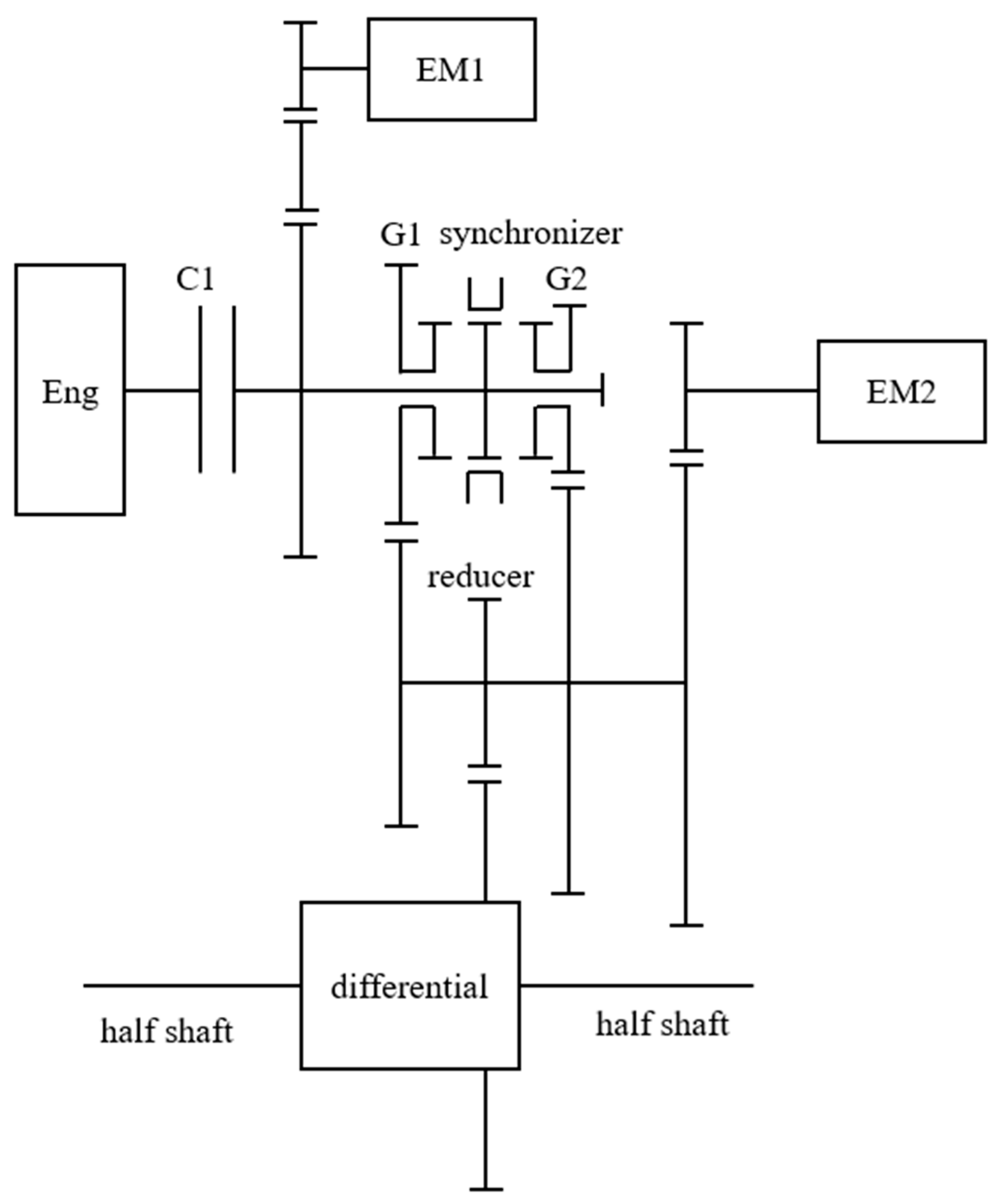
Figure 1. Schematic diagram of the HEV powertrain.
Wevj 15 00390 g001
Figure 2. Schematic diagram of the Cylinder.
Wevj 15 00390 g002
Figure 3. Engine model.
Wevj 15 00390 g003
Figure 4. Powertrain model.
Wevj 15 00390 g004
Figure 5. Motor model.
Wevj 15 00390 g005
Figure 6. Hydraulic model.
Wevj 15 00390 g006
Figure 7. Diagram of the 16-DOF full-order model.
Wevj 15 00390 g007
Figure 8. Torsional vibration dynamics model.
Wevj 15 00390 g008
Figure 9. Components of vibration. (a). Graph of 1–3 components of vibration. (b). Graph of 4–6 components of vibration. (c). Graph of 7–9 components of vibration. (d). Graph of 10–12 components of vibration. (e). Graph of 13–15 components of vibration.
Wevj 15 00390 g009
Figure 10. Diagram of the 4-DOF model.
Wevj 15 00390 g010
Figure 11. Components of vibration of 4−DOF model.
Wevj 15 00390 g011
Figure 12. Response of forced vibration. (a). Speed response. (b). Acceleration response.
Wevj 15 00390 g012
Table 1. Parameters of the 16-DOF model.
ParameterDescriptionParameterDescriptionParameterDescription
JeEnginek1stiffness of shaft 1c1damping of shaft 1
Jc1Clutch inner hubk2stiffness of shaft 2c2damping of shaft 2
Jc2Clutch outer hubk3stiffness of shaft 3c3damping of shaft 3
Jm1EM1 and drive geark4stiffness of shaft 4c4damping of shaft 4
JidIdle geark5stiffness of shaft 5c5damping of shaft 5
J1Driven gear of EM1k6stiffness of shaft 6c6damping of shaft 6
JsleeveSynchronizerkm1mesh stiffnesscm1mesh damping
Jg11Gear 11kidmesh stiffnesscidmesh damping
Jg12Gear 12kg1mesh stiffnesscg1mesh damping
Jg21Gear 21kg2mesh stiffnesscg2mesh damping
Jg22Gear 22kfdmesh stiffnesscfdmesh damping
Jfd1Drive gear of reducerkm2mesh stiffnesscm2mesh damping
Jfd2Driven gear of reducerklhstiffness of half shaftclhdamping of half shaft
Jm2EM2 and drive gearkrhstiffness of half shaftcrhdamping of half shaft
J2Driven gear of EM2klwstiffness of left wheelclwdamping of left wheel
JlwLeft wheelkrwstiffness of right wheelcrwdamping of right wheel
JrwRight wheel----
JvVehicle body----
Table 2. Natural frequencies.
FrequencyMATLAB (Hz)
Damped
AMESim (Hz)
Damped
MATLAB (Hz)
Undamped
AMESim (Hz)
Undamped
1st5.705.705.695.69
2nd24.6824.6824.6824.68
3rd26.7826.7826.7926.79
4th174.92174.92174.92174.92
5th244.70244.70244.70244.70
6th1038.881038.881038.471038.47
7th1208.741208.741208.711208.71
8th2208.002208.002207.902207.90
9th2391.872391.872392.062392.06
10th2905.392905.392903.042903.04
11th3753.863753.863756.293756.29
12th5707.455707.455705.275705.27
13th6077.216077.216079.456079.45
14th7194.697194.697198.657198.65
15th13,163.5313,163.5313,164.1313,164.13
Table 3. Comparison of natural frequencies.
Frequency16-DOF, Damped (Hz)4-DOF, Damped (Hz)16-DOF, Undamped (Hz)4-DOF, Undamped (Hz)
1st5.705.695.695.69
2nd24.6824.4924.6824.49
3rd26.7826.7126.7926.72
Disclaimer/Publisher’s Note: The statements, opinions and data contained in all publications are solely those of the individual author(s) and contributor(s) and not of MDPI and/or the editor(s). MDPI and/or the editor(s) disclaim responsibility for any injury to people or property resulting from any ideas, methods, instructions or products referred to in the content.