Article

Fuzzy Logic-Based Autonomous Lane Changing Strategy for Intelligent Internet of Vehicles: A Trajectory Planning Approach

1
School of Electronic and Information Engineering, Chongqing Three Gorges University, Chongqing 404130, China
2
College of Information and Engineering, Swan College, Central South University of Forestry and Technology, Hunan 410211, China
3
Chengdu Tangyuan Electric Co., Ltd., Sichuan 610046, China
4
China Information Technology Designing and Consulting Institute Co., Ltd., Beijing 100048, China
*
Author to whom correspondence should be addressed.
World Electr. Veh. J. 2024, 15(9), 403; https://doi.org/10.3390/wevj15090403
Submission received: 25 July 2024 / Revised: 19 August 2024 / Accepted: 28 August 2024 / Published: 3 September 2024

Abstract

:
The autonomous lane change maneuver is a critical component in the advancement of intelligent transportation systems (ITS). To enhance safety and efficiency in dynamic traffic environments, this study introduces a novel autonomous lane change strategy leveraging a quintic polynomial function. To optimize the trajectory, we formulate an objective function that balances the time required for lane changes with the peak acceleration experienced during the maneuver. The proposed method addresses key challenges such as driver discomfort and prolonged lane change durations by considering the entire lane change process rather than just the initiation point. Utilizing a fifth-order polynomial for trajectory planning, the strategy ensures smooth and continuous vehicle movement, reducing the risk of collisions. The effectiveness of the method is validated through comprehensive simulations and real-world vehicle tests, demonstrating significant improvements in lane change performance. Despite its advantages, the model requires further refinement to address limitations in mixed traffic conditions. This research provides a foundation for developing intelligent vehicle systems that prioritize safety and adaptability.

1. Introduction

Intelligent Vehicles (IVs) are an important part of the AI era and are of great significance to the development of both the automotive industry and society, playing a significant role in reducing traffic accidents and improving traffic efficiency. To realize autonomous driving in IVs, behavioral decision-making and trajectory planning are essential. These processes determine how the vehicle interprets and plans according to the surrounding environmental information and how it makes instantaneous driving instructions, thereby liberating the driver [1,2].
The realm of autonomous lane-changing in IVs encapsulates pivotal technologies such as intricate inter-vehicle environmental perception, decisive timing for lane changes, proficient trajectory planning, and robust control strategy formulation. A predominant focus has been observed on two primary facets of IV lane-change behavior worldwide, namely, lane change decision models and lane change trajectory planning methodologies. Widely researched rule-based and minimum safe distance decision models provide a foundation; for instance, the work by Feng et al. employed a gain function to scrutinize lane intention generation, relying on the minimum safe distance formula to evaluate the associated risk in lane-changing [3]. Similarly, Li et al. considered the practical scenario of symmetrical two-lane traffic flow and proposed an augmented distance constraint rule and a novel meta-automata traffic flow model, thereby enhancing the risk assessment involved in vehicle lane changes [4].
As an effective tool for dealing with uncertainty and fuzzy information, fuzzy logic greatly facilitates the implementation of automatic lane change technology in IVs [5]. However, IVs face many cybersecurity challenges in implementing automatic lane change capability, as it may become possible to tamper or interfere with key information such as sensing data and the control instructions of the vehicle through cyberattacks, potentially destroying the automatic lane change function of the vehicle and even causing serious traffic accidents [6]. Therefore, improving the network security performance of IVs while ensuring normal operation of the automatic lane change function has become an urgent problem that needs to be improved [7].
The primary objective of this study is to propose an efficient and safe autonomous lane change strategy for IVs based on Vehicle-to-Vehicle (V2V) communication technology. This research aims to address three key challenges: mitigating discomfort and reducing the duration of lane changes, considering the entire lane change process rather than just the initiation point, and integrating real-time V2V communication for improved decision-making and trajectory planning. In order to overcome these obstacles, this study provides the following work and contributions:
  • Fuzzy logic-based lane-changing decision model: We proposes a novel lane-changing decision model based on fuzzy logic and use a quintic polynomial function to plan the lane-changing trajectory. This approach optimizes both driving comfort and efficiency, effectively addressing the complexities involved in various lane-changing scenarios.
  • Trajectory optimization using Particle Swarm Optimization (PSO): An objective function is formulated that considers both the time required for lane-changing and the maximum acceleration, ensuring an optimal balance between these factors. The PSO algorithm is utilized for real-time trajectory optimization, leveraging Vehicle-to-Everything (V2X) communication capabilities for dynamic adjustments based on changing traffic conditions.
  • Agile lane-changing decision model for urgent scenarios: An agile decision model is developed to handle urgent lane-changing situations. The proposed decision model is capable of rapidly re-planning trajectories and communicating critical data back to the central information processing hub. Comprehensive simulations using Carsim and Simulink validate the capabilities of the model, demonstrating significant improvements in stability and safety during the lane-changing process.
The remainder of this article is organized as follows. Section 2 begins with an analysis of the autonomous lane change strategy predicated on V2X communication. Following this, Section 3 develops a free-lane-change decision model from the perspectives of fuzzy logic theory and safe lane change distance. Section 4 introduces an objective function constructed from the lane change time in the Vehicle-to-Everything environment. Based on the PSO algorithm, the lane trajectory is optimized and the optimal lane trajectory model is derived. Section 5 validates fuzzy logic-based lane change decision-making, and the trajectory planning is denoted using quintic polynomials. Finally, we validate the proposed algorithm through a joint simulation using Carsim and Simulink and present our conclusions.

2. Related Works

2.1. Autonomous Lane Change Strategy Based on V2X

Autonomous lane-changing behavior in IVs involves critical technologies, including complex inter-vehicle environmental perception, lane-changing timing determination, trajectory planning, and control strategy formulation. Researchers both domestically and internationally have predominantly concentrated on two aspects of IV lane-change behavior, namely, lane change decision models and trajectory planning methods. Both rule-based and minimum safe distance decision models have been widely studied. For instance, Ouyang et al. utilized a gain function to examine lane intention generation and relied on the minimum safe distance formula to assess lane-change risk [8]. In this approach, the vehicle executes a lane change action when the relevant conditions are satisfied; otherwise, it continues to maintain the vehicle following state. By integrating the actual circumstances of symmetrical two-lane traffic flow in the same direction, Zheng et al. enhanced the risk description of vehicle lane changes during driving and proposed an improved distance constraint rule and meta-automata traffic flow model [9].
In recent years, advancements in computer technology and artificial intelligence have allowed for the development of new behavioral decision methods for IVs. Wang et al. fused a Support Vector Machine (SVM) classifier with other technologies for lane-changing behavior decision-making in highway working conditions [10]. Tang et al. proposed a Recurrent Neural Network (RNN)-based intention inference model to address the time series prediction problem [11]. Accounting for the interaction between surrounding vehicles, this model inputs the sequential motion information of surrounding vehicles to calculate congestion in different lanes, then integrates it with the target vehicle state. Suh et al. analyzed factors affecting autonomous lane change in a mixed-traffic scenario with both autonomous and human-driven vehicles [12] and introduced an integrated model to identify human-driven vehicle lane-change intentions, integrating SVM and Random Forest (RF) to accurately identify lane-change behavior.

2.2. Trajectory Planning Methods

Scholars both domestically and internationally have conducted extensive research into the trajectory planning issue of IVs from multiple standpoints. Trajectory planning algorithms can be classified into artificial potential field algorithms [13], graph search algorithms [14], random sampling algorithms [15], curve fitting algorithms [16], and machine learning methods [17]. Diao et al. combined the advantages of the artificial potential field method and and other technologies, proposing a model prediction trajectory planning method [18]. This method’s objective function includes a potential function and vehicle dynamic parameters, allowing for trajectory planning based on vehicle dynamics. This approach combines artificial potential field planning with obstacle location and road structure while performing trajectory planning based on vehicle dynamics theory, enhancing the real-time response and accuracy of trajectory planning. Dong et al. employed an improved Rapidly-exploring Random Trees (RRT) model and cubic spline curve for safe and smooth motion planning of wheeled robots [19]. Hang et al. utilized a combination of reinforcement learning and network upgrading to form the Dueling Deep Q-Network (DQN) algorithm for autonomous vehicle secondary path planning [20]. Daoud et al. generated multiple trajectories corresponding to different accelerations, taking into account the position of the target vehicle and the effective range of longitudinal acceleration, then selected the most suitable trajectory based on the vehicle dynamics model [21]. Peng et al. devised a trajectory planning curve for IVs based on the fifth polynomial that enables them to return to their original lane during lane-changing [22]. This design can assist IVs in reacting to unpredictable and unexpected situations that may arise while the vehicle is moving towards its target lane. Polynomial curve trajectory planning can plan the entire trajectory simultaneously using the starting and final states of the vehicle, with local secondary planning of the trajectory to address unexpected situations during the trajectory planning process currently becoming a focus of research.

2.3. Network Security Protection Strategies

With the rapid development of ITS, the problem of network security cannot be ignored; therefore, this paper combines fuzzy logic with network security technology and proposes a network security protection strategy for automatic lane change of IVs based on fuzzy logic [23]. First, fuzzy logic is used to preprocess and parse the sensor data of the vehicle in order to extract the key information that is useful for making automatic lane-change decisions. By constructing an intrusion detection mechanism based on fuzzy logic, the network communication of the vehicle is monitored and analyzed in real time to identify potential cyberattack behaviors, ensuring normal operation of the automatic lane-change function and safe operation of the vehicle [24]. Through in-depth research and exploration, the proposed approach is expected to provide a safer, more efficient, and more reliable driving experience in the field of intelligent transportation.
The main innovations of this study lie in its holistic approach to lane-changing, which combines decision-making and trajectory planning with real-time V2V communication. We introduce a novel trajectory optimization function that balances comfort and efficiency, and we propose a method for real-time trajectory updates based on dynamic V2V data. This approach allows for more adaptive and responsive lane changing behavior in complex traffic scenarios.

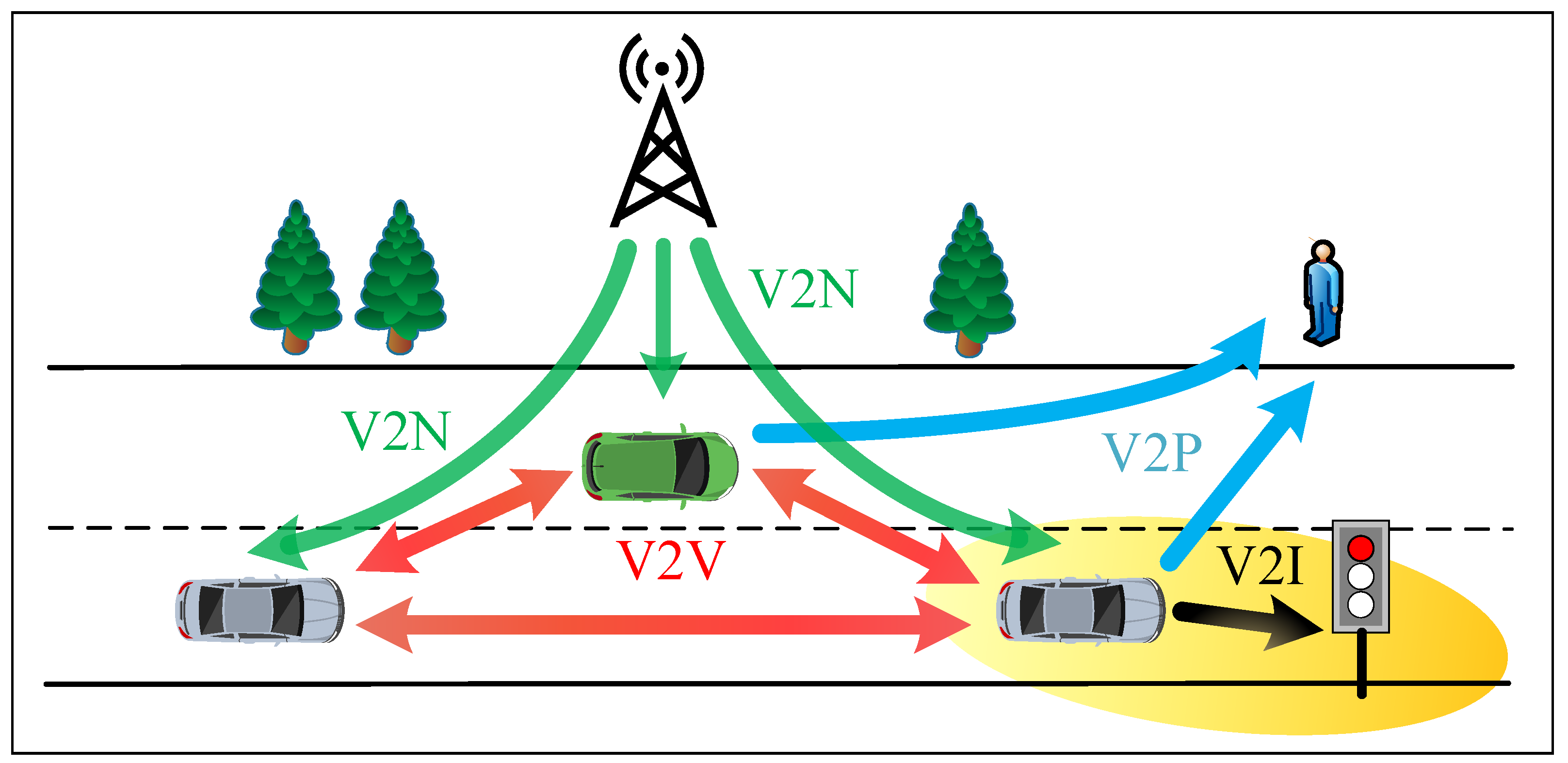
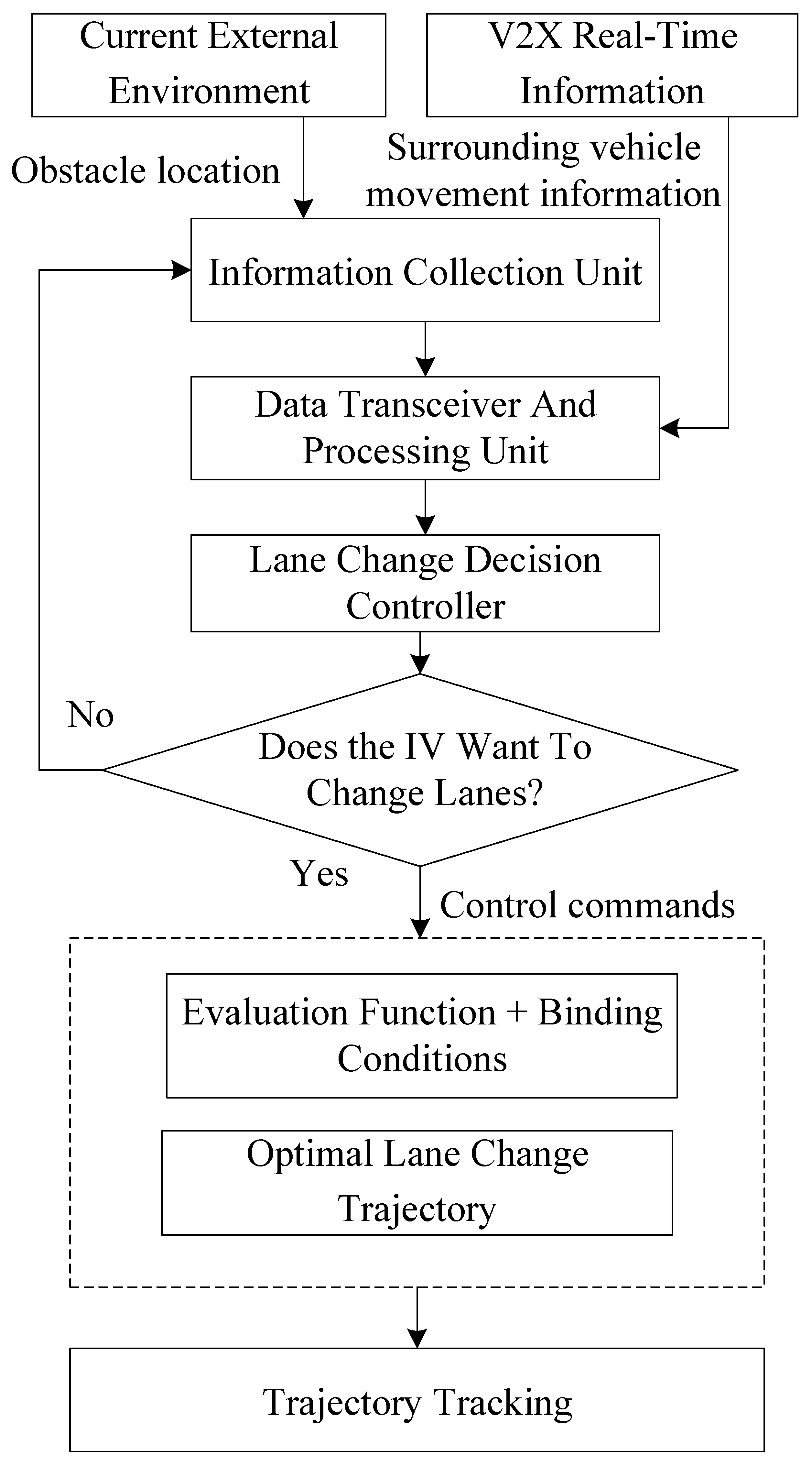
3. Network Architecture

Amid the rapid advancement of information technology, the Internet of Vehicles (IoV) has emerged as a key focal point and hotbed for research into the evolution of intelligent transportation systems [25]. Within the IoV environment, IVs are capable of obtaining their own vehicular motion data (such as position, speed, acceleration, etc.) through onboard sensors, and can also garner dynamic real-time information about their surroundings via wireless communication technologies. This capability allows them to grasp the motion states and change trends of nearby vehicles, anticipate other vehicles’ driving requirements, and accomplish autonomous and safe lane changes. In effect, intelligent vehicles contribute to a safe and efficient road traffic environment. This concept is illustrated in Figure 1.
Based on fuzzy logic, the lane-change decision of an IV determines its future driving behavior. Subsequently, it generates a safe, comfortable, and efficient driving trajectory that takes into account real-time information about obstacles, then follows this trajectory [26]. The motion state of vehicles in traffic can be unpredictable during lane changes. If sudden changes occur in the motion state of a traffic vehicle, the telematics transceiver unit assimilates real-time telematics information to re-plan the trajectory. In this paper, we incorporate real-time telematics information to facilitate real-time online decision-making and planning for IVs during the process of changing lanes. The specific structural framework of this approach is illustrated in Figure 2.
This research employs a combination of simulation tools and methodologies to develop and validate an autonomous lane change strategy for IVs using V2X communication. To achieve these objectives, we propose a comprehensive approach encompassing both decision-making and trajectory planning in a V2V environment. Our methodology involves developing a fuzzy logic-based lane-change decision model that incorporates V2V communication data, designing an optimized trajectory planning method using quintic polynomials and particle swarm optimization, implementing real-time trajectory updates based on V2V information, and validating the proposed strategy through simulations and real vehicle tests.

4. Fuzzy Logic-Based Lane Change Decision Model

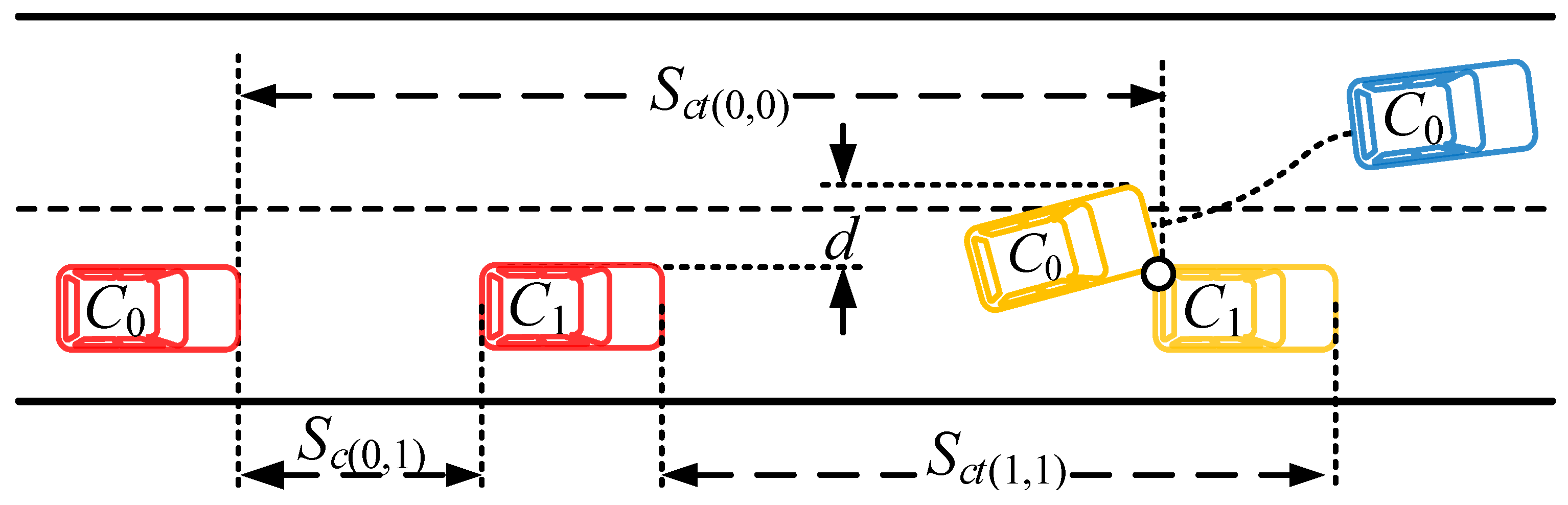
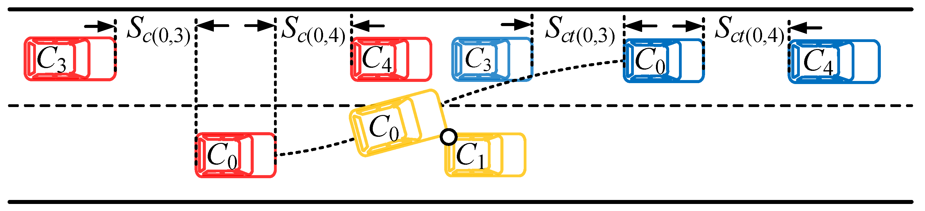
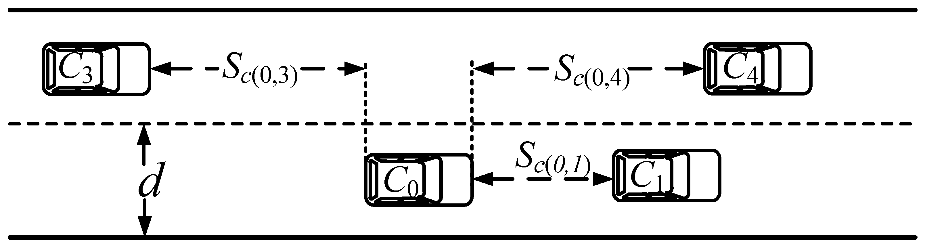
4.1. Lane Change Scenario Analysis

Lane change behavior can be classified into two types depending on varying driving objectives and influencing factors: forced lane changes and free lane changes [27]. In the free lane-change context, traffic vehicles are present in the IV’s current lane and in the adjacent lane, both ahead of and behind the vehicle. The distance between the IV and other vehicles on each lane is a key factor that affects lane change safety. During the lane change, it is crucial to ensure that the IV avoids collisions with the vehicles in its current lane while maintaining a safe distance from vehicles both in front of and behind it when maneuvering into the target lane. This requires careful timing when initiating a lane change, with safety distances being meticulously calculated in relation to the vehicles located both ahead of and behind the IV on its current and target lanes in order to ensure a safe lane change.
During normal lane-changing situations, the IV maintains a safe distance from the surrounding vehicles, without any need for emergency lane changes. It is assumed that both the current and target lanes provide ample space for a lane change. The schematic for the vehicle’s lane change is depicted in Figure 3, where ( x 0 , y 0 ) is the initial point when the vehicle is parallel to the lane marking, ( x i , y i ) is barely on the lane line, and ( x f , y f ) is the target position.
Due to the complex nature of lane changing scenarios, certain assumptions have been made for the purpose of simplifying the calculations and modeling in the lane-change scenario:
  • The speed of the vehicle remains constant during lane changes.
  • The lateral and longitudinal movements of the vehicle do not interfere with each other during lane changes.
  • The vehicles in the lane-change scenario use the same specifications and models.

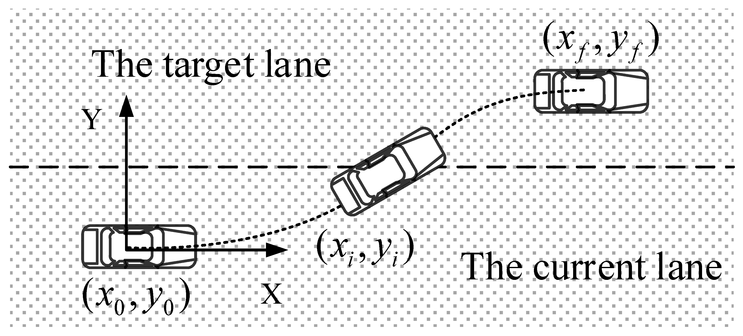
4.2. Polynomial-Based Trajectory Planning for Lane Changes

A fifth-order polynomial, or quintic polynomial, is employed in this study for trajectory planning due to its ability to provide a smooth and continuous path while satisfying necessary boundary conditions. Lower-order polynomials may not offer sufficient flexibility to control both the vehicle’s position and its derivatives, such as acceleration and jerk, at the start and end of the maneuver; conversely, higher-order polynomials, while offering more flexibility, can lead to increased computational complexity and potential instability.
Convergence Justification: The quintic polynomial is chosen because it inherently ensures convergence to the desired endpoint by satisfying all boundary conditions, including starting positions and final positions, velocities, and accelerations. This guarantees that the trajectory will smoothly transition from the start to the end of the lane change without divergence.
Controllability Justification: The fifth-order polynomial provides sufficient degrees of freedom to allow for precise control over the vehicle’s trajectory. This includes the ability to adjust the path in response to dynamic conditions while maintaining stability. The polynomial’s structure ensures that the trajectory remains smooth and continuous, which is essential to maintaining the safety and comfort of the vehicle during lane changes.
The path planning process using the quintic polynomial is shown in Equation (1):
x ( t ) = n = 0 5 a n t n y ( t ) = n = 0 5 b n t n .
In the above equation, a n and b n are the coefficients of the quintic polynomial to be determined. The state parameters of the vehicle at the beginning of the lane change, t 0 , are [ x ( t 0 ) , x ˙ ( t 0 ) , x ¨ ( t 0 ) , y ( t 0 ) , y ˙ ( t 0 ) , y ¨ ( t 0 ) ] , representing the longitudinal coordinates, velocity, and acceleration as well as the lateral coordinates, velocity, and acceleration, respectively. The state parameters at the end of the lane change, t f , are [ x ( t f ) , x ˙ ( t f ) , x ¨ ( t f ) , y ( t f ) ,   y ˙ ( t f ) , y ¨ ( t f ) ] . The state parameters of the vehicle at time t 0 can be acquired from onboard sensors, while these parameters at time t f can be solved by the road condition constraints and the optimization function.
As shown in Figure 3, at the beginning of the lane change the center of mass of the IV is at the coordinate origin and the direction of movement of the IV is parallel to the lane line. At this moment, Equation (1) can be defined as follows:
x t 0 = 0 ; x ˙ t 0 = v c ; x ¨ t 0 = 0 y t 0 = 0 ; y ˙ t 0 = 0 ; y ¨ t 0 = 0 .
Coupling Equation (1) with Equation (2) yields
a 0 = 0 ; a 1 = v c ; a 2 = 0 , b 0 = 0 ; b 1 = 0 ; b 2 = 0 .
At time t f , the IV completes the lane change. The vehicle is still driving parallel to the center line of the lane. Let the longitudinal displacement of the IV be x f ; the transverse displacement is generally the lane width y f and the longitudinal speed is v c . Under these conditions, substituting these conditions into Equation (1) yields
x ( t f ) = x f ; x ˙ ( t f ) = v c ; x ¨ ( t f ) = 0 y ( t f ) = y f ; y ˙ ( t f ) = 0 ; y ¨ ( t f ) = 0 .
Coupling Equation (1) with Equation (4), we derive
v c t f + a 3 t f 3 + a 4 t f 4 + a s t f 5 = x f 3 a 3 t f 3 + 4 a 4 t f 3 + 5 a 5 t f 4 = v c 6 a 3 t f + 12 a 4 t f 3 + 20 a 5 t f 3 = 0 b 3 t f 3 + b 4 t f 4 + b 5 t f 5 = y f 3 b 3 t f 2 + 4 b 4 t f 3 + 5 b 5 t f 4 = 0 6 b 3 t f + 12 b 4 t f 3 + 20 b 5 t f 3 = 0 .
In the above equation, t f stands for the time required to complete the lane change. By combining Equations (1), (3), and (5), the lane change trajectory function of the IV can be obtained as follows:
x ( t ) = v c t y ( t ) = y f ( 10 t f 3 · t 3 15 t f 4 · t 4 + 6 t f 5 · t 5 ) .
In Equation (6), y f represents the lateral displacement, which generally takes the lane width value. In the above system of equations, the only unknown is t f , which can be expressed by the individual coefficients of the polynomial. This indicates that as long as the value of t f is determined, the lane change trajectory can be determined. By differentiating y ( t ) with respect to the time, we can obtain the lateral velocity of the IV. Hence, in order for the IV not to collide with the vehicle in front in this lane, the following conditions must be met:
y ( t i ) = 0 t i v ( t ) d t > d
where y ( t i ) is the lateral displacement, t i is the critical collision moment, v ( t ) is the transverse velocity, and d represents the lane width.

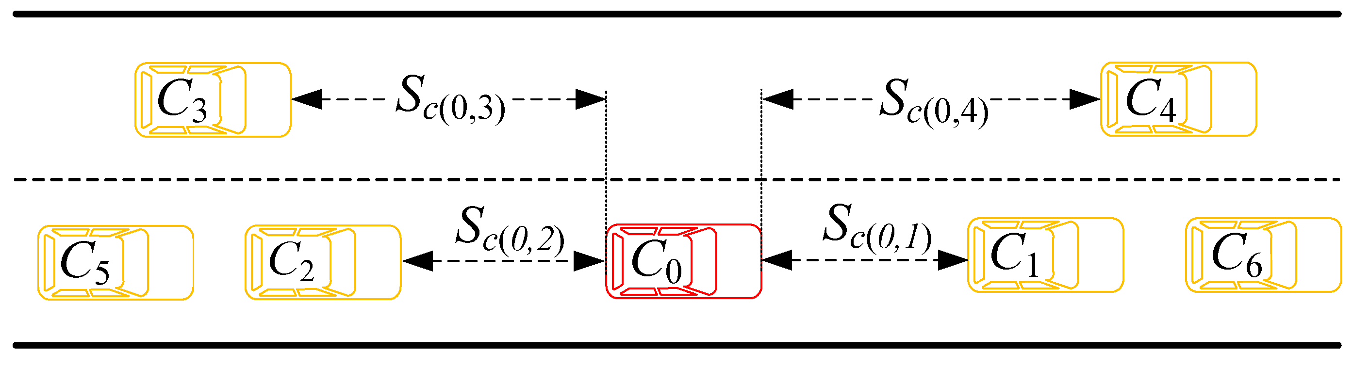
4.3. Lane Change Distance Model

As the IV maneuvers, the distance between the IV and other vehicles in the same lane must satisfy the longitudinal safety distance requirement. This paper utilizes a comprehensive safety distance model, represented by Equation (8):
D w = V r e l ( t n + t a + t s 2 ) + v 1 2 v 2 2 2 a 1 v 2 v r e l a 1 + D 0
where D w refers to the safe distance required for a lane change, v 1 and v 2 represent the respective speeds of the IV and the leading vehicle, v r e l is the relative speed difference between the two vehicles, t n stands for the driver’s reaction time, t a denotes the braking coordination time, t s signifies the braking deceleration growth time, D 0 indicates the braking distance, and a 1 is the road adhesion coefficient.
Figure 4 presents a typical lane change scenario, with C 0 (the IV) as the primary vehicle in its current lane, surrounded by other vehicles: C 1 and C 6 , the vehicles ahead in the current lane; C 2 and C 5 , the vehicles following in the current lane; C 3 , the vehicle following in the target lane; and C 4 , the vehicle ahead in the target lane. The distances between the IV and these vehicles are denoted as S c ( 0 , 1 ) , S c ( 0 , 4 ) , and S c ( 0 , 3 ) , respectively. When executing a lane change, the changing motion states of the surrounding traffic vehicles can critically impact the safety of the process. Therefore, it is crucial to ensure that the intelligent vehicle is safe and does not collide with other vehicles during lane changes.
This section focuses on studying the safety distance during the lane change. When establishing the lane change safety distance model, the vehicles ahead and behind in both the current and target lanes are discussed separately to establish the safety distance model between the IV and each of these traffic vehicles.
In establishing the safety distance for lane changes in the current lane, it is essential to consider the influence of the surrounding vehicles in the same lane on the safety of the IV’s ( C 0 ) lane change. There are two potential collision scenarios during the lane change; one involves the IV C 0 colliding with the vehicle ahead or behind in the current lane and the other entails a rear-end or oblique collision with the vehicle following in the current lane. Rear-end or oblique collisions mainly occur when the distance between the IV C 0 and the vehicle in the current lane is insufficient, while the safety between the vehicle following in the current lane and the IV C 0 is mainly determined with respect to the following vehicle. Therefore, this paper focuses on the safety distance between the IV C 0 and the vehicle C 1 ahead of it in the current lane.
Figure 5 illustrates the lane change process of IV C 0 when there is a vehicle C 1 ahead of it in the same lane. In the figure, S c ( 0 , 1 ) indicates the distance between C 0 and C 1 at the beginning of the lane change; the red, yellow, and blue colors indicate the initial state, the critical non-collision state, and the end of the lane change respectively, while the black dashed line depicts the planned lane-change trajectory.
It is assumed that after a certain moment t i , the IV C 0 (in the yellow state) narrowly avoids a collision with the vehicle C 1 ahead of it. The displacement of the IV C 0 during this period is denoted as y ( t i ) , where y ( t i ) > d , in which d represents the width of the vehicle ahead. Under this condition, the IV can evade a collision.
At the beginning of the lane change, if the distance S c ( 0 , 1 ) between the two vehicles is less than a certain value, a rear-end collision might occur between C 0 and C 1 ; here, S c t ( 0 , 0 ) and S c t ( 1 , 1 ) represent the respective transverse displacements of C 0 and C 1 after completing the lane change, while t i represents the critical moment of potential collision:
S c t ( 0 , 0 ) = v 0 t i ,
S c t ( 1 , 1 ) = v 1 t i ,
S c t ( 0 , 0 ) = S c ( 0 , 1 ) + S c t ( 1 , 1 ) .
Assuming that the driving states of the IV C 0 and the preceding vehicle C 1 remain unchanged over a short period and taking into account Equations (7) and (9)–(11), it is possible to find the critical collision moment S c ( 0 , 1 ) that determines the safe lane-change distance.
The lateral acceleration of the IV during motion is constrained by vehicle dynamics and road conditions. If the vehicle’s lateral acceleration exceeds its maximum limit, this can result in skidding or tipping over. The maximum lateral acceleration can be used to determine the critical collision moment t i , and consequently the safe distance for lane changes. Assuming that the maximum transverse acceleration of the IV C 0 during a lane change is a y m a x , the smallest critical collision moment t i would correspond to a y m a x ; from this, the minimum safety distance for lane changes can be derived.
y { min ( t i ) } = d = 0 min ( t i ) 0 min ( t i ) a y m a x ( t ) d t 2
min S c ( 0 , 1 ) = v 0 min t i v 1 min t i
In order to prevent a collision with the vehicle ahead of it in the current lane, the distance between vehicles should meet the established model for safe distance during lane changes.
S c ( 0 , 1 ) min S c ( 0 , 1 ) = v 0 min t i v 1 min t i
When creating a model for safe distance during lane changes into the target lane, it is necessary to predict the distance between the IV C 0 and other traffic vehicles upon completion of the lane change. This ensures that the distance between the IV C 0 and the vehicles ahead and behind in the target lane meets certain safety requirements after the lane change is complete. As shown in Figure 6, at the initial moment of the lane change, the target lane contains vehicles both ahead C 4 and behind C 3 the IV. The black dashed curve represents the planned lane change trajectory, while the blue vehicle C 0 denotes the position of the vehicle after the lane change is completed.
We first analyze the safe distance between the IV C 0 and the vehicle C 4 in front of it in the target lane. The transverse distance between the IV C 0 and the vehicle C 4 ahead of it in the target lane, denoted as S c ( 0 , 4 ) , can be measured at the beginning of the lane change using vehicular network communication. For this analysis, we assume that this value is already known. In the current operational conditions, the distance S c t ( 0 , 4 ) after completion of the lane change can be predicted:
S c t ( 0 , 4 ) = S c ( 0 , 4 ) + S c t ( 4 , 4 ) S c t ( 0 , 0 )
where S c t ( 4 , 4 ) represents the longitudinal displacement of traffic vehicle C 4 during the lane change and S c t ( 0 , 0 ) stands for the longitudinal displacement of the IV C 0 during the lane change. The speed of the IV C 0 remains the same during the lane change; thus, its longitudinal displacement can be expressed as
S c t ( 0 , 0 ) = v 0 t f ,
where v 0 is the speed of the IV C 0 and t f is the lane change time. The longitudinal displacement of traffic vehicle C 4 , which can be assumed to maintain a constant state during a short period, can be expressed as follows:
S c t ( 4 , 4 ) = v 4 t f + 1 2 a 4 t f 2 .
The speed of vehicle C 4 , denoted as v 4 , along with its longitudinal acceleration, denoted as a 4 , are integral to determining the vehicle’s displacement. By combining these variables, it is possible to calculate the predicted distance between the IV and vehicle C 4 after the lane change is completed:
D w f S c t ( 0 , 4 ) S c t ( 4 , 4 ) S c t ( 0 , 0 ) .
Similarly, the following vehicle in the target lane, vehicle C 3 , must maintain a safe distance from the IV C 0 upon completion of the lane change. To estimate this, it is possible to predict the distance between these two vehicles upon lane change completion under the current conditions:
S c t ( 0 , 3 ) = S c ( 0 , 3 ) + S c t ( 0 , 0 ) S c t ( 3 , 3 )
where S c t ( 0 , 3 ) is the distance between the IV C 0 and vehicle C 3 when the lane change is completed, S c ( 0 , 3 ) is the distance between the IV C 0 and vehicle C 3 at the initial moment of the lane change, and S c t ( 3 , 3 ) is the longitudinal distance traveled by vehicle C 3 during the lane change. Consequently, the safe distance between the IV C 0 and the rear vehicle in the target lane can be calculated as follows:
D w r S c t ( 0 , 3 ) S c t ( 0 , 0 ) + S c t ( 3 , 3 ) .
By integrating these models, the safe distance during the lane change can be expressed as
D w = V r e l ( t n + t a + t s 2 ) + v 1 2 v 2 2 2 a 1 v 2 v r e l a 1 + D 0 , S c ( 0 , 1 ) min S c ( 0 , 1 ) = v 0 min t i v 1 min t i , D w f S c t ( 0 , 4 ) S c t ( 4 , 4 ) S c t ( 0 , 0 ) , D w r S c t ( 0 , 3 ) S c t ( 0 , 0 ) + S c t ( 3 , 3 ) .

4.4. Polynomial-Based Trajectory Planning

As IVs navigate highway environments, their speeds will naturally fluctuate due to road conditions and interference from surrounding traffic [28]. Nonetheless, these vehicles will establish a target speed suitable for the current conditions when setting their driving tasks. It is worth noting that the IV will not initiate a lane change simply because its instantaneous speed does not match the target speed; it must also consider the speed variations of surrounding vehicles.
Taking into account the influence of preceding vehicles, this study introduces the concept of ’speed maintenance’. If there is a significant speed difference between the IV and the vehicle in front of it within the same lane, a lane change begins. We define and normalize the ’speed holding factor’ as follows:
δ v = 1 v c v g v c v 1 v g v c < v g
where v c represents the speed of the IV, v g is the planned speed of the IV, and v 1 is the speed of the vehicle in front of the IV.
When the IV is too close to the preceding car, relying solely on the speed maintenance factor is insufficient to effectively prompt the IV to change lanes. The distance between the IV and the car ahead also significantly impacts lane change decisions. While tailgating, the IV maintains a safe distance from the car in front to account for unexpected scenarios such as sudden decreases in speed. We propose that if the distance between the IV and the car ahead is less than the lane change safety distance model, then it will trigger a lane change. We define and normalize this ’distance holding factor’ as follows:
δ d = 1 S ω D ω S ω D ω S ω < D ω
where S w signifies the distance between the IV and the car in front and D w represents the desired distance of the IV.
The speed holding factor and the distance holding factor are two critical elements affecting an IV’s autonomous lane change. These factors are used as inputs for a fuzzy inference system and the car’s lane change intent serves as the output, facilitating the study of the lane change decision model.
Both the speed holding factor and distance holding factor are normalized and fuzzified into five levels. We set the speed difference factor δ v as a fuzzy subset with the categories ‘smaller’, ‘small’, ‘medium’, ‘large’, and ‘larger’ within the domain X, ranging from [ 0 , 1 ] . Similarly, the distance holding factor δ d is set as a fuzzy subset with the same categories within the domain Y, also ranging from [ 0 , 1 ] . The lane change willingness δ w is also fuzzified into five levels (‘weaker’, ‘weak’, ‘medium’, ‘strong’, ‘stronger’) within domain Z, with values between [ 0 , 1 ] . Membership functions for the speed holding factor δ v , distance holding factor δ d , and lane change willingness δ w are illustrated in Figure 7, Figure 8 and Figure 9, respectively [29].
For the input speed holding factor, distance holding factor, and output lane-change willingness, we establish reasonable fuzzy inference rules.

5. Trajectory Planning Using Quintic Polynomials

The objective function J of the lane change model must consider multiple factors, including driving efficiency, safety, and comfort, in order to adequately evaluate the trajectory’s overall performance. To simplify the operational complexity and enhance real-time trajectory planning, this study focuses on optimizing the vehicle’s driving efficiency, safety, and comfort. During lane changes, the primary safety concern is the vehicle deviating from the road boundary; to mitigate this, safety is ensured by introducing constraints on the vehicle’s lateral displacement in the planning algorithm. Two principal factors influencing lane changes are transverse acceleration and lane change time, which are inherently contradictory; therefore, this study uses the car’s maximum transverse acceleration and the lane change time as restrictions. To compensate for the magnitude difference between these two metrics, both are rendered dimensionless. This necessitates the introduction of the following function:
J a y m a x , t f = ε 1 a y m a x a y max * + ε 2 t f t f m a x .
The objective function J of the lane change model is governed by the balance between several evaluation indicators, where ε 1 and ε 2 represent the weight assigned to each. The condition ε 1 + ε 2 = 1 ensures that the total contribution of these indicators equals 1. Here, a y m a x symbolizes the maximum transverse acceleration during the lane change, whereas a y m a x * represents the maximum transverse acceleration the vehicle can reach, which is dictated by the car’s performance and road conditions. Moreover, t f m a x stands for the maximum time required for the IV to change lanes. By taking the second derivative of y ( t ) from the trajectory planning function, we obtain an expression for the maximum transverse acceleration a y :
a ( t ) = y f ( 60 t f 3 · t 180 t f 4 · t 2 + 120 t f 5 · t 3 ) .
After deriving the above equation, we can calculate a maximum value for it, represented as Equation (26):
a y max = y f 5.76 ε 1 5.76 y f 2 ε 2 4 .
Substituting this calculated maximum value of lateral acceleration into Equation (27) yields
J t f = ε 1 5.76 y f a y max * ε 1 5.76 y f 2 ε 2 4 + ε 2 t f t f max .
Through the trajectory evaluation function, we can ascertain the evaluation index size for each trajectory in the trajectory family. Solving for the minimum value of the evaluation function allows us to find the optimization function for the lane change trajectory:
min J t f s . t . t f min < t f < t f max .
For scenarios where the trajectory optimization function considers a y and t f as optimization variables, this paper introduces the particle swarm algorithm. The fitness function is defined as
min f t f .
A group of particles is initialized randomly as a feasible solution for the objective function. As they continue to iterate, their positions and velocities are updated. During this iterative process, the particles follow two optimal values: their own historical optimum, denoted as the individual position optimal solution p b e s t , and the current optimum for the entire group, which is the group position optimal solution g b e s t . The swarm searches for the optimal solution in the solution space in a step-by-step manner, guided by the following process:
  • Each individual in a group can be considered a particle; collectively, they form a particle swarm. Assuming a swarm of M particles exploring an N-dimensional space, each particle is assigned a ‘position’, as follows:
    X i = x i 1 , x i 2 , , x i N i = 1 , 2 , 3 M .
  • In each particle, the position serves as a potential solution. Its fitness value is calculated by inserting it into the objective function, with its worth determined based on this fitness value. The optimal position of each particle is recorded during each search process:
    P i = p i 1 , p i 2 , , p i N , i = 1 , 2 , 3 M .
  • The best position among all particles is regarded as the optimal solution of the entire particle population during this search process:
    G i = g i 1 , g i 2 , , g i N , i = 1 , 2 , 3 M .
  • This process repeats until the global optimal solution is found. Each search necessitates the update of particle velocity and position. The velocity of the i-th particle is represented as follows:
    V i = v i 1 , v i 2 , , v i N , i = 1 , 2 , 3 M .
  • The velocities and positions of the particles are updated using the following equations:
    v i d = w v i d + c 1 r 1 p i d x i d + c 2 r 2 p g d x i d , x i d = x i d + α v i d .
In the above equations, i = 1 , 2 , , M and d = 1 , 2 , , N are the local and global optimal positions, respectively. The acceleration constants c 1 and c 2 , known as the inertia factors, have values greater than or equal to 0, while r 1 and r 2 are random numbers distributed in the range [0,1] and α is a weighting factor that controls the speed. In terms of constraint settings, the constraints are attributed to the road conditions and the vehicle itself.
a y max a y max * v x < v x max v y < v y max t f min < t f < t f max

6. Results and Discussions

6.1. Parameter Setting

This study is primarily focused on the effect of the surrounding cars on the principal car’s lane change maneuvers. We consider both the vehicles ahead and behind in the target lane. Given that the rear car in the current lane trails behind the main vehicle and has a lower priority, we have established only a leading car in the current lane. The simulation environment is depicted in Figure 10.
The main vehicle C 0 is traveling at a constant speed of 20 m/s on the highway. By leveraging Vehicle-to-Vehicle (V2V) communication technology, it has identified that the speed of the leading car C 1 is too low to match the desired speed of C 0 . Therefore, the IV C 0 plans to initiate a lane change maneuver while maintaining a safe distance. The specific parameters for this scenario are illustrated in Table 1. The speed of vehicle C 1 is graphically represented in Figure 11.

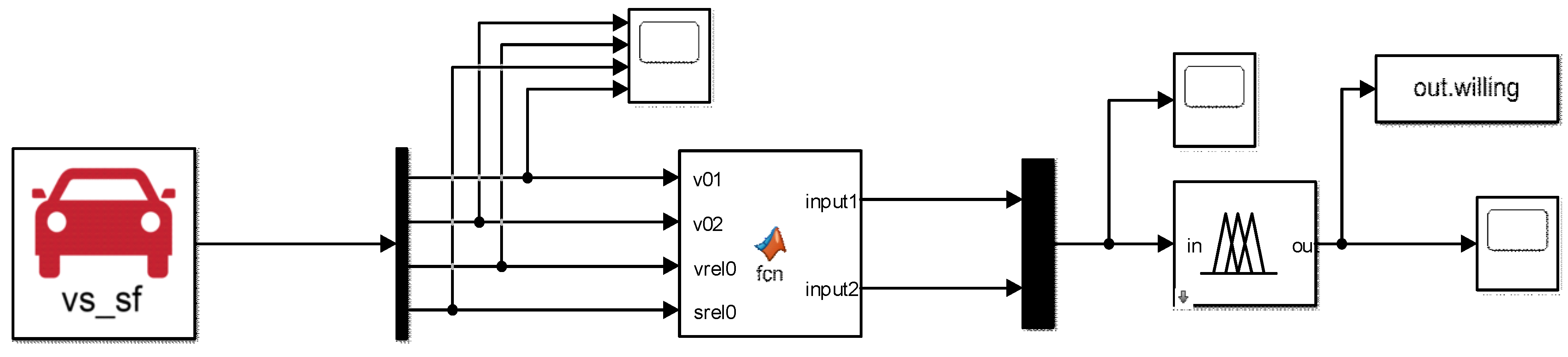
6.2. Free Lane-Change Decision Model
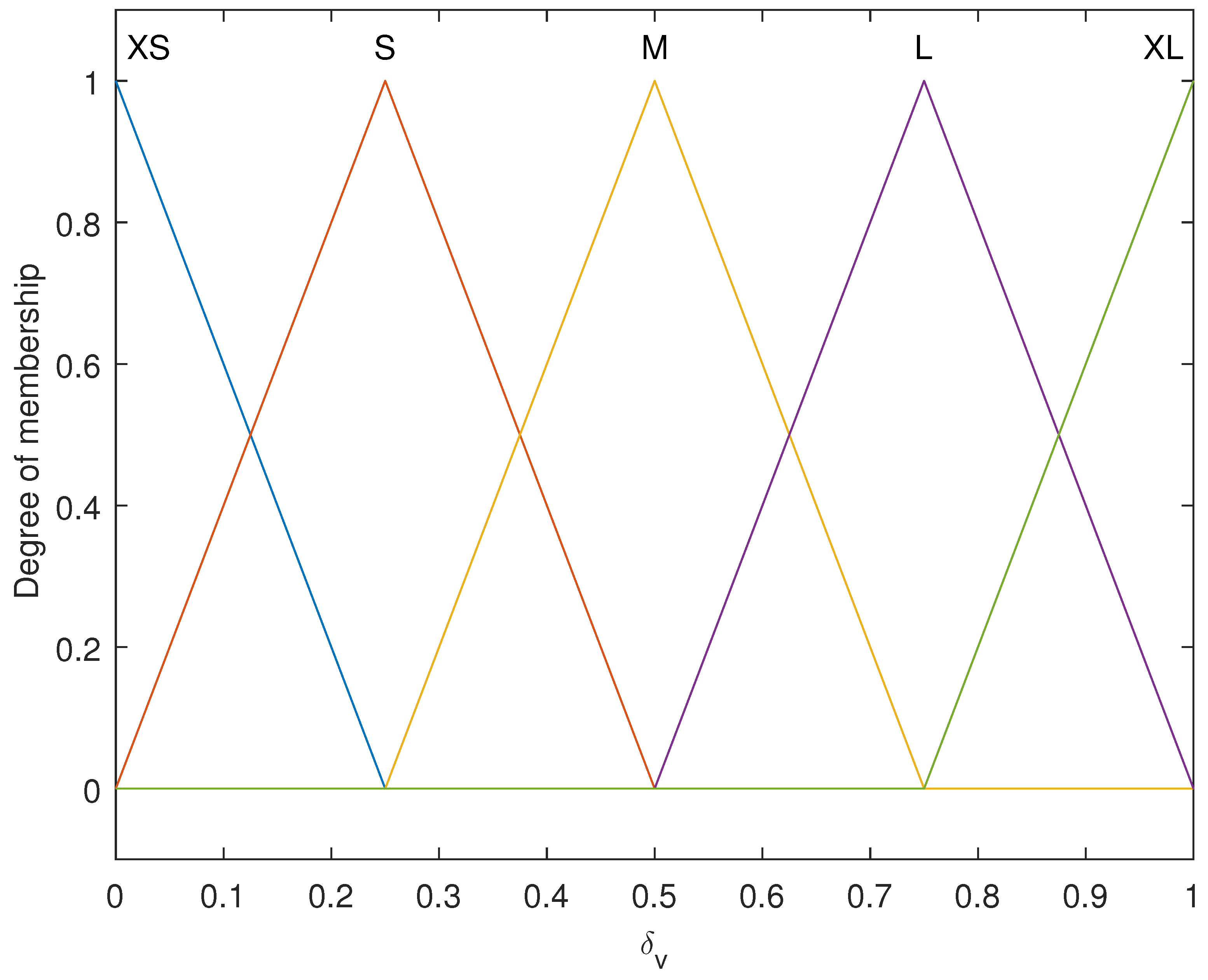
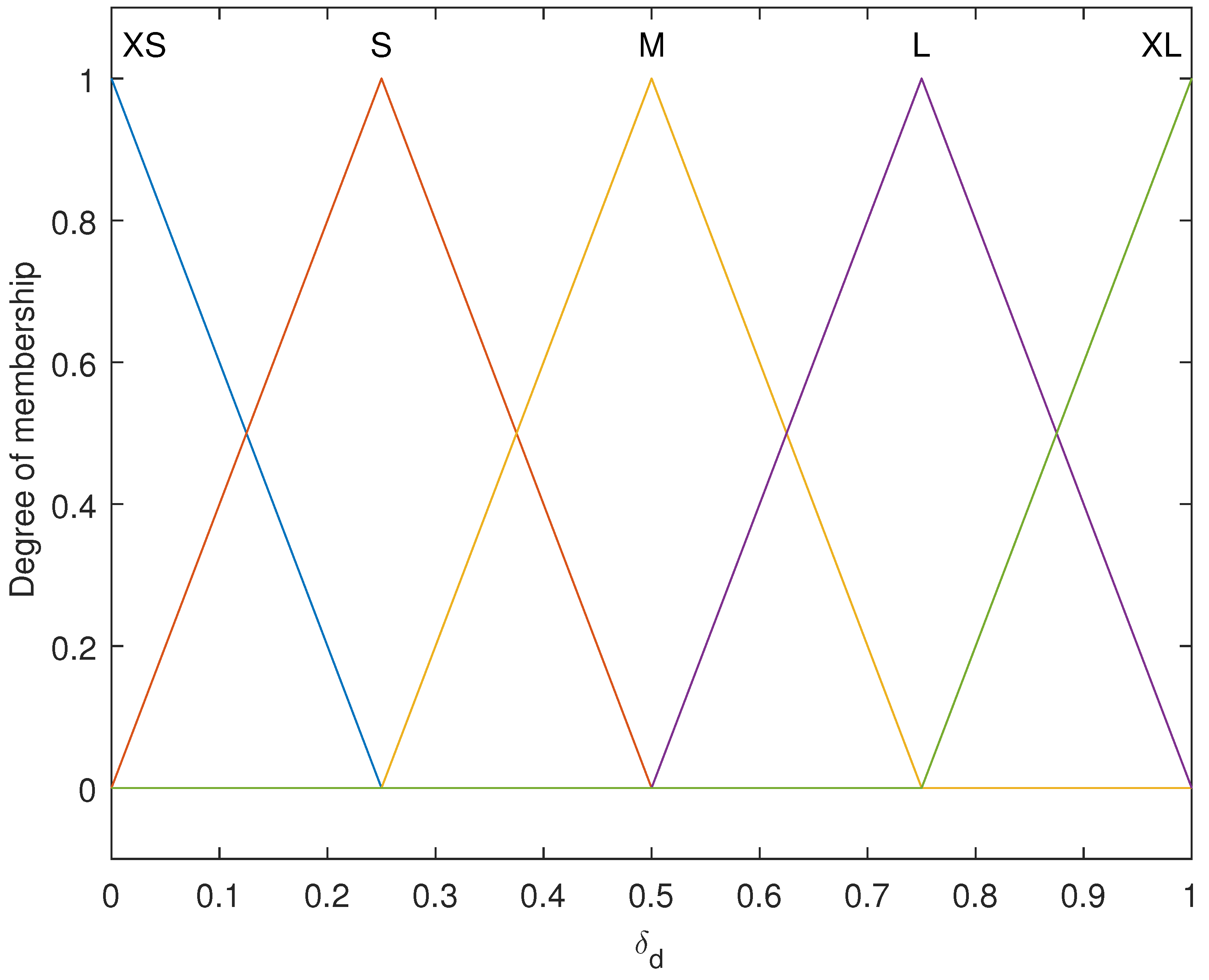
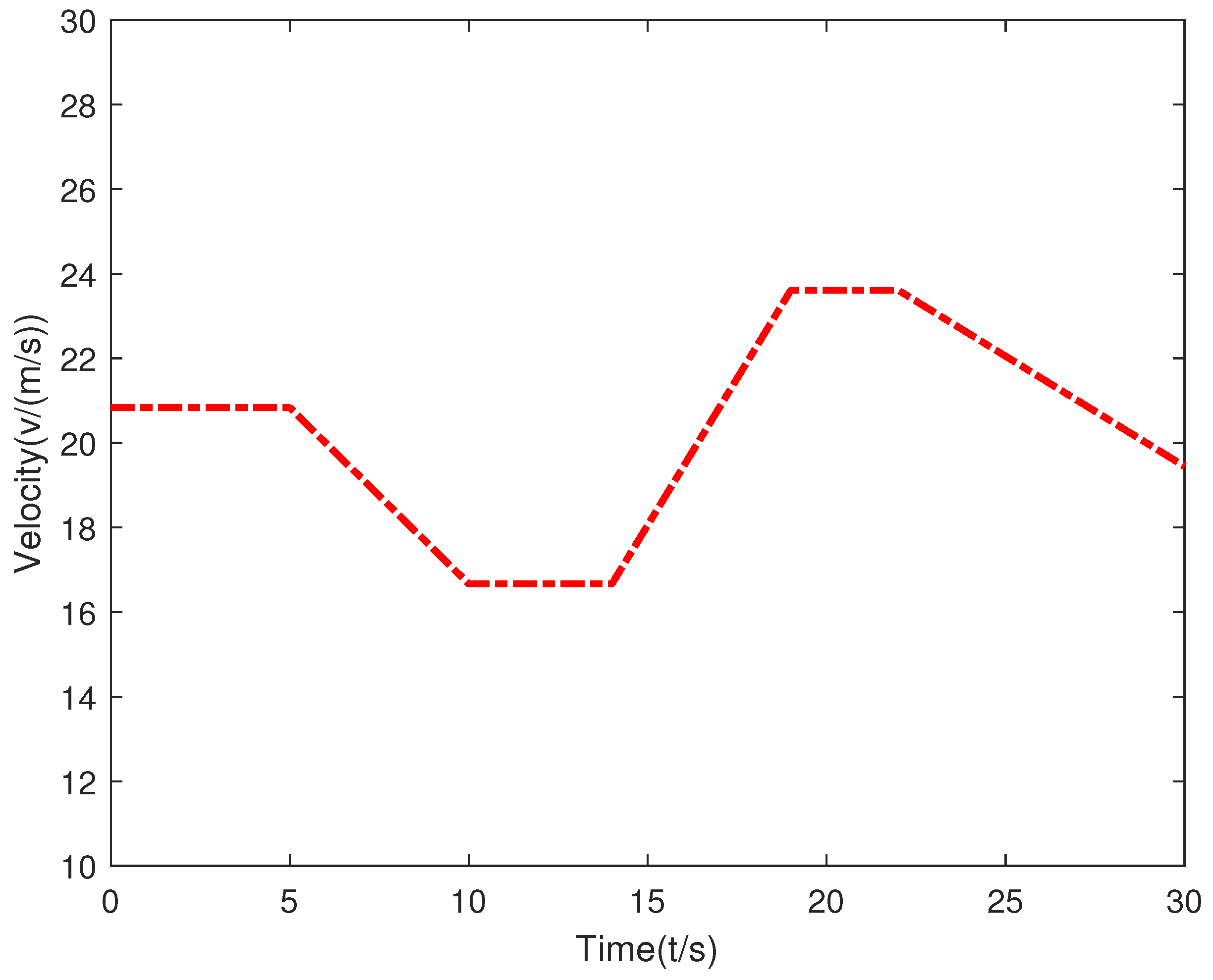
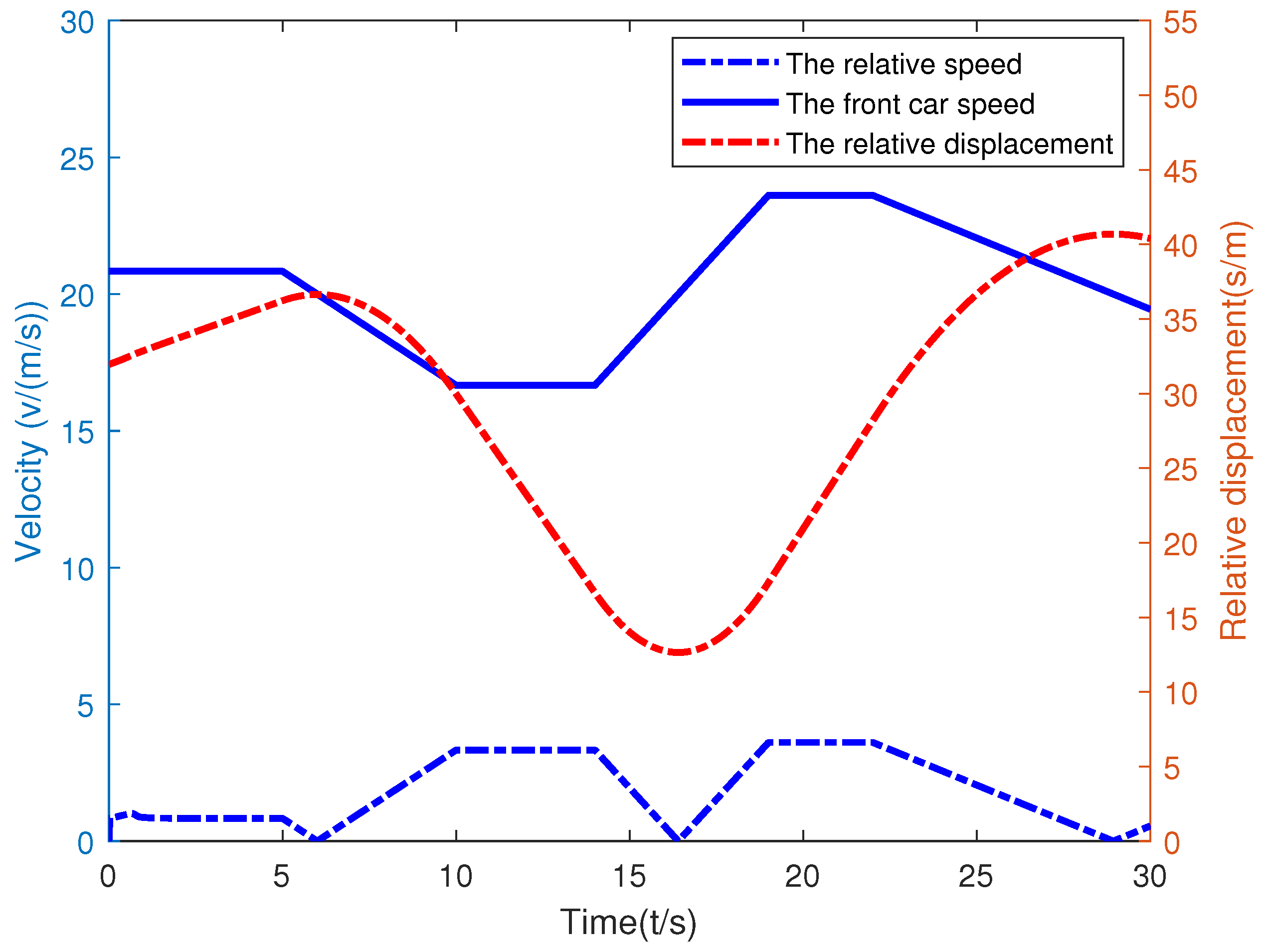
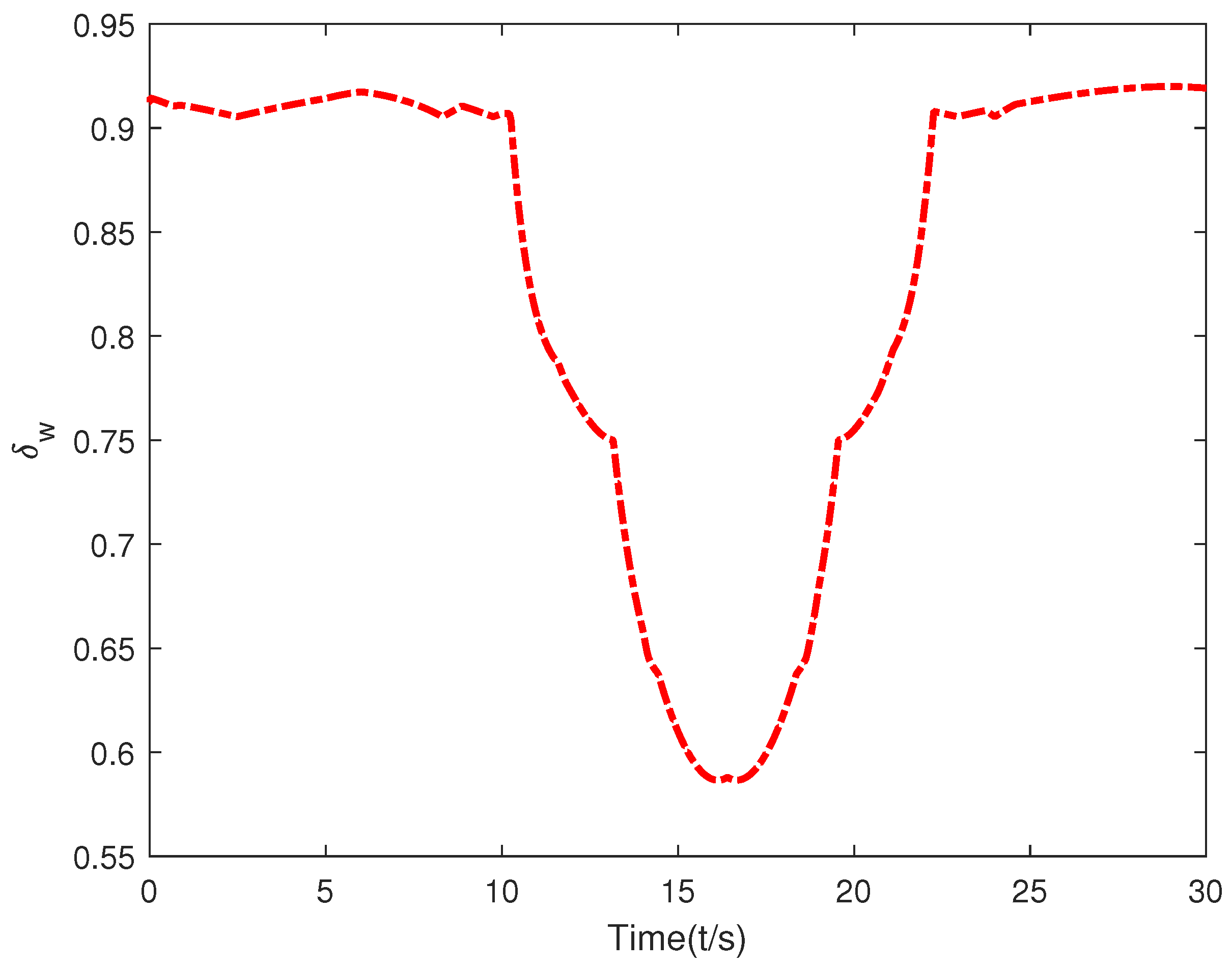
After vehicle C 0 has been driving for some time, the real-time data gathered via V2V communication is represented in Figure 12. In this figure, the solid blue line represents the speed of vehicle C 1 , the dotted blue line represents the real-time relative speed of vehicles C 0 and C 1 , and the red line represents the real-time relative distance of vehicles C 0 and C 1 . It can be observed that as the relative speed between C 0 and C 1 decreases, the relative distance between the two vehicles also progressively diminishes. Both factors follow the same trend, with the change in relative speed occurring before the change in relative distance.
A joint simulation platform was established using Simulink and CarSim, as depicted in Figure 13. CarSim exports relevant data to a lane change distance model coded in Matlab and subsequently outputs the current lane change intent via the lane change fuzzy controller, as shown in Figure 14.
  • For the time interval 0 t < 8 , the relative speed value is low and the relative distance value is high, maintaining the lane change inclination of the IV C 0 at a high level.
  • For the time interval 9 t < 16 , the relative speed increases and the relative distance decreases; consequently, the lane change inclination of the IV C 0 decreases.
  • For the time interval 17 t < 22 , as the relative speed and relative distance both increase, the lane change inclination of the IV C 0 decreases further.
  • For the time interval 23 t < 30 , with the relative speed low and the relative distance high, the inclination of the IV C 0 to change lanes remains at a high level.

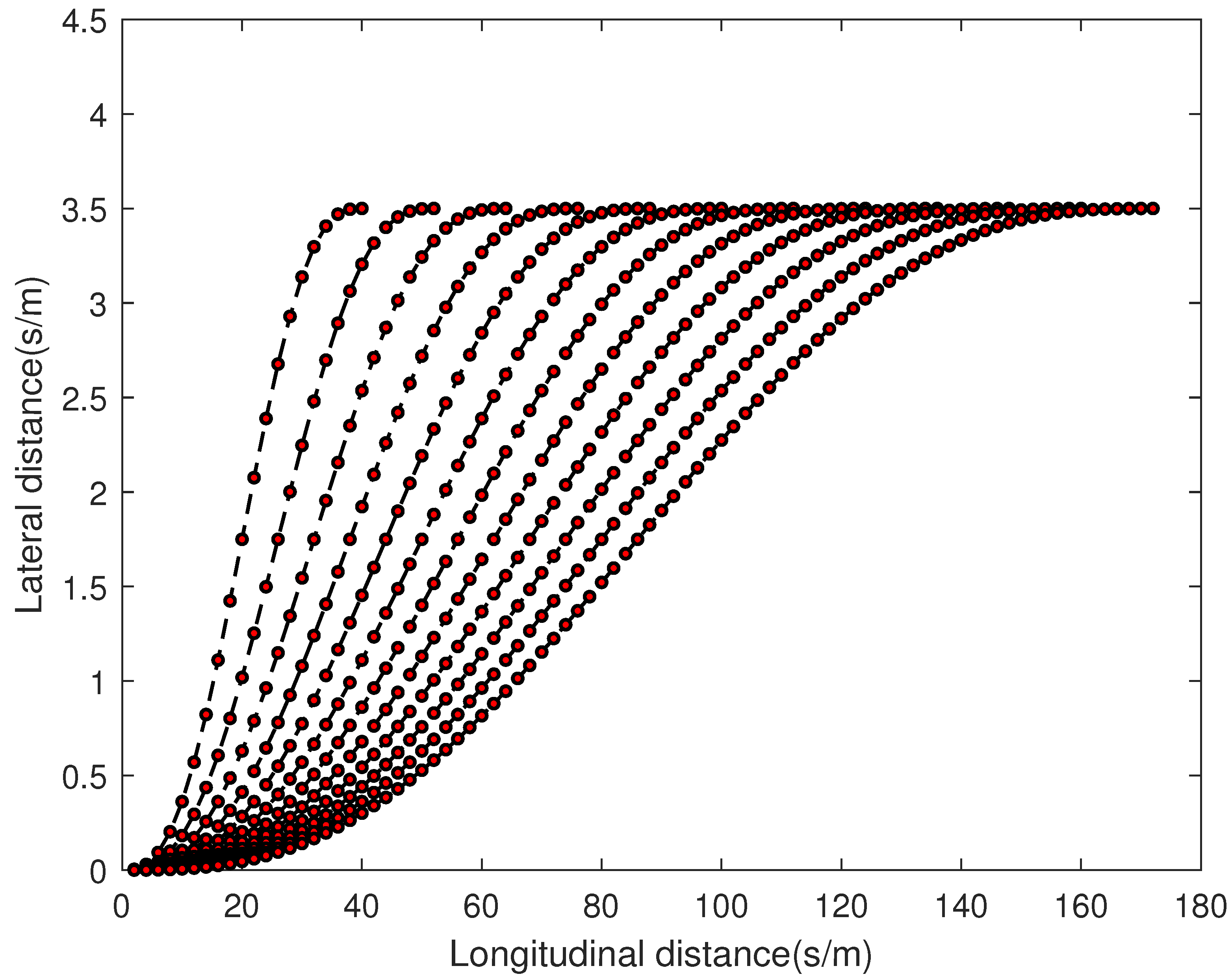
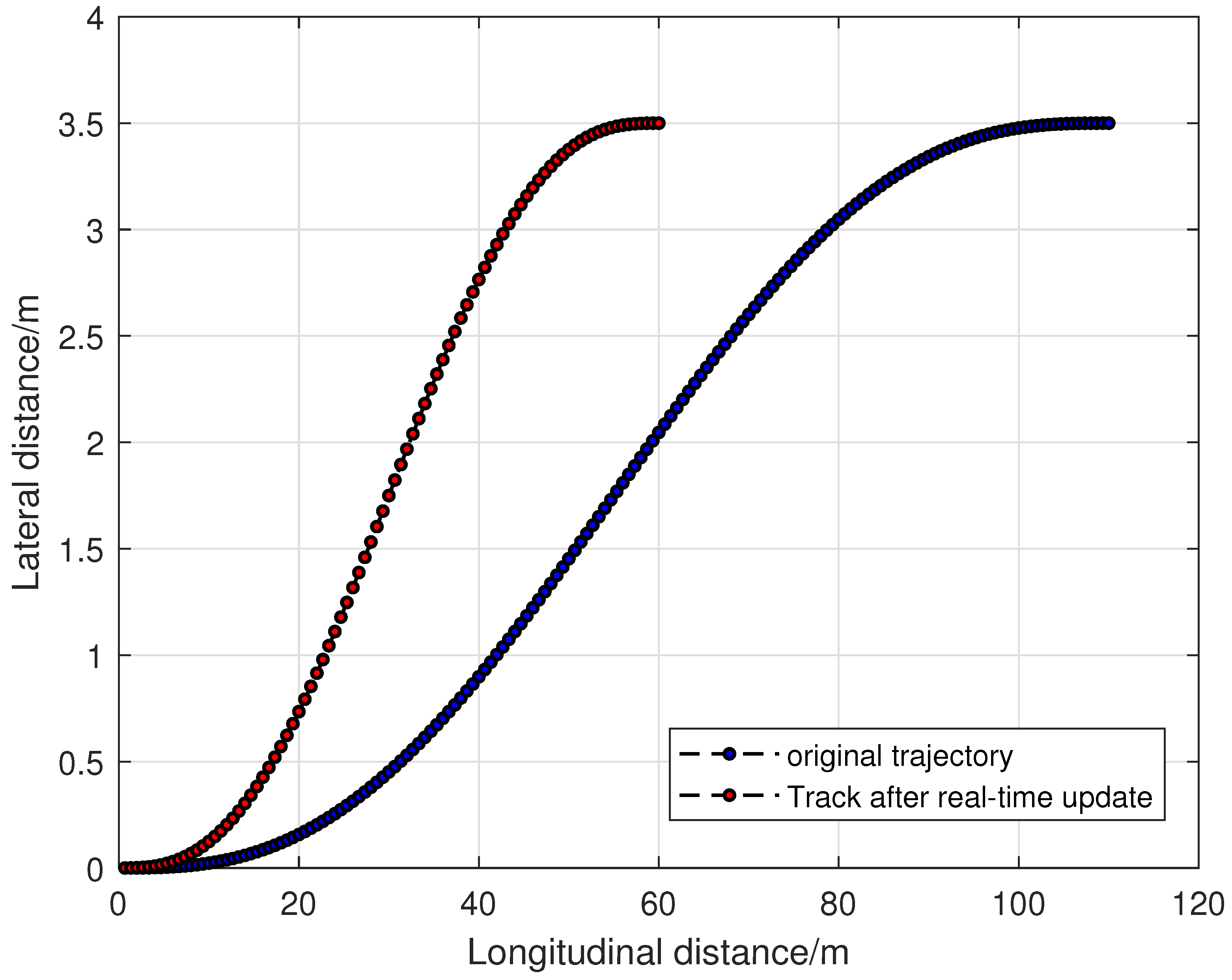
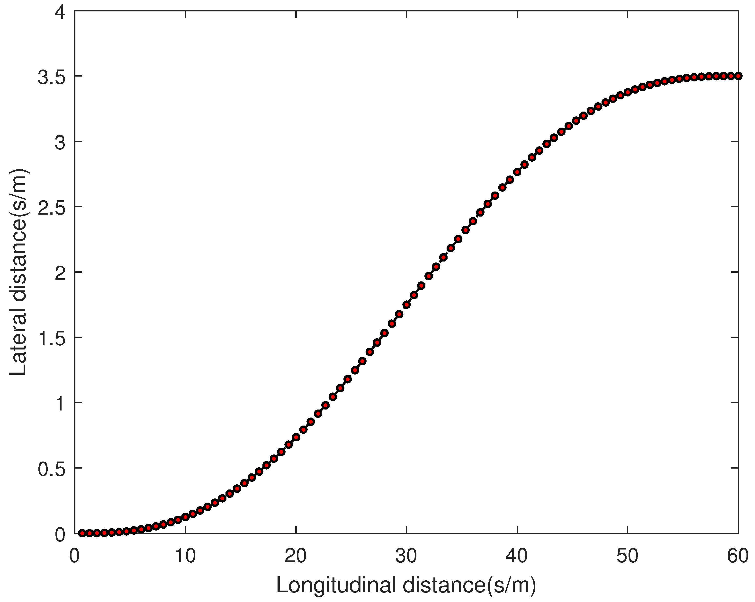
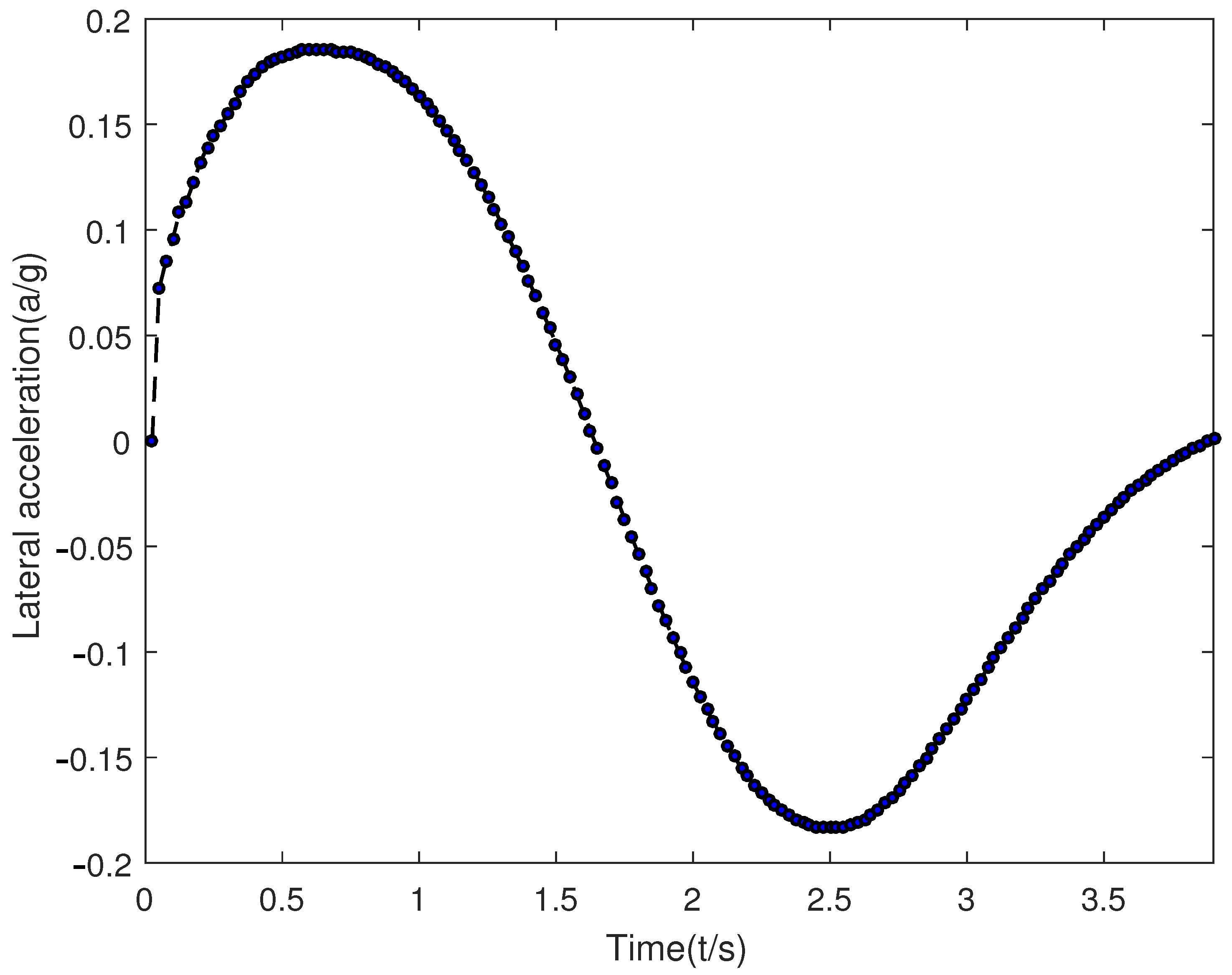
6.3. Autonomous Lane Change Trajectory Planning Verification

When the primary vehicle is driving under normal and free conditions, the resulting trajectory planning for different lane change times is depicted in Figure 15. The lane change time is constrained between 2 s and 10 s. As the lane change time increases, the longitudinal displacement required for the lane change also increases, ranging from 40 m to 170 m.
The PSO algorithm is used to solve the trajectory optimization function. Under various constraints, the optimal lane change time is 3.68 s. Compared with the lane change time of 4.90 s using the genetic algorithm, the efficiency of lane change can be effectively improved. The simulation results are shown in Figure 16.
The effect of the weight ratio on the lane change time is analyzed. The optimal values of different lane change trajectory optimization functions are calculated with varying weight ratios. The simulation results depicted in Figure 17 generally indicate that as the weight ratio ( ε 1 / ε 2 ) increases, the lane change time ( t f ) also displays an upward trend. Reader with an interest in other key performance indicators involved in autonomous lane change trajectory planning, such as vehicle location, acceleration, and lateral distance, can refer to our previous results in [30].
The maximum lateral acceleration of the vehicle under different lane change trajectories was calculated using Matlab for different weight ratios. It can be observed that the influence of the weight ratio ( ε 1 / ε 2 ) on the maximum transverse acceleration of the vehicle is inverse to its impact on the lane change time. Generally, as the weight ratio increases, the value of the vehicle’s lateral acceleration decreases. In situations requiring an emergency lane change, a smaller value is assigned to ε 1 / ε 2 , whereas when a higher comfort level is desired a larger value is assigned to ε 1 / ε 2 .
The IV is able to receive real-time information via V2V; in the event of an emergency, a second trajectory can be planned, as shown in Figure 18. Assuming emergency braking of the vehicle in front, in the case of an IV lane change, the red dotted line represents the updated trajectory, at which point the longitudinal displacement changes from 110 m to 60 m, remaining within the safe lane change distance.

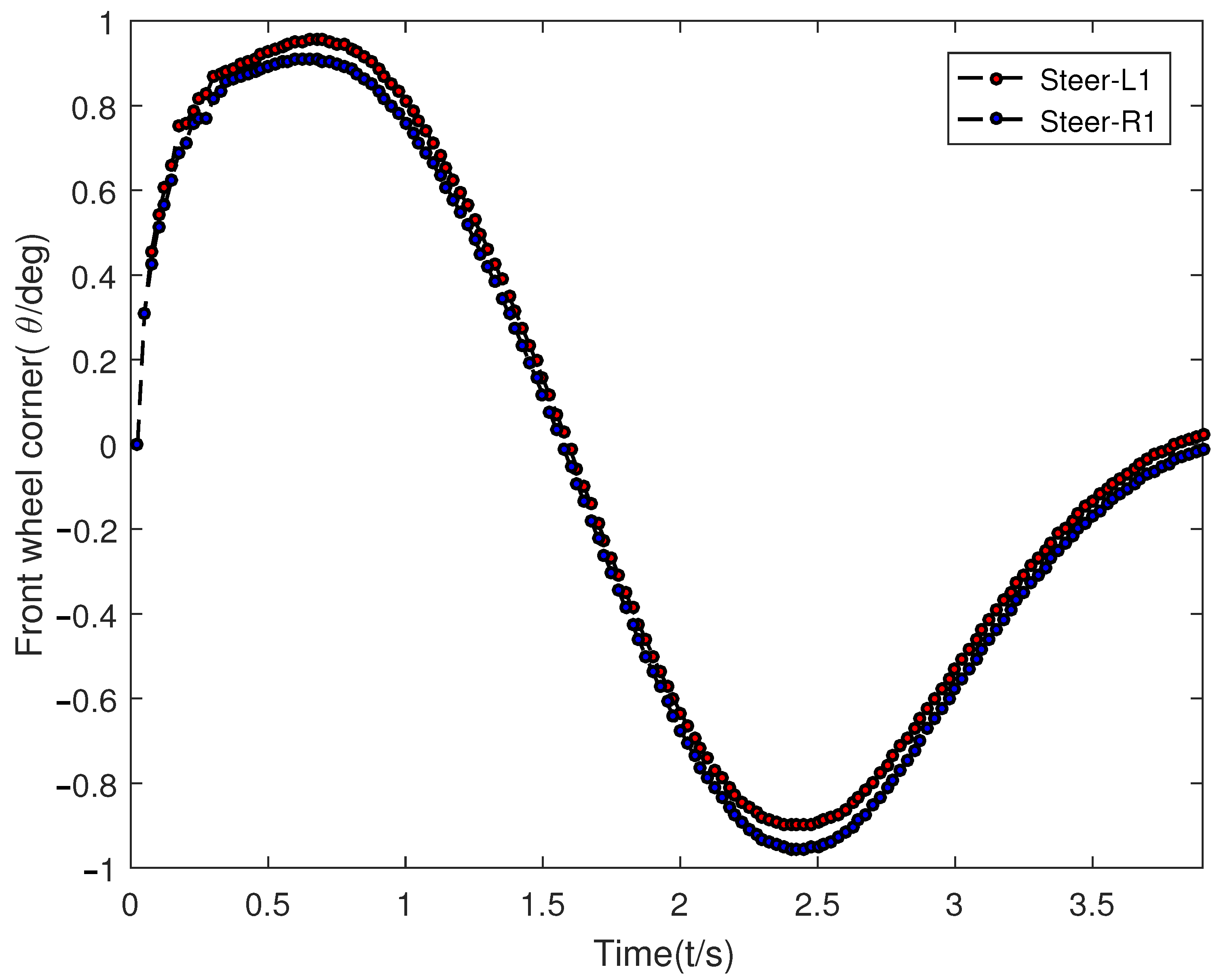
6.4. Trajectory Tracking Verification

Path tracking was conducted on a joint simulation platform consisting of Matlab and CarSim using a C-Class vehicle. The road surface was made of concrete with a friction coefficient of 0.9. The trajectory tracking results are shown below. Figure 19 depicts the displacement of the IV changing with time. The planned trajectory curvature is continuous, showing no abrupt alterations. As shown in Figure 20, in case of emergency, the maximum transverse acceleration of the second trajectory planning of the IV is less than 0.15 g. The value of acceleration is reasonable and satisfies the comfort criteria of the trajectory optimization function. Figure 21 shows the continuous change in the front wheel angle, which does not have any sudden changes and does not exceed the limit of the front wheel angle. The minor oscillation between 0 to 0.5 s can be attributed to the vehicle’s throttle opening initially being too small to meet the IV’s driving power needs. After 0.5 s, the vehicle’s driving returns to normal.
From Figure 19, Figure 20 and Figure 21, it can be observed that the planned trajectory curve adequately fulfills the requirements of the IV lane change. Both the transverse acceleration and the yaw rate fall within acceptable boundaries, ensuring high vehicle comfort and stability. The trajectory tracking error is kept within a certain range to ensure that the traceability of the trajectory is satisfied.

7. Discussion on Limitations and Future Enhancements

While the proposed autonomous lane change strategy leveraging V2V communication shows promising results, there are several potential shortcomings that warrant further investigation.
One limitation of the current method is its reliance on the availability and reliability of V2V communication. In environments where V2V infrastructure is not fully developed or where communication signals are weak, the effectiveness of the strategy may be compromised. Future work could explore hybrid approaches that integrate V2V data with other sensor inputs such as LiDAR or camera systems to enhance robustness.
Another area for improvement is the computational complexity associated with real-time trajectory planning using quintic polynomials and particle swarm optimization. While these methods provide high accuracy, they may not be suitable for all real-time applications, especially in highly dynamic traffic scenarios. Future research could focus on optimizing these algorithms for faster computation or on developing alternative methods that balance accuracy and computational efficiency.
Additionally, the current model assumes ideal conditions for vehicle dynamics and environmental factors. Real-world driving conditions can introduce uncertainties that affect the performance of the lane-change strategy. Incorporating uncertainty modeling and robust control techniques could improve the adaptability of the system to varying conditions.
Finally, extensive testing in diverse traffic environments is necessary in order to validate the generalizability of the proposed method. Future studies should include scenarios with mixed traffic, varying road conditions, and different vehicle types to ensure the strategy’s applicability across a wide range of situations.
By addressing these limitations and exploring these avenues for enhancement, we aim to refine the proposed method and contribute to the development of more reliable and efficient autonomous driving systems.

8. Conclusions

This study introduces an autonomous lane change strategy based on V2V communication that addresses key challenges such as discomfort and extended lane change times. The proposed method enhances the protective function of vehicles by ensuring safer and more efficient lane changes through real-time data exchange and decision-making. The strategy was validated using a combination of simulation software and real vehicle tests, confirming its viability. However, certain limitations remain, particularly in mixed traffic flows. The following conclusions summarize our findings and their implications for the development of IVs:
  • The integration of fuzzy logic theory with real-time vehicle-to-vehicle communication allows for a robust lane change decision model. This model accurately reflects lane change intentions and enhances vehicle safety by dynamically adjusting to surrounding traffic conditions. The protective function is enhanced by reducing the likelihood of collisions through informed decision-making processes.
  • The trajectory planning approach utilizing quintic polynomials and particle swarm optimization optimizes lane change timing and path smoothness, contributing to technical support for IV development by providing a framework for real-time trajectory adjustments based on dynamic traffic data. The proposed method’s application in practice can improve traffic flow and reduce congestion by enabling smoother and more predictable lane changes.
  • While our simulation and testing scenarios were not exhaustive, they provide a foundation for future research. Expanding the range of scenarios to include variable speeds and mixed traffic conditions will further enhance the model’s applicability. Establishing specific thresholds and safety margins will be crucial for practical implementation, where IVs need to safely navigate complex real-world environments.
Overall, this research provides technical support for the advancement of intelligent vehicles by offering a scalable and adaptable lane change strategy that can be integrated into existing vehicle systems. The findings have practical implications for improving road safety and traffic efficiency in increasingly automated transportation networks.

Author Contributions

Conceptualization, C.H., Q.Z. and W.J.; methodology, W.J. and Q.Z.; software, J.L.; validation, C.H., W.J., J.W., Q.Z. and J.L.; formal analysis, J.G.; investigation, J.L.; resources, W.J.; data curation, W.J. and J.W.; writing—original draft preparation, C.H.; writing—review and editing, W.J.; visualization, J.L.; supervision, J.G. and J.W.; project administration, C.H.; funding acquisition, C.H. and Q.Z. All authors have read and agreed to the published version of the manuscript.

Funding

This research was funded by the Key Project of Science and Technology Research Program of Chongqing Education Commission of China (No.KJZD-K202201203), the Science and Technology Research Program of Chongqing Municipal Education Commission (No. KJQN202301258), the Scientific Research Project of Wanzhou (No. wzstc20230315), and the Doctoral “Through Train” Scientific Research Project of Wanzhou (No. wzstc20230418).

Data Availability Statement

The original contributions presented in the study are included in the article, further inquiries can be directed to the corresponding author.

Conflicts of Interest

Jiang Guo is an employee of Chengdu Tangyuan Electric Co., Ltd. Qiankun Zhang is an employee of China Information Technology Designing and Consulting Institute Co., Ltd. The paper reflects the views of the scientists, and not the company.

Abbreviations

The following abbreviations are used in this manuscript:
IVIntelligent Vehicle
ITSIntelligent Transportation System
RNNRecurrent Neural Network
RFRandom Forest
V2XVehicle-to-Everything
DQNDeep Q-Network
IoVInternet of Vehicles
SVMSupport Vector Machine

References

  1. Claussmann, L.; Revilloud, M.; Gruyer, D.; Glaser, S. A Review of Motion Planning for Highway Autonomous Driving. IEEE Trans. Intell. Transp. Syst. 2020, 21, 1826–1848. [Google Scholar] [CrossRef]
  2. Huang, Y.; Du, J.; Yang, Z.; Zhou, Z.; Zhang, L.; Chen, H. A Survey on Trajectory-Prediction Methods for Autonomous Driving. IEEE Trans. Intell. Veh. 2022, 7, 652–674. [Google Scholar] [CrossRef]
  3. Feng, Z.; Song, W.; Fu, M.; Yang, Y.; Wang, M. Decision-Making and Path Planning for Highway Autonomous Driving Based on Spatio-Temporal Lane-Change Gaps. IEEE Syst. J. 2022, 16, 3249–3259. [Google Scholar] [CrossRef]
  4. Li, S.; Wei, C.; Wang, Y. Combining Decision Making and Trajectory Planning for Lane Changing Using Deep Reinforcement Learning. IEEE Trans. Intell. Transp. Syst. 2022, 23, 16110–16136. [Google Scholar] [CrossRef]
  5. Wiseman, Y. Real-time monitoring of traffic congestions. In Proceedings of the 2017 IEEE International Conference on Electro Information Technology (EIT), Lincoln, NE, USA, 14–17 May 2017; Volume 9, pp. 501–505. [Google Scholar]
  6. Li, L.; Zhao, W.; Xu, C.; Wang, C.; Chen, Q.; Dai, S. Lane-Change Intention Inference Based on RNN for Autonomous Driving on Highways. IEEE Trans. Veh. Technol. 2021, 70, 5499–5510. [Google Scholar] [CrossRef]
  7. Zhang, J.; Chang, C.; Zeng, X.; Li, L. Multi-Agent DRL-Based Lane Change with Right-of-Way Collaboration Awareness. IEEE Trans. Intell. Transp. Syst. 2023, 24, 854–869. [Google Scholar] [CrossRef]
  8. Li, M.; Zhang, J.; Li, W.; Yin, T.; Chen, W.; Du, L.; Yan, X.; Liu, H. Improved Taillight Detection Model for Intelligent Vehicle Lane-Change Decision-Making Based on YOLOv8. World Electr. Veh. J. 2024, 15, 369. [Google Scholar] [CrossRef]
  9. Zheng, L.; Liu, W. A Comprehensive Investigation of Lane-Changing Risk Recognition Framework of Multi-Vehicle Type Considering Key Features Based on Vehicles’ Trajectory Data. Electronics 2024, 13, 1097. [Google Scholar] [CrossRef]
  10. Wang, Q.; Ayalew, B.; Weiskircher, T. Predictive Maneuver Planning for an Autonomous Vehicle in Public Highway Traffic. IEEE Trans. Intell. Transp. Syst. 2019, 20, 1303–1315. [Google Scholar] [CrossRef]
  11. Tang, X.; Huang, B.; Liu, T.; Lin, X. Highway Decision-Making and Motion Planning for Autonomous Driving via Soft Actor-Critic. IEEE Trans. Veh. Technol. 2022, 71, 4706–4717. [Google Scholar] [CrossRef]
  12. Suh, J.; Chae, H.; Yi, K. Stochastic Model-Predictive Control for Lane Change Decision of Automated Driving Vehicles. IEEE Trans. Veh. Technol. 2018, 67, 4771–4782. [Google Scholar] [CrossRef]
  13. Rasekhipour, Y.; Khajepour, A.; Chen, S.-K.; Litkouhi, B. A Potential Field-Based Model Predictive Path-Planning Controller for Autonomous Road Vehicles. IEEE Trans. Intell. Transp. Syst. 2017, 18, 1255–1267. [Google Scholar] [CrossRef]
  14. Sun, Y.; Zhang, C.; Sun, P.; Liu, C. Safe and smooth motion planning for Mecanum-Wheeled robot using improved RRT and cubic spline. Arabian J. Sci. Eng. 2020, 45, 3075–3090. [Google Scholar] [CrossRef]
  15. Sheng, Z.; Liu, L.; Xue, S.; Zhao, D.; Jiang, M.; Li, D. A Cooperation-Aware Lane Change Method for Automated Vehicles. IEEE Trans. Intell. Transp. Syst. 2023, 24, 3236–3251. [Google Scholar] [CrossRef]
  16. Zhao, H.; Wu, H.; Lu, N.; Zhan, X.; Xu, E.; Yuan, Q. Lane Changing in a Vehicle-to-Everything Environment: Research on a Vehicle Lane-Changing Model in the Tunnel Area by Considering the Influence of Brightness and Noise under a Vehicle-to-Everything Environment. IEEE Intell. Transp. Syst. Mag. 2023, 15, 225–237. [Google Scholar] [CrossRef]
  17. Chen, N.; Arem, B.V.; Wang, M. Hierarchical Optimal Maneuver Planning and Trajectory Control at On-Ramps with Multiple Mainstream Lanes. IEEE Trans. Intell. Transp. Syst. 2022, 23, 18889–18902. [Google Scholar] [CrossRef]
  18. Diao, D.; Zhang, D.; Liang, W.; Gaudiot, J. A Novel Spatial-Temporal Multi-Scale Alignment Graph Neural Network Security Model for Vehicles Prediction. IEEE Trans. Intell. Transp. Syst. 2023, 24, 904–914. [Google Scholar] [CrossRef]
  19. Dong, C.; Chen, Y.; Wang, H.; Ni, D.; Shi, X.; Lyu, K. An Evolutionary Learning Framework of Lane-Changing Control for Autonomous Vehicles at Freeway Off-Ramps. IEEE Trans. Veh. Technol. 2023, 72, 1611–1628. [Google Scholar] [CrossRef]
  20. Hang, P.; Lv, C.; Huang, C.; Cai, J.; Hu, Z.; Xing, Y. An Integrated Framework of Decision Making and Motion Planning for Autonomous Vehicles Considering Social Behaviors. IEEE Trans. Veh. Technol. 2020, 69, 14458–14469. [Google Scholar] [CrossRef]
  21. Daoud, M.A.; Mehrez, M.W.; Rayside, D.; Melek, W.W. Simultaneous Feasible Local Planning and Path-Following Control for Autonomous Driving. IEEE Trans. Intell. Transp. Syst. 2022, 23, 16358–16370. [Google Scholar] [CrossRef]
  22. Peng, T.; Liu, X.; Fang, R.; Zhang, R.; Pang, Y.; Wang, T.; Tong, Y. Lane-change path planning and control method for self-driving articulated trucks. J. Intell. Connected Veh. 2020, 3, 49–66. [Google Scholar] [CrossRef]
  23. Benciolini, T.; Wollherr, D.; Leibold, M. Non-Conservative Trajectory Planning for Automated Vehicles by Estimating Intentions of Dynamic Obstacles. IEEE Trans. Intell. Veh. 2023, 8, 2463–2481. [Google Scholar] [CrossRef]
  24. Chen, L.-W.; Wang, G.-L. Risk-Aware and Collision-Preventive Cooperative Fleet Cruise Control Based on Vehicular Sensor Networks. IEEE Trans. Syst. Man Cybern. Syst. 2022, 52, 179–191. [Google Scholar] [CrossRef]
  25. Lee, S.; Oh, J.; Kim, M.; Lim, M.; Yun, K.; Yun, H.; Kim, C.; Lee, J. A Study on Reducing Traffic Congestion in the Roadside Unit for Autonomous Vehicles Using BSM and PVD. World Electr. Veh. J. 2024, 15, 117. [Google Scholar] [CrossRef]
  26. Sharma, O.; Sahoo, N.C.; Puhan, N.B. Dynamic Planning of Optimally Safe Lane-change Trajectory for Autonomous Driving on Multi-lane Highways Using a Fuzzy Logic-based Collision Estimator. ACM J. Auton. Transp. Syst. 2024, 1, 4. [Google Scholar] [CrossRef]
  27. Huang, J.; Long, Y.; Zhao, X. Driver Glance Behavior Modeling Based on Semi-Supervised Clustering and Piecewise Aggregate Representation. IEEE Trans. Intell. Transp. Syst. 2022, 23, 8396–8411. [Google Scholar] [CrossRef]
  28. Gangopadhyay, B.; Soora, H.; Dasgupta, P. Hierarchical Program-Triggered Reinforcement Learning Agents for Automated Driving. Trans. Intell. Transp. Syst. 2022, 23, 10902–10911. [Google Scholar] [CrossRef]
  29. Goldman, R.W. Development of a Rollover-Warning Device for Road Vehicles; The Pennsylvania State University: University Park, PA, USA, 2001; pp. 1–156. [Google Scholar]
  30. Tan, Z.; Wei, J.; Dai, N. Real-time Dynamic Trajectory Planning for Intelligent Vehicles Based on Quintic Polynomial. In Proceedings of the 2022 IEEE 21st International Conference on Ubiquitous Computing and Communications (IUCC/CIT/DSCI/SmartCNS), Chongqing, China, 19–21 December 2022; pp. 51–56. [Google Scholar]
Figure 1. Network architecture of IVs.
Wevj 15 00403 g001
Figure 2. Autonomous lane change framework based on V2X.
Wevj 15 00403 g002
Figure 3. Lane-change scenarios in connected vehicle environment.
Wevj 15 00403 g003
Figure 4. Typical lane-change scenario.
Wevj 15 00403 g004
Figure 5. Diagram of vehicle lane change in the current lane.
Wevj 15 00403 g005
Figure 6. Diagram of the current lane vehicle lane change.
Wevj 15 00403 g006
Figure 7. Velocity retention factor membership function.
Wevj 15 00403 g007
Figure 8. Distance-keeping factor membership function.
Wevj 15 00403 g008
Figure 9. Lane-change intention membership function.
Wevj 15 00403 g009
Figure 10. Free lane-change simulation environment.
Wevj 15 00403 g010
Figure 11. Speed of the vehicle in front of the IV.
Wevj 15 00403 g011
Figure 12. Information obtained by V2X.
Wevj 15 00403 g012
Figure 13. Co-simulation.
Wevj 15 00403 g013
Figure 14. Willingness to change lanes.
Wevj 15 00403 g014
Figure 15. Lane-change trajectory cluster.
Wevj 15 00403 g015
Figure 16. Trajectory optimization evaluation function.
Wevj 15 00403 g016
Figure 17. Impact of ε 1 / ε 2 .
Wevj 15 00403 g017
Figure 18. Real-time trajectory planning based on V2X.
Wevj 15 00403 g018
Figure 19. Vehicle location.
Wevj 15 00403 g019
Figure 20. Acceleration.
Wevj 15 00403 g020
Figure 21. Front wheel angle.
Wevj 15 00403 g021
Table 1. Specific parameters.
NotationDescriptionValue
C-ClassModel of this vehicleAITO 9
μ Pavement adhesion coefficient0.9
S c ( 0 , 1 ) The Longitudinal distance between C 0 and C 1 35 m
S c ( 0 , 3 ) The Longitudinal distance between C 0 and C 3 40 m
S c ( 0 , 4 ) The initial distance between C 0 and C 4 50 m
v 0 The speed of the C 0 20 m/s
v 3 The speed of the C 3 18 m/s
v 4 The speed of the C 4 22 m/s
dLane width3.5 m
Disclaimer/Publisher’s Note: The statements, opinions and data contained in all publications are solely those of the individual author(s) and contributor(s) and not of MDPI and/or the editor(s). MDPI and/or the editor(s) disclaim responsibility for any injury to people or property resulting from any ideas, methods, instructions or products referred to in the content.

