Article

Permanent Magnet Assisted Synchronous Reluctance Motor for Subway Trains

by
Vladimir Dmitrievskii
1,
Vadim Kazakbaev
1,
Vladimir Prakht
1,* and
Alecksey Anuchin
2
1
Department of Electrical Engineering, Ural Federal University, 620002 Yekaterinburg, Russia
2
Department of Electric Drives, Moscow Power Engineering Institute, 111250 Moscow, Russia
*
Author to whom correspondence should be addressed.
World Electr. Veh. J. 2024, 15(9), 417; https://doi.org/10.3390/wevj15090417
Submission received: 16 August 2024 / Revised: 7 September 2024 / Accepted: 10 September 2024 / Published: 13 September 2024

Abstract

:
With the growing demand and projected shortage of rare earth elements in the near future, the urgent task of developing energy-efficient electrical equipment with less dependence on rare earth magnets has become paramount. The use of permanent magnet-assisted synchronous reluctance motors (PMaSynRMs), which reduce the consumption of rare earth magnets, can help solve this problem. This article presents a theoretical analysis of the characteristics of PMaSynRM in a subway train drive. Options with rare earth and ferrite magnets are considered. Optimization of the motor designs considering the train movement cycle is carried out using the Nelder-Mead method. Characteristics of the motors, such as losses, torque ripple, and inverter power rating, as well as the mass and cost of active materials, are compared.

1. Introduction

Subway traction drives typically use traditional induction motors. However, some industry leaders have begun using synchronous motors in new subway trains. For example, permanent magnet synchronous motors from Alstom [1] and Siemens [2], Toshiba [3], or the synchronous reluctance motor from Mitsubishi Electric [4].
Note that permanent magnet synchronous motors (PMSMs) have a smaller mass compared to induction motors, which is very important for traction drives. In addition, PMSMs have a smaller rotor weight than that of induction motors. This is especially important in subway drives, as it allows to increase the service life of bearings and increase the interval between maintenance of the bearing unit. Additionally, the use of PMSMs instead of induction motors allows to significantly reduce electrical losses and heating.
Permanent magnet-assisted synchronous reluctance motors (PMaSynRMs) are comparable in performance to internal magnet synchronous motors (IPMs) [5,6], requiring substantially fewer rare earth permanent magnets [7,8], or using inexpensive ferrite magnets instead of rare-earth ones [9,10]. Since the shortage of rare-earth permanent magnets is predicted to increase in the near future [11,12], replacing IPMs with PMaSynRMs in a number of applications, such as electric vehicles [6], is becoming promising. There are quite a lot of examples in the literature comparing different PMaSynRM configurations for various applications.
Thus, in [13], a comparison of the characteristics of a synchronous reluctance motor (SynRM) without permanent magnets and a ferrite-assisted SynRM (FaSynRM) is presented. The effect of using a hybrid star-delta winding for both designs is also discussed. It is shown that among the motors under consideration, the FaSynRM with star-delta winding has the highest torque capacity and the widest constant power speed range (CPSR) of approximately 3.
Article [14] presents a comparison between a rare-earth assisted SynRM (REaSynRM) and a hybrid RE/FaSynRM in a passenger vehicle drive with a CPSR of 3. It is shown that the FaSynRM has better energy efficiency, greater rotor strength, and provides a higher output power at speeds above nominal.
Article [15] presents a theoretical comparison of the performance of an IPM and a PMaSynRM in a passenger car drive with CPSR of 3.5:1. The study concludes that the PMaSynRM is very close in performance to the IPM, while significantly reducing active material costs and demonstrating reduced maximum rotor operating temperature.
However, the prospects for using PMaSynRMs in subway train drives have not yet been widely discussed in the literature. There are known projects using SynRMs without permanent magnets in a subway train drive [4]. Meanwhile, PMaSynRMs can also be promising in this application since they also reduce/eliminate the need for RE while being more compact and requiring an inverter of a lower rating.
This article presents a study of the characteristics of PMaSynRM in a subway train drive. In this case, both REaSynRM and FaSynRM designs are considered. The optimal design results for the REaSynRM are presented in this paper. The characteristics of the FaSynRM are adapted from the authors’ previous study [16]. The characteristics of the considered motors are compared, such as power losses, torque ripple, and inverter power, as well as the mass and cost of active materials. The motor optimization criteria are losses in the operating cycle of a metro train, maximum motor current, torque ripple, rotor mass, and permanent magnet mass. The mass of the rotor is considered since it affects the service life of the bearings. Since rare-earth permanent magnets are the most expensive material, the mass of rare-earth permanent magnets is included in the optimization criteria to reduce the cost of active materials.
The contribution of this paper is the theoretical comparison of REaSynRM and FaSynRM in subway drives, considering the preliminary optimization of their losses in the subway train motion cycle. For this purpose, the REaSynRM parameterization presented in the article was proposed.
The use of the population-free Nelder–Mead method can significantly reduce computational costs when considering a relatively large number of operating points of the motion cycle during the optimization process.
As a result of optimization, such a reduction in the mass of rare-earth magnets in the REaSynRM is achieved that their price is approximately equal to the price of ferrite magnets in the FaSynRM.

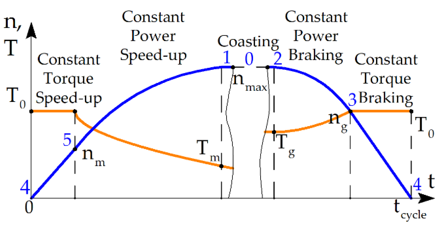
2. Considering the Train Movement Cycle in the Motor Optimization

When designing and optimizing a traction motor, it is important to consider the characteristics and operating conditions of the vehicle for which this motor is intended. In the simplest case, designers consider the characteristics of the motor at maximum torque and maximum speed. To increase energy savings, it is important to consider the time diagram of load parameters during the driving cycle [17,18]. However, load conditions (operating mode, shaft torque, and rotational speed) usually vary greatly during the operating cycle, making the selection of a single equivalent point representing multiple operating points not entirely relevant. One solution to this problem is to consider during optimization the points of the driving cycle that join different stages of movement [19,20] and carry out optimization at these points. The trapezoidal quadrature formula can be used to estimate the average values [21].
Table 1 shows six equivalent points at which the subway train motor is optimized. These six equivalent operating points are derived from the following. When moving from station to station, the train goes through stages, shown in Figure 1 and in Table 1. The blue numbers in this figure correspond to the various operating points shown in Table 1:
(1)
Acceleration while maintaining a constant torque T0 = 1240 N∙m to a speed nm = 1427 rpm (plot sections 4–5);
(2)
Acceleration with constant power up to speed nmax = 4280 rpm (sections 5–1);
(3)
Movement by inertia at approximately constant speed (sections 1–2); the model does not take into account friction, and the speed at this stage is assumed to be exactly constant.
(4)
Braking from speed nmax to speed ng = 2854 rpm with a constant power (sections 2–3);
(5)
Braking with torque T0 = 1240 N∙m to the stop (sections 3–4).
To calculate the weight coefficients wi of the equivalent points, the diagram presented in Figure 2 is used. In this figure, the numbers of the various operating points from Table 2 are indicated in blue font. It shows the points of the braking (generator) mode to the left of the ordinate axis. To the right of the ordinate are the points of the motor mode. Point 0 on the ordinate axis is necessary to consider losses in the motor when moving by inertia (losses in steel from the flux of permanent magnets and mechanical losses), which is important because of the longest duration of this stage. If coasting takes up 50% of the time required to travel between stations, integrating the speed shows that coasting takes up 63.3% of the total distance.
These weighting factors are specifically defined as follows:
wex0 = 1/2; wexi = wi/2, i = 1, 2, 3, 4, 5.
The calculation of weights wi is described in more detail in [21]. The average loss over the driving cycle, denoted as <Ploss>, is calculated using the formula:
<Ploss> = ∑(wexi ∙ Ploss i),
where Ploss i represents the total loss at the i-th operating point.
The maximum available voltages Vi are given by the factors ki = Vi/VDCrated, where VDC rated is the nominal DC voltage of 750 V, are not the same at different operating points. When operating in generator or motor mode, the output voltage levels can be affected by various factors, such as voltage drop across the power switching device. To take this into account, different values of coefficient ki are used. The parameters k2, k4, and k5 are set to 0.97 to account for the voltage drop across the switches in these cases. k1 is set to 0.99, which reflects the increase in DC voltage in generator mode. At operating point 2 (generator mode), k2 can be selected more than in motor modes 1, 4, and 5 due to battery charge recovery.

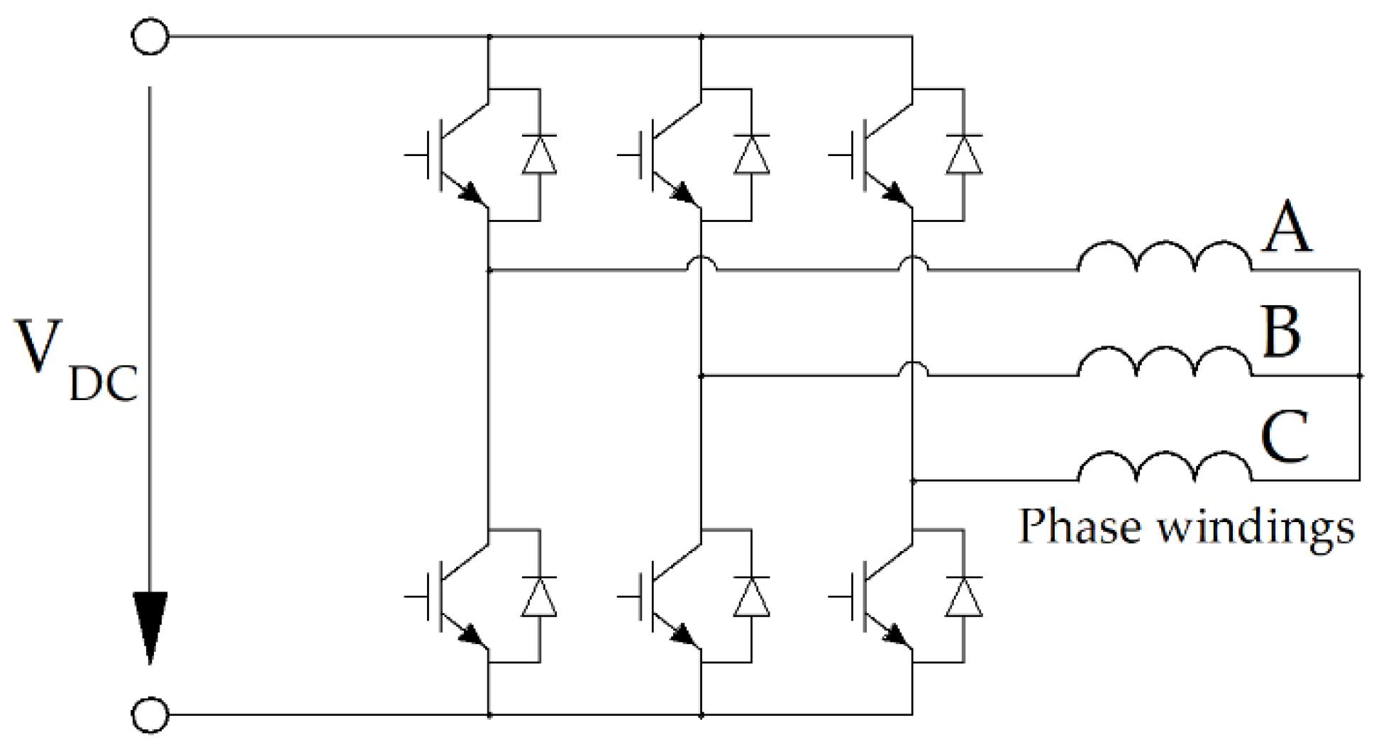
3. Main Design Features of the Motor and Traction Inverter

Figure 3 sketches of the REaSynRM and FaSynRM designs. Table 3 shows the main characteristics of the motor designs under consideration. It can be noted that in the case of the REaSynRM, the dimensions of the magnets are much smaller. While the thickness of the rotor flux barriers is not significantly less, they are narrowed in the magnet mounting segments.
Rare earth magnets have high residual flux density and coercivity. High coercivity allows the thickness of the magnets to be reduced without the risk of irreversible demagnetization. Due to their high residual flux density, rare earth magnets produce sufficient magnetic flux even when placed into a short section of magnetic barriers. Therefore, this study considers an REaSynRM rotor design in which fairly wide magnetic barriers have small narrowings to accommodate magnets. Sufficiently wide barriers make it possible to increase the magnetic anisotropy of the REaSynRM, and since the narrowing area is small, the magnetic anisotropy suffers only slightly.
The motor winding pattern is also visually represented in Figure 3 with letters from A to C to denote their sequential order. The inclusion of a minus sign in Figure 3 indicates a reversal in the current direction within a winding layer. Both designs of PMaSynRM under consideration have 8 poles, 48 slots, and 3 phases. The number of slots per pole and phase is equal to q = 48/(8 × 3) = 2.
PMaSynRMs with different numbers of flux barriers can have high performance [23]. For the PMaSynRM in this study, a rather large number of 4 was chosen, since it is known that further increasing the number of barriers does not lead to a significant increase in the performance of SynRM and PMaSynRM but reduces their mechanical strength and complicates their manufacturing [23].
The number of poles was chosen to be 8 for fair comparison with the results of other types of subway motors obtained in our previous studies [16,21].
Figure 4 depicts the power supply circuit for the traction motor, consisting of a conventional three-phase inverter designed for driving the armature winding of the PMaSynRM.

4. Objective Function and Optimization Procedure

In the process of optimizing the REaSynRM, the objective functions are minimized using the Nelder–Mead method. Although the Nelder–Mead method is a local optimization technique, it is particularly effective when initiated with well-chosen design parameters. A key benefit of this method over population-based algorithms, such as genetic algorithms and particle swarm optimization [24,25], lies in their significantly shorter computational time. This efficiency is especially important when optimizing many parameters or applying more complex optimization criteria, which is critical for improving the performance of electric machines across various operational conditions.
The motor’s external diameter is constrained by the dimensions of the car bogie, requiring compatibility with existing commercial induction motors. The optimization process primarily aims to minimize losses within the duty cycle, as illustrated in Figure 1, while also reducing the current rating for the power modules in the traction inverter. This dual focus not only enhances the overall efficiency of the machine but also contributes to cost reduction.
The objective functions of both machines are similar, although that of the FaSyRM has an additional penalty term in the case of demagnetization of the magnets. At the same time, due to the high coercivity of rare earth magnets, their demagnetization is not checked during the REaSynRM optimization. This check was carried out only for the REaSynRM final design.
The optimization goals for a subway train’s traction motor can be broken down into the following:
(1)
Firstly, there is a focus on minimizing the overall energy loss during operation, represented by the average loss factor <Ploss>. This value is derived from an assessment of losses across various operating points, with weights assigned according to their relative importance;
(2)
Secondly, the algorithm is aimed at reducing the peak current Iarm consumed by the motor armature winding at operating points 1–5, since minimizing this value allows for reducing the cost of power switches of the traction inverter at a given voltage limit. The power factor was not considered as an objective because it may take high values at high current values when the available voltage is not used enough;
(3)
It is also important to reduce the motor torque ripple TRi at operating points 1–5 to ensure a longer lifetime of the powertrain;
(4)
Minimizing the mass of the rotor Mrot (its magnetic core plus magnets). The rotor mass is added to the optimization function, since it affects the service life of the bearings, and an excessively large rotor mass will lead to unreasonably rapid failure of the bearings;
(5)
Minimizing the mass of the permanent magnets Mmag. The mass of permanent magnets is added to the optimization function, since permanent magnets are the most expensive material in the magnetic core, and their excessive use will lead to an unjustified increase in the cost of the machine.
The Nelder–Mead method, also known as the downhill simplex algorithm, is an unconstrained optimization technique, meaning it does not directly enforce constraints on variable parameters. However, as designs approach infeasibility, the objective function naturally increases, discouraging unfeasible solutions.
The objective function representing the above-described goals has the following form:
F = ln ( < P l o s s > ) + 0.7 ln ( max ( I a r m i ) ) + + 0.1 ln ( max ( T R i ) ) + 0.2 ln ( M r o t ) + 0.2 ln ( M m a g ) .
The weight coefficients used in Equations (3) and (4) (specifically, 1, 0.7, 0.1, 0.2, and 0.2) are applied to represent the relative importance of various optimization objectives. These values reflect the priorities assigned to each objective based on the authors’ extensive experience in designing similar machines. For instance, the coefficient of 0.7 indicates that a 1% reduction in maximum current is considered equivalent to a 0.7% decrease in average loss, illustrating the balance between different performance metrics within the optimization process.
Relatively less importance is attributed to the goal of minimizing torque ripple. Similarly, the constants 0.2 and 0.2 reflect the values of the goals minimizing the rotor and magnet masses.
These values reflect the approximate relative priorities assigned to each optimization goal, based on the author’s extensive experience in designing similar machines.
The optimization process for the REaSynRM involves minimizing losses even during coasting mode, where the motor is turned off, as illustrated in Figure 1. Despite the motor being turned off, losses generated by permanent magnets within the magnetic core do not disappear completely. This is particularly significant because the motor spends a considerable amount of time in this phase during the operational cycle.
The number of turns in the armature winding, denoted as Nsec, is selected so that VDC rated = max(Vi/ki) [26]. A crucial aspect of electric motor development is the recognition of the discrete nature of certain parameters, such as the number of turns Nsec in the armature winding coil and the standardized dimensions of the rectangular wire’s width and height, as specified in [21]. However, this study diverges from treating these values strictly as discrete, allowing them to take positive real values. This approach provides a more unbiased evaluation. While technological limitations may necessitate adjustments from the calculated optimal parameters (e.g., the number of turns in a coil must be an integer), the goal in practical electric machine implementation is to ensure that the actual parameters are as close as possible to the theoretical optimum.
The optimization process employs the Nelder–Mead method [27], using the fminsearch procedure, which is carried out within the MATLAB R2020b software environment, as detailed in [28]. The primary aim of the fminsearch(F, x0) procedure is to iteratively adjust the vector x, which represents the parameters of the electric machine, in order to minimize the objective function F. The vector x0 provides the initial values for these parameters, guiding the optimization process toward an optimal solution.
The calculations are performed based on a series of magnetostatic finite element model (FEM) problems. The losses are calculated in postprocessing. In FEM modeling, the properties of electric steel are taken into account conventionally by specifying the magnetization curve B(H) corresponding to the steel grade under consideration.
When calculating losses in the stator and rotor cores, it is taken into account that the magnetic flux is not sinusoidal, and a conventional method is used based on the magnitude of the flux density vector at various rotor positions calculated using FEM [29]. The calculation time for one machine candidate (including five operating points) on a laptop with a Core i5 4210U processor is 20 min.

5. REaSynRM Optimization Results

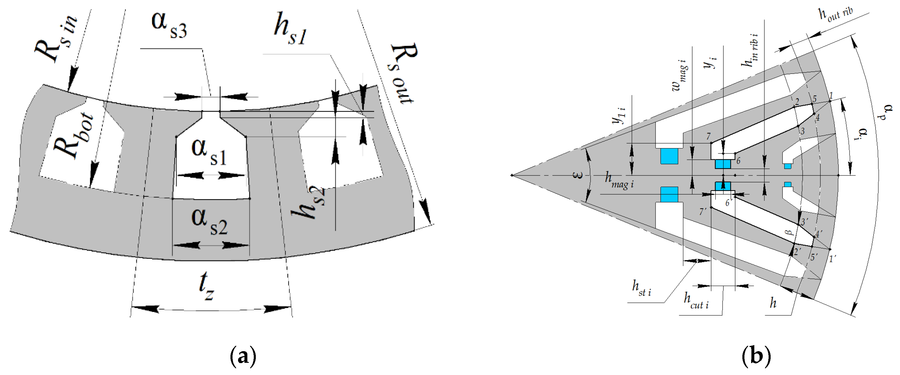
5.1. REaSynRM Optimization Parameters

Figure 5 shows a detailed visualization of the REaSynRM geometry, highlighting various critical parameters. The rotor of the REaSynRM features four distinct magnetic flux barriers per pole, which are numbered sequentially from 1 to 4, starting from the outermost barrier and progressing to the innermost one. This specific arrangement is depicted in Figure 5b. To maintain the rotor’s structural integrity, internal ribs are strategically placed at the midpoint of each flux barrier, with their thicknesses denoted as hin rib i, where iii corresponds to the barrier number (1, 2, 3, or 4). Additionally, all external ribs situated near the air gap are assumed to share uniform thicknesses, labeled hout rib. This configuration ensures both magnetic performance and mechanical stability within the rotor design.
The rotor surface is demarcated with key reference points that play a pivotal role in defining the barrier geometry. Let us consider one flux barrier with its reference points. Points 1 and 1′ are located at an angular distance αi from the symmetry axis of the barrier.
The points situated farther from the rotor surface at a distance h, specifically labeled as 2, 3, 2′, and 3′, are separated by an angular distance β from one another.
A circular demarcation referred to as 455′4′ sets the barrier ends at the distance of the outer ribs’ thickness hout rib from the outer rotor cylinder.
Lines 66′ and 77′ are perpendicular to the axes of symmetry. Unlike the internal rotor barriers, the outermost barrier has point 3 coinciding with point 6 and point 3′ coinciding with point 6′. The term hst i (i = 1, 2, 3) denotes the steel thicknesses from the given barrier to another one. The distances between lines 66′ and 77′ are denoted as hcut i, and the distances between points 6, 6′, and 7, 7′ are 2yi and 2y1i, respectively (i = 1, 2, 3, 4). Thus, the geometry of the rotor is determined by a lot of parameters.
To simplify the optimization process and reduce the calculation time, the number of variables to be adjusted is reduced by introducing new parameters. These newly introduced parameters are linked to the previously mentioned parameters of individual magnetic barriers by means of new specific dependencies, thereby simplifying the overall optimization procedure while maintaining accuracy:
αi = a + b(4 − i), i = 1, 2, 3, 4;
y1i = yic, i = 1, 2, 3;
yi + 1 = y1ig, i = 1, 2, 3, 4;
hcut i = acut + bcut (i − 1), i = 1, 2, 3, 4;
hst i = ast + bst (i − 1), i = 1, 2, 3.
These new rotor parameters a, b, c, g, acut, bcut, ast, and bst, defined by Equation (4), do not have geometric meaning. They are varied during optimization instead of the geometric parameters of individual barriers, which makes it possible to reduce the total number of optimization parameters. For the innermost (fourth) barrier, the angular distance ε between 7 and 7 is fixed during the optimization. Therefore, y14 is not determined by (5).
Additionally, the magnet thickness ratio (hmag i/hcut i) and the magnet width ratio (wmag i/yi) were assumed to be identical for all barriers. The parameter a in (5) is fixed during optimization to prevent the angular position of the fourth flux barrier α4 from increasing too much and avoiding unfeasible geometries.
Figure 5a illustrates the geometric parameters of the stator. The stator slot width ratio is αs1s2 assumed to be fixed.
During optimization, variable parameters also encompass current control angles at operating points 1, 2, 3, and 4. Fixed parameters of the REaSynRM are detailed in Table 4, while Table 5 outlines parameters subject to optimization.

5.2. REaSynRM Optimization Results

Table 6 presents a comparative overview of the initial and refined designs of the REaSynRM, showing their distinctive characteristics.
During the open-circuit coasting phase, the voltage at the motor terminals registers a transformation from 273 V in the initial configuration to 274 V in the postoptimization one, which is much less than VDC rated in both cases. Notably, the concentration of magnetic loss density in this phase predominantly resides within the stator magnetic core, with a reduction from 1.67 kW to 0.8 kW during the optimization.
In addition to that, Figure 6 showcases the REaSynRM geometry and flux density amplitude in operational points 0–5 detailed in Table 1. Meanwhile, Figure 7 presents a visual comparison of the geometry and flux density amplitude after the REaSynRM optimization.
Furthermore, Figure 8 delves into the picture of the demagnetizing field encompassing the region of permanent magnets on the rotor, which does not exceed 8.1 kOe. Figure 9 shows the REaSynRM torque ripple and cogging torque waveforms calculated by FEA.
The significant advantage of PMaSynRM, in comparison with IPM, is that the emergency short circuit mode of a PMaSynRM does not pose danger in terms of unacceptable current levels, overheating, or fire of the winding. In this case, there is also no risk of irreversible demagnetization. To confirm this, the asymptotic short circuit mode at infinite speed is calculated. In this case, the magnetic fluxes through the phase windings are zero, and the current value is determined by Lenz’s rule.
Figure 10 shows 2D plots of flux density and demagnetizing force in the permanent magnet region for the short circuit. Figure 11 shows the voltage and current waveforms for this case. The RMS value of the short-circuit current is 250 A, and its amplitude is 350 A, which is much less than the operating current amplitude, which is in the range of 445–896 A depending on the load point (see Table 6). The short circuit winding loss is 1.09 kW. The demagnetizing field does not exceed 3.3 kOe. These values are significantly less than underload. The magnetic flux of magnets in short-circuit mode is closed through sections of magnetic barriers unoccupied by magnets. In addition, the winding does not completely block the flux through the stator yoke due to slot leakage.
By comparing the performance of the REaSynRM before and after optimization, several key observations can be made about how changes implemented during the optimization process affected its performance:
(1)
The average losses after optimization were reduced by 100% × (11.11 − 7.63)/11.11 = 31.3%;
(2)
The core loss during the train coasting decreases by 1.67/0.8 = 2.1 times;
(3)
The maximum current consumption by the motor from the traction inverter decreased by 100% × (1395 − 896)/1395 = 35.7%;
(4)
The maximum torque ripple decreased by 33.2 − 15.3 = 17.9%;
(5)
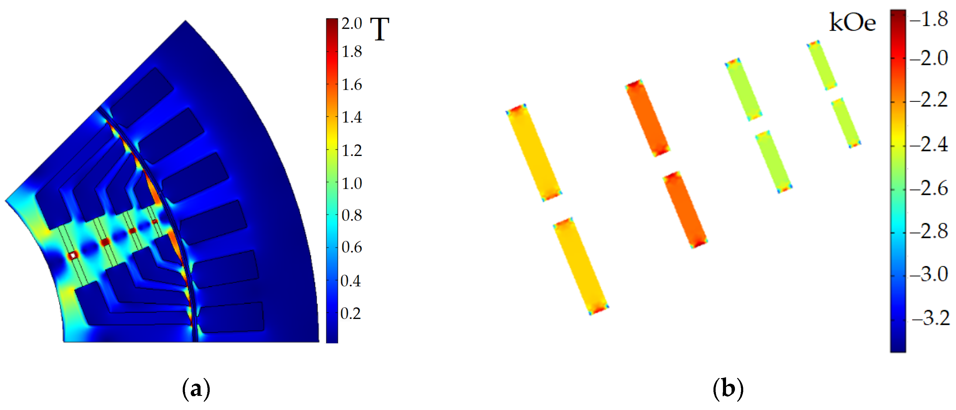
In the emergency short-circuit mode, the loss in the winding is (1.29 − 1.09)/1.29 = 15.5% less than in operating point 1 (high-speed motor mode), in which the loss is significantly less than in the full torque operating point, and the demagnetizing force is 8.1/3.3 = 2.5 times less.

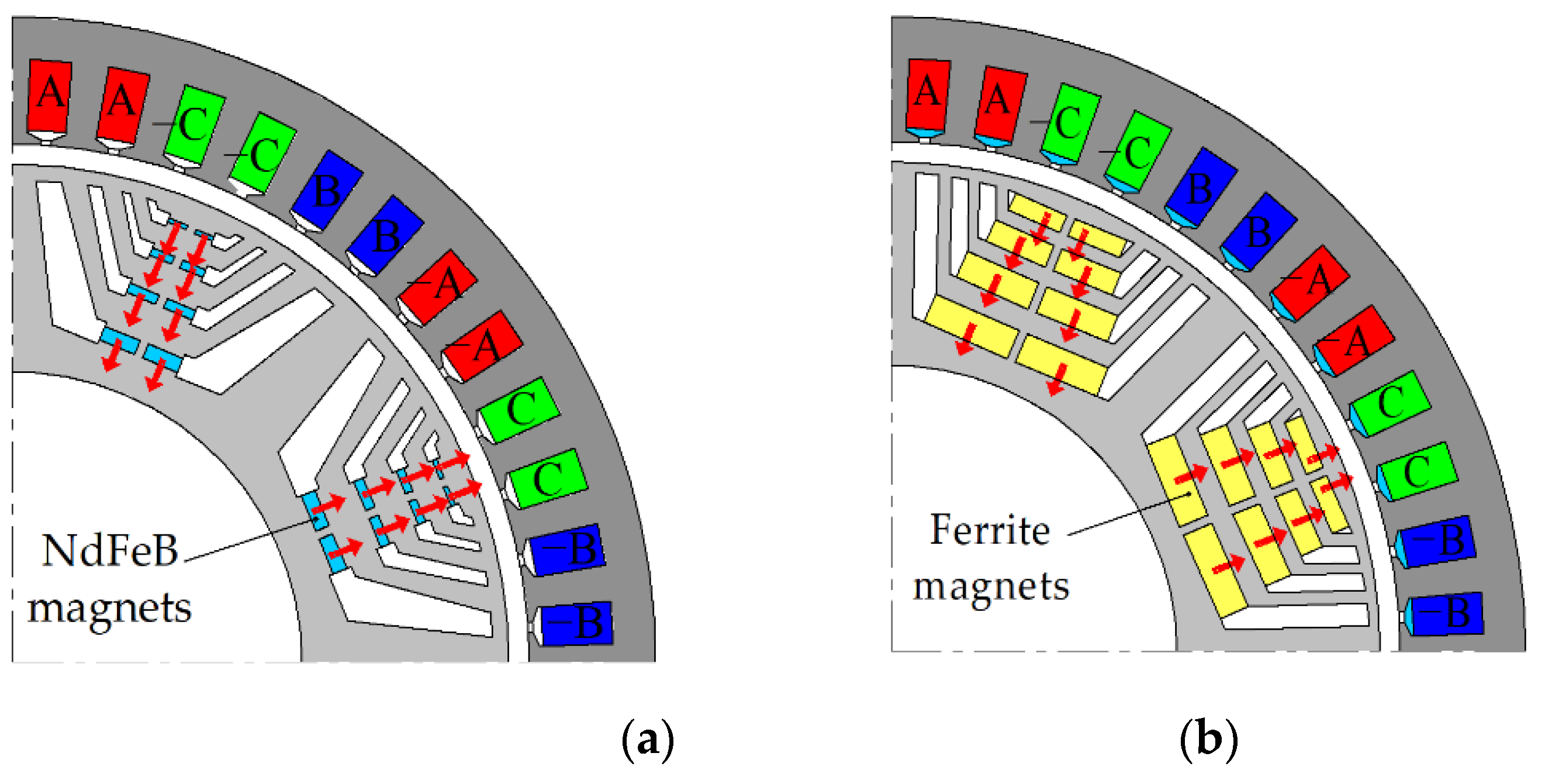
6. Performance Comparison of the REaSynRM and FaSynRM

This section compares the REaSynRM characteristics obtained in this study with the FaSynRM characteristics obtained in our previous study [16]. Table 7 and Table 8 compare the performance characteristics of FaSynRM and REaSynRM in the subway driving cycle. The optimized characteristics of FaSynRM are adopted from [16]. The optimized characteristics of the REaSynRM are taken from Table 6. The comparative analysis presented in Table 9 briefly illustrates the differences in weight, size, and cost of the active materials.
Comparing the characteristics of the FaSynRM and REaSynRM with the same outer diameter presented in Table 7, Table 8 and Table 9, we can draw the following conclusions:
(1)
The selected length of the REaSynRM, excluding the winding end parts, is shorter than that of the FaSynRM by (24 − 20)/24 = 17%, while the torque density and efficiency are close to those of the FaSynRM [16];
(2)
In this application, the average loss of the REaSynRM is 100% × (7.63 − 7.40)/7.63 = 3.0% greater than that of the FaSynRM;
(3)
The maximum armature current for the REaSynRM is 100% × (896 − 839)/896 = 6.4% greater than for the FaSynRM;
(4)
The mass of the REaSynRM rotor is 100% × (98.4 − 64.4)/98.4 = 34.5% less than that of the FaSynRM. This will ensure a longer service life of the bearings in the case of the REaSynRM;
(5)
Due to the full use of the higher potential of rare earth magnets, the mass of the magnets in the REaSynRM is reduced by 6.4 times compared to the FaSynRM. As a result, the cost of rare-earth magnets is only (393.7 − 369.2)/393.7 = 6.2% higher than the cost of ferrites in the FaSynRM, while a ratio of their prices per kg of 126.6/18.46 = 6.9 times;
(6)
The total mass of the REaSynRM active materials is 100% × (241 − 206.9)/241= 14.1% less than that of the FaSynRM;
(7)
In comparison to the FaSynRM, the REasSynRM incurs a 100% × (847.7 − 818.2)/847.7 = 3.5% increase in total material costs. This suggests that there is no significant increase in the cost of the REaSynRM, which is achieved by reducing the mass of the magnets compared to the FaSynRM with the reasonable use of this small amount of rare-earth magnets.

7. Conclusions

This paper discusses the optimal design of the permanent magnet-assisted synchronous reluctance motor (PMaSynRM) with rare earth magnets (REaSynRM) for subway train drive. Its performance is also compared with a SynRM with ferrite magnets (FaSynRM). Both motors have the same outer diameter.
The optimization of these machines is carried out considering the dynamic cycle of the train’s movement. To make this process more computationally efficient, the Nelder–Mead method is employed. During each iteration of the optimization, the machine’s characteristics are calculated at just six specific operating points. By using quadrature formulas, this approach allows for the comprehensive derivation of integral machine characteristics over the entire motion cycle, despite the limited number of points considered.
When parameterizing the REaSynRM rotor geometry for optimization, it must be considered that:
  • High coercivity helps reduce magnet thickness without the risk of irreversible demagnetization.
  • Due to their high remanent flux density, rare earth magnets produce sufficient magnetic flux even when placed into a short section of magnetic barriers.
Therefore, to optimize the REaSynRM, a geometry parameterization has been developed in which the dimensions of the magnets are selected independently of most of the dimensions of nonmagnetic barriers, specifying small narrowings of the barriers for placement of magnets.
The optimization goals involve a detailed approach aimed at reducing losses across the entire motion cycle of the train, minimizing peak current in the semiconductor inverter, and mitigating torque ripple effects. This thorough analysis seeks to offer a comprehensive comparison of the REaSynRM and FaSynRM designs, highlighting their respective advantages and disadvantages within the intricate field of subway train traction drives.
As a result of optimization, it is demonstrated that the possibility of developing the REaSynRM with comparable characteristics of the FaSynRM (losses are 3% more, maximum current is 6.4% more) with significantly improved weight and dimensions: the length of the motor excluding the winding end parts is reduced by (24 − 20)/24 = 17%, and the total mass of active materials is reduced by 14.1%.
Due to the full use of the potential of rare-earth magnets, the magnet mass is reduced by 6.4 times in the REaSynRM compared to the FaSynRM. As a result, the price of rare-earth magnets in the REaSynRM is only 6.2% higher than the price of ferrite magnets in the FaSynRM, with the ratio of their specific prices being 6.9 times. The total costs of the active materials of both machines are almost equal (by 100% (847.7 − 818.2)/847.7 = 3.5% higher for the REaSynRM). The REaSynRM also has a 34.5% lower rotor weight, which will ensure longer service life of the bearings.

Author Contributions

Conceptual approach, A.A., V.D. and V.P.; data curation, V.D. and V.K.; software, V.D. and V.P.; calculations and modeling, A.A., V.D., V.K. and V.P.; writing—original draft, A.A., V.D., V.K. and V.P.; visualization, V.D. and V.K.; review and editing, A.A., V.D., V.K. and V.P. All authors have read and agreed to the published version of the manuscript.

Funding

The research funding from the Ministry of Science and Higher Education of the Russian Federation (Ural Federal University Program of Development within the Priority-2030 Program) is gratefully acknowledged.

Data Availability Statement

The original contributions presented in the study are included in the article, further inquiries can be directed to the corresponding author.

Acknowledgments

The authors thank the editors and reviewers for carefully reading and providing constructive comments.

Conflicts of Interest

The authors declare no conflicts of interest.

References

  1. Railway Pro. Alstom Tests a New Train Traction System in China. Press Release. 29 May 2023. Available online: https://www.railwaypro.com/wp/alstom-tests-a-new-train-traction-system-in-china/ (accessed on 5 September 2024).
  2. Körner, O.; Schmidt, D.; Wetzel, W. Energy efficient propulsion technology based on permanent magnet synchronous motors. Eng. Veh. Technol. 2023, 121, 296–304. Available online: https://assets.new.siemens.com/siemens/assets/api/uuid:d699a038-d754-46d1-9c17-7241daa549ca/siemens-mobility-Energy-efficient-propulsion-technology-eb-technical-article-en-original..pdf (accessed on 5 September 2024).
  3. Toshiba Global. Permanent Magnet Synchronous Motor (PMSM). Supply Record. Available online: https://www.global.toshiba/ww/products-solutions/railway/rolling-stock/pmsm.html (accessed on 5 September 2024).
  4. Tokyo Metro Tested Synchronous Reluctance Traction Motors. Railvolution: The Professional On-Line Magazine of Rail Transport Worldwide. Available online: https://www.railvolution.net/news/tokyo-metro-tested-synchronous-reluctance-traction-motors (accessed on 5 September 2024).
  5. Wang, Y.; Bianchi, N.; Qu, R. Comparative Study of Non-Rare-Earth and Rare-Earth PM Motors for EV Applications. Energies 2022, 15, 2711. [Google Scholar] [CrossRef]
  6. Burress, T.; Campbell, S. Benchmarking EV and HEV power electronics and electric machines. In Proceedings of the 2013 IEEE Transportation Electrification Conference and Expo (ITEC), Detroit, MI, USA, 16–19 June 2013; pp. 1–6. [Google Scholar]
  7. Calvo, E.S.; Potoradi, D. Synchronous reluctance motors with and without permanent magnets for high performance low cost electrical drives. In Proceedings of the 2015 5th International Electric Drives Production Conference (EDPC), Nuremberg, Germany, 15–16 September 2015. [Google Scholar]
  8. Liu, Z.; Hu, Y.; Wu, J.; Zhang, B.; Feng, G. A Novel Modular Permanent Magnet-Assisted Synchronous Reluctance Motor. IEEE Access 2022, 9, 19947–19959. [Google Scholar] [CrossRef]
  9. Barcaro, M.; Pradella, T.; Furlan, I. Low-torque ripple design of a ferrite-assisted synchronous reluctance motor. IET Electr. Power Appl. 2016, 10, 319–329. [Google Scholar] [CrossRef]
  10. Pellegrino, G.; Jahns, T.M.; Bianchi, N.; Soong, W.L.; Cupertino, F. The Rediscovery of Synchronous Reluctance and Ferrite Permanent Magnet Motors: Tutorial Course Notes; Springer: New York, NY, USA, 2016; p. 136. [Google Scholar]
  11. McKinsey & Company. The Net-Zero Materials Transition: Implications for Global Supply Chains, Report. July 2023. Available online: https://www.mckinsey.com/industries/metals-and-mining/our-insights/the-net-zero-materials-transition-implications-for-global-supply-chains (accessed on 14 August 2024).
  12. Dong, S.; Li, W.; Chen, H.; Han, R. The status of Chinese permanent magnet industry and R&D activities. AIP Adv. 2017, 7, 1–17. [Google Scholar]
  13. Ibrahim, M.N.; Silwal, B.; Sergeant, P. Permanent Magnet-Assisted Synchronous Reluctance Motor Employing a Hybrid Star-Delta Winding for High Speed Applications. In Proceedings of the 2018 XIII International Conference on Electrical Machines (ICEM), Alexandroupoli, Greece, 3–6 September 2018. [Google Scholar]
  14. Li, Y.; Yang, H.; Lin, H.; Fang, S.; Wang, W. A Novel Magnet-Axis-Shifted Hybrid Permanent Magnet Machine for Electric Vehicle Applications. Energies 2019, 12, 641. [Google Scholar] [CrossRef]
  15. Liu, X.; Li, Y.; Liu, Z.; Ling, T.; Luo, Z. Analysis and design of a high power density permanent magnet-assisted synchronous reluctance machine with low-cost ferrite magnets for EVs/HEVs. COMPEL Int. J. Comput. Math. Electr. Electron. Eng. 2016, 35, 1949–1964. [Google Scholar] [CrossRef]
  16. Dmitrievskii, V.; Kazakbaev, V.; Prakht, V. Performance Comparison of Traction Synchronous Motors with Ferrite Magnets for a Subway Train: Reluctance versus Homopolar Variants. Appl. Sci. 2023, 13, 9988. [Google Scholar] [CrossRef]
  17. Wang, J.; Yuan, X.; Atallah, K. Design Optimization of a Surface-Mounted Permanent-Magnet Motor with Concentrated Windings for Electric Vehicle Applications. IEEE Trans. Veh. Technol. 2013, 62, 1053–1064. [Google Scholar] [CrossRef]
  18. Lacock, S.; du Plessis, A.A.; Booysen, M.J. Electric Vehicle Drivetrain Efficiency and the Multi-Speed Transmission Question. World Electr. Veh. J. 2023, 14, 342. [Google Scholar] [CrossRef]
  19. Guo, S.; Zhao, H.; Wang, Y.; Yin, X.; Qi, H.; Li, P.; Lin, Z. A Design Technique of Traction Motor for Efficiency Improvement Based on Multiobjective Optimization. World Electr. Veh. J. 2021, 12, 260. [Google Scholar] [CrossRef]
  20. Ramakrishnan, K.; Stipetic, S.; Gobbi, M.; Mastinu, G. Optimal Sizing of Traction Motors Using Scalable Electric Machine Model. IEEE Trans. Transp. Electrif. 2018, 4, 314–321. [Google Scholar] [CrossRef]
  21. Dmitrievskii, V.; Prakht, V.; Kazakbaev, V.; Anuchin, A. Design Optimization of the Magnet-Free Synchronous Homopolar Motor of a Subway Train. Appl. Sci. 2022, 12, 12647. [Google Scholar] [CrossRef]
  22. Dmitrievskii, V.; Prakht, V.; Kazakbaev, V. Design Optimization of a Synchronous Homopolar Motor with Ferrite Magnets for Subway Train. Mathematics 2023, 11, 589. [Google Scholar] [CrossRef]
  23. Moghaddam, R.R. Synchronous Reluctance Machine (SynRM) Design. Thesis for the Degree of Master of Science in Engineering, Royal Institute of Technology, Department of Electrical Engineering, Electrical Machines and Power Electronics, Stockholm. 2007. Available online: https://www.diva-portal.org/smash/get/diva2:753114/FULLTEXT01.pdf (accessed on 14 August 2024).
  24. Wogi, L.; Thelkar, A.; Tahiro, T.; Ayana, T.; Urooj, S.; Larguech, S. Particle Swarm Optimization Based Optimal Design of Six-Phase Induction Motor for Electric Propulsion of Submarines. Energies 2022, 15, 2994. [Google Scholar] [CrossRef]
  25. Kang, Y.-R.; Son, J.-C.; Lim, D.-K. Optimal Design of IPMSM for Fuel Cell Electric Vehicles Using Autotuning Elliptical Niching Genetic Algorithm. IEEE Access 2020, 8, 117405–117412. [Google Scholar] [CrossRef]
  26. Prakht, V.; Dmitrievskii, V.; Kazakbaev, V.; Anuchin, A. Comparative Study of Electrically Excited Conventional and Homopolar Synchronous Motors for the Traction Drive of a Mining Dump Truck Operating in a Wide Speed Range in Field-Weakening Region. Mathematics 2022, 10, 3364. [Google Scholar] [CrossRef]
  27. Lagarias, J.C.; Reeds, J.A.; Wright, M.H.; Wright, P.E. Convergence properties of the Nelder–Mead simplex method in low dimensions. SIAM J. Optim. 1998, 9, 112–147. [Google Scholar] [CrossRef]
  28. The MathWorks, Inc. Find Minimum of Unconstrained Multivariable Function Using Derivative-Free Method. MATLAB Documentation. 1994–2023. Available online: https://www.mathworks.com/help/matlab/ref/fminsearch.html (accessed on 14 August 2024).
  29. Prakht, V.; Dmitrievskii, V.; Kazakbaev, V. Mathematical modeling ultra premium efficiency (IE5 class) PM assisted synchronous reluctance motor with ferrite magnets. In Proceedings of the 2018 25th International Workshop on Electric Drives: Optimization in Control of Electric Drives (IWED), Moscow, Russia, 31 January–2 February 2018; pp. 1–6. [Google Scholar] [CrossRef]
  30. ChenYang NdFeB Magnets. Price List of Standard Block Magnets. Available online: http://www.ndfebmagnets.de/CY-PriceList-NdFeB-Block.pdf (accessed on 14 August 2024).
  31. IBSMagnet. Hard Ferrite Magnets, Product Information. 2020. Available online: https://ibsmagnet.com/products/dauermagnete/hartferrit.php (accessed on 14 August 2024).
Figure 1. Graphical representation of the rotational speed (blue line) and torque (orange line) generated by the traction motor of a subway train as it moves from station to station. Based on the diagram from Ref. [22].
Wevj 15 00417 g001
Figure 2. Requirements for the torque-speed characteristic of the traction motor for the subway train, on which the numbers of the various operating points from Table 1 are indicated in blue font. Based on the diagram from Ref. [22].
Wevj 15 00417 g002
Figure 3. Motor design representation, 2-pole area, magnetization of the permanent magnets is marked with red arrows: (a) rare-earth-assisted synchronous reluctance motor (REaSynRM); (b) ferrite-assisted synchronous reluctance motor (FaSynRM).
Wevj 15 00417 g003
Figure 4. Subway train traction motor inverter. Armature phase windings are indicated with A, B, and C.
Wevj 15 00417 g004
Figure 5. REaSynRM parameters: (a) stator; (b) rotor.
Wevj 15 00417 g005
Figure 6. Cross-section of the REaSynRM before optimization, with the flux density magnitude at the saturation limit (greater than 2 T) highlighted in white: (a) operating point 0; (b) operating point 1; (c) operating point 2; (d) operating point 3; (e) operating point 4; (f) operating point 5.
Wevj 15 00417 g006
Figure 7. Cross-section of the REaSynRM after optimization, with the flux density magnitude at the saturation limit (greater than 2 T) highlighted in white: (a) operating point 0; (b) operating point 1; (c) operating point 2; (d) operating point 3; (e) operating point 4; (f) operating point 5.
Wevj 15 00417 g007aWevj 15 00417 g007b
Figure 8. Demagnetizing field in the area of permanent magnets of the REaSynRM rotor: (a) before optimization; (b) after optimization in operation point 4.
Wevj 15 00417 g008
Figure 9. REaSynRM waveforms calculated using FEA: (a) torque ripple at operating point 1; (b) torque ripple at operating point 4; (c) cogging torque at coasting.
Wevj 15 00417 g009
Figure 10. REaSynRM plots at short circuit: (a) flux density modulus (T); (b) demagnetization field (kOe).
Wevj 15 00417 g010
Figure 11. REaSynRM waveforms in short circuit mode: (a) phase voltage; (b) phase current.
Wevj 15 00417 g011
Table 1. Operating cycle of the subway train drive.
StageStage NameDuration, s
4–5Acceleration with a constant torque6.9
5–1Acceleration with a constant power27.8
0Coasting at a steady speed57.3
2–3Deceleration with a constant power8.7
3–4Deceleration with a constant torque13.9
Table 2. Points highlighted from the operating cycle which are examined to ensure optimal performance and efficiency.
Operating Point, iOperating Point NameSpeed, rpmTorque, N∙mwikiwexi *
0Coasting mode; maximum speed42800--0.5
1Driving mode; maximum speed4280413.40.3630.970.181
2Braking mode; maximum speed4280826.90.0910.990.046
3Braking mode; changing from constant power to constant torque 285412400.1821.10.091
4Zero speed012400.1820.970.091
5Driving mode; changing from maximum torque to constant power142712400.1820.970.091
Note: * wexi represents the weight coefficient for the i-th operating point, which indicates the proportion of time that the i-th operating point occupies within the overall movement cycle.
Table 3. Design features of the PMaSynRMs.
ParameterREaSynRMFaSynRM [16]
Phase number3
Pole number8
Magnet gradeN40HY30H-2
Steel gradeM270-35A
Steel thickness, mm0.35
Stator slot number48
Number of the armature winding layers1
Number of the stator slots per pole and phase q2
Rotor flux barrier number per pole4
Table 4. Parameters of the motor that remain constant during the optimization process.
ParameterValue
Stator parameters
Machine length excluding winding end parts L, mm200
Stator outer radius Rs out, mm250
Stator parameter hs1, mm1
Stator parameter hs2, mm3
Stator slot thickness ratio αs1s21.05
Rotor parameters
Outer rotor ribs thickness hout rib, mm1
Inner rotor ribs thickness hin rib i, mm1.5; 2.5; 3.5; 4
Rotor parameter h, mm3
Rotor parameter ε0.8∙αp
Rotor parameter a0.4777∙αp
Remanent flux density of the PMs, T1.2
Relative magnetic conductivity of permanent magnets1.05
The geometric meaning of the parameters is shown in Figure 5; αp is the rotor pole pitch.
Table 5. Variable motor parameters.
ParameterInitial DesignOptimized Design
Stator parameters
Inner stator radius Rs in, m0.20.1834
Stator slot bottom radius Rbot, m0.230.2199
Stator slot thickness αs10.4 ∙ tz0.572 ∙ tz
Rotor parameters
ast, mm44.46
bst, mm11.22
acut, mm47.90
bcut, mm11.74
B0.0777 ∙ αp0.0762 ∙ αp
C1.071.125
G1.071.113
β, rad0.010.0201
Magnet’s thickness ratio, hmag,i/hcut,i0.50.257
Magnet’s width ratio, wmag,i/yi0.50.485
Other parameters
Air gap width δ, mm12.33
Current angle, electrical degrees50; 50; 50; 5064.3; 66.8; 59.7; 55.6
Note: The geometric meaning of the parameters is shown in Figure 5; tz is the stator slot pitch.
Table 6. REaSynRM performances before and after optimization.
ParameterBefore Optimization
Operating point, i12345
Rotational speed n, rpm42804280285401427
Amplitude of the armature phase current Iarm, A483876137713881395
Efficiency, %92.393.393.7092.4
Output mechanical power P2, kW185.3−370.6−370.60185.3
Torque, N∙m413827124001240
Input electrical power, kW200.7345.7347.311.3200.5
Mechanical loss, kW *3.553.551.0600.14
Armature copper loss, kW1.294.6711.3111.3111.31
Stator lamination loss, kW9.6815.099.9503.46
Rotor lamination loss, kW0.911.611.0200.26
Total loss, kW15.4224.9223.3511.3115.16
Rotational speed n, rpm42804280285401427
Average losses <Ploss>, kW11.11
Number of turns in armature winding1.75
Power factor0.830.750.6500.64
Line-to-line voltage amplitude Varm, V621.3757.5600.19.4307.6
Torque ripple, %31.632.633.233.233.2
ParameterAfter Optimization
Rotational speed n, rpm42804280285401427
Amplitude of the armature phase current Iarm, A445709896888894
Efficiency, %94.995.595.9095.0
Output mechanical power P2, kW185.3−370.6−370.60185.3
Torque, N∙m413827124001240
Input electrical power, kW195.2353.9355.57.0195.0
Mechanical loss, kW *3.553.551.0600.14
Armature copper loss, kW1.694.567.216.976.97
Stator lamination loss, kW4.117.756.5702.59
Rotor lamination loss, kW0.550.860.2700.06
Total loss, kW9.9016.7215.116.979.75
Average losses <Ploss>, kW7.63
Number of turns in armature winding2.77
Power factor0.860.790.7100.69
Line-to-line voltage amplitude Varm, V626.1757.5708.59.1365.9
Torque ripple, %17.817.814.315.315.3
Note: * It is assumed that mechanical loss increases proportionally to the cube of the speed, reaching a maximum value of 3.55 kW at nmax.
Table 7. Characteristics of the optimized FaSynRM.
ParameterOperating Point, i
012345
Rotational speed n, rpm428042804280285401427
Amplitude of the armature phase current Iarm, A0450693833832839
Efficiency η, % *-94.795.496.0095.3
Output mechanical power P2, kW−4.19185.3−370.6−370.60185.3
Torque T, N∙m0413.4826.9124012401240
Input electrical power P1, kW0195.6353.5355.96.2194.4
Mechanical loss Pmech, kW 3.553.553.551.0600.14
Armature copper loss Parm DC, kW01.764.446.376.226.22
Stator lamination loss Piron st, kW0.494.257.886.8902.70
Rotor lamination loss Piron rt, kW00.771.210.3300.07
Total loss Ploss, kW **4.0410.3317.0814.656.229.12
Average losses <Ploss>, kW7.40
Power factor-0.9100.79110.7690.735
Line-to-line voltage amplitude Varm, V-6217576659356
Torque ripple, %-1616111010
Maximum demagnetizing force, kOe 2.0
Note: * the PMaSynRM efficiency is calculated as η = P2/P1 = P2/(P2 + Ploss), where P1 is the active power in armature winding; P2 is the output (mechanical) power. ** The total loss for PMaSynRM is calculated as a sum of the following Ploss = Parm DC + Piron st + Piron rt + Pmech.
Table 8. Characteristics of the optimized REaSynRM.
ParameterOperating Point, i
012345
Rotational speed n, rpm428042804280285401427
Amplitude of the armature phase current Iarm, A0445709896888894
Efficiency η, % *-94.995.595.9095.0
Output mechanical power P2, kW−4.35185.3−370.6−370.60185.3
Torque T, N∙m0413827124001240
Input electrical power P1, kW0195.2353.9355.57.0195.0
Mechanical loss Pmech, kW 3.553.553.551.0600.14
Armature copper loss Parm DC, kW01.694.567.216.976.97
Stator lamination loss Piron st, kW0.794.117.756.5702.59
Rotor lamination loss Piron rt, kW0.10.550.860.2700.06
Total loss Ploss, kW **4.359.9016.7215.116.979.75
Average losses <Ploss>, kW7.63
Power factor-0.860.790.7100.69
Line-to-line voltage amplitude Varm, V-626.1757.5708.59.1365.9
Torque ripple, %-17.817.814.315.315.3
Maximum demagnetizing force, kOe 8.1
Note: * the PMaSynRM efficiency is calculated as η = P2/P1 = P2/(P2 + Ploss), where P1 is the active power in armature winding; P2 is the output (mechanical) power. ** The total loss for PMaSynRM is calculated as a sum of the following Ploss = Parm DC + Piron st + Piron rt + Pmech.
Table 9. Operating cycle points for the subway train drive considered in the optimization.
ParameterFaSynRMREaSynRM
Stator lamination mass, kg104.6100.8
Rotor lamination mass, kg78.461.3
Armature copper mass, kg3841.7
Magnets mass, kg203.11
Total rotor material mass, kg98.464.4
The total mass of the active materials, kg241206.9
Stator lamination cost, USD104.6100.8
Rotor lamination cost, USD78.461.3
Armature copper cost, USD266291.9
Magnets cost, USD369.2393.7
The total cost of the active materials, USD *818.2847.72
Total length of the stator lamination L, mm240200
Stator lamination outer diameter D, mm500500
Air gap, mm2.232.33
Note: * In conducting a material cost analysis of the traction motor variants, this study considered three types of materials: copper used in the motor windings (7 USD/kg); electrical steel used as the main material of the magnetic core (1 USD/kg); and two types of magnets (rare earth N40H, 126.6 USD/kg, and ferrite Y30H-2, 18.46 USD/kg). The specific prices associated with these materials are based on references [16,30,31], which provide an indication of the current market value of such materials.
Disclaimer/Publisher’s Note: The statements, opinions and data contained in all publications are solely those of the individual author(s) and contributor(s) and not of MDPI and/or the editor(s). MDPI and/or the editor(s) disclaim responsibility for any injury to people or property resulting from any ideas, methods, instructions or products referred to in the content.

