Article

A Study on the Design of a Fault-Tolerant Consequent-Pole Hybrid Excited Machine for Electric Vehicles

Nuclear Technology and Automation Engineering, Chengdu University of Technology, Chengdu 610059, China
*
Author to whom correspondence should be addressed.
World Electr. Veh. J. 2025, 16(3), 130; https://doi.org/10.3390/wevj16030130
Submission received: 12 January 2025 / Revised: 20 February 2025 / Accepted: 21 February 2025 / Published: 26 February 2025
(This article belongs to the Special Issue Electrical Motor Drives for Electric Vehicle)

Abstract

:
In this paper, a new fault-tolerant consequent-pole hybrid excited (FTCPHE) machine with toroidal winding (TW) is designed for electric vehicles (EVs). In this proposed machine, U-type permanent magnets (PMs) are adopted in the consequent-pole rotor with the sequence of PM–iron–PM–iron. The stator tooth placed in the stator is classified into two groups to achieve hybrid excitation. The TW is positioned on the stator yoke to achieve the simple structure and excellent fault-tolerant ability. First, the topology of this proposed FTCPHE machine with the TW is briefly introduced and compared to that with the traditional combined winding. Second, the operation principle, the magnetic circuit, and the design procedure of the FTCPHE machine are analyzed and illustrated. Third, several key structural parameters of the proposed FTCPHE machine are discussed and designed to improve electromagnetic performances. Next, some electromagnetic properties, including the flux distribution, the no-load back-EMF, the electromagnetic torque, the cogging torque, and the fault-tolerant ability, are discussed in detail. Finally, a prototype of this proposed FTCPHE machine is manufactured to validate the simulated results.

1. Introduction

Owing to high efficiency and torque density, PM machines have attracted much attention in the last two decades. They have already been used in many applications, such as EVs and flywheels [1,2,3]. In general, to improve output torque ability, the PM usages of PM machines are relatively high, which may result in high cost and long manufacturing process. Then, the speed range of the conventional PM machine is restricted due to the fixed PM excitation. Furthermore, the torque density is decreased and the toque ripple is enlarged significantly when a failure happens in the PM machines. Hence, hybrid excited PM (HEPM) machines are proposed in some existing research to increase PM utilization and flux-regulating capability [4]. According to the relative position between PMs and field windings (FWs), HEPM machines can be divided into two types: a brush HEPM machine and a brushless HEPM machine.
For the brush HEPM machine, both the PMs and the FWs are generally housed in the rotor, in which the FWs are usually injected with a DC. In [5], the typical structure of the series HEPM machine is exhibited, in which the flux paths generated by PMs and FWs are in series. To decrease the risk of the irreversible demagnetization, the parallel HEPM machine is proposed [6]. The iron core is adopted in this parallel HEPM machine to isolate PMs and FWs. In [7], the interior permanent magnet (IPM) machine is redesigned to achieve the hybrid excited effect. The simulated result indicates that the maximum speed of the IPM machine is five times higher than the rated speed. To improve PM utilization and power density, some V-type HEPM machines are introduced in [8,9], in which the FWs and the PMs are combined to work in the rotor. Compared to the conventional V-type IPM machines, these proposed HEPM machines exhibit stronger fault-tolerant ability and higher torque density [10]. However, the flux leakage of this V-type HEPM machine is relatively high.
Different from the brush counterparts, the electrical excitations of the brushless HEPM machines can be either DC currents or AC currents, and the PMs are generally placed on the stator. In [11], a hybrid-excitation flux-switching (HEFS) machine is proposed to improve speed range and fault-tolerant ability. For these HEFS machines, the hybrid excitation capabilities of the U-/E-/C-shaped stator core are discussed and compared [12], in which the efficiencies of them are in the range between 87% and 90%. The consequent-pole structure is also applied in the HEPM machine. In [13], an asymmetric consequent-pole hybrid excited flux reversal machine (AS-CP-HEFRM) is proposed. In the AS-CP-HEFRM, the PM excitation can be flexibly controlled by the FWs. However, the stator is quite crowded with FWs, PMs, and armature windings (AWs). To improve space utilization, the dual-stator HEPM machines are introduced and analyzed in some recent existing literature. In [14], series partitioned stator hybrid excited (PSHE) machines are proposed to achieve better power density. A parallel PSHE machine is introduced in [15]. The flux-regulating capability of the parallel PSHE machine is improved compared with the series counterpart. A partitioned stator field modulation machine with H-shape PM excitation (HPM-PSFMM) is proposed in [16] to achieve the low torque ripple, high torque density, low flux leakage, and low total harmonic distortion (THD), in which the torque ripple can be decreased to 4.94%. However, the robustness of this proposed machine is relatively low owing to the iron-piece rotor; thus, the speed range is limited. To solve the problem of crowded stator, a multi-phase brushless fault-tolerant hybrid-excitation (FTHE) motor is proposed in [17]. The armature coils are placed on the armature teeth of the stator, which are isolated by the fault-tolerant teeth. The FWs, the PMs, and the harmonic windings are designed in the rotor to achieve the hybrid excited effect. In [18], a new three-segment dual-stator permanent magnet machine is proposed, in which the AC hybrid excitation is adopted instead of the DC hybrid excitation. However, this machine topology is relatively complicated, which may result in the high manufacturing cost.
Furthermore, the reliability of these brush/brushless HEPM machines used for EVs should also be considered, which means that the fault-tolerant ability [17] of the HEPM machines should be improved. In [19], a PM machine is proposed for Mars Rover driving. The proposed machine employs the DC winding as the excitation backup of the PM to keep high electromagnetic performances under fault operations. In [20], a doubly salient HEPM machine with high fault-tolerant ability is introduced. The machine structure is simple. However, the torque density of this proposed machine is relatively low.
For HEPM machines applied for EVs, it should be emphasized that it is quite hard to achieve the balance among the efficiency, the flux-regulating ability, the torque/power density, and the structural simplicity for the HEPM machines. Then, due to the slip rings and iron-piece rotor, it is also hard to achieve good reliability for HEPM machines. Furthermore, a multi-phase structure is not discussed to improve the fault-tolerant ability of the HEPM machines in the existing literatures. Hence, in this paper, a new FTCPHE machine used for EVs and hybrid EVs (HEVs) is proposed to resolve the existing problems of brush/brushless HEPM machines. This proposed machine has four structural features. First, this proposed machine achieves the brushless hybrid excitation with a new unique harmonic field coupling effect. Second, the PMs and the FWs are respectively located in the rotor and the stator to achieve both high space utilization and excellent reliability. Third, the consequent-pole structure is adopted in the rotor to decrease PM usage without sacrificing torque density. Fourth, the TW is adopted in the FTCPHE machine to integrate the functions of AWs and FWs simultaneously to achieve low copper loss, high fault-tolerant ability, and structural simplicity.
This article is organized as follows. The typology of the FTCPHE machine with the TW is illustrated and compared to that with the conventional winding in Section 2. In Section 3, the main working principles and design methods of this machine are discussed and introduced. Then, some critical parameters of this proposed FTCPHE machine are analyzed. In Section 4, several electromagnetic properties, including flux density, no-load back-EMF, output ability, and fault-tolerant ability, are simulated by the finite element (FE) method. In Section 5, a prototype is manufactured to verify FE-predictions. Finally, some conclusions are drawn in Section 6.

2. Machine Topology

In this section, the topology features and the main working mechanisms of the proposed FTCPHE machine are analyzed in detail for better understanding.

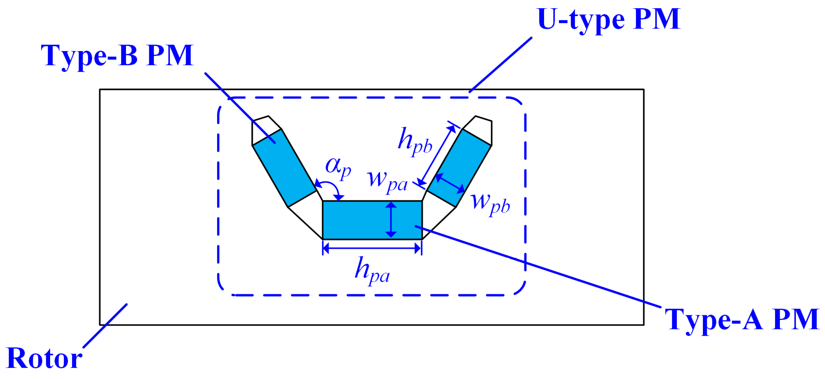
2.1. Topology Description

The 3D configuration of the proposed FTCPHE machine is illustrated in Figure 1a. The stator tooth is divided into two types, in which the main tooth is slightly larger in size than the supplementary tooth. The consequent-pole structure is employed in the rotor. The PMs in the rotor are designed as the U-type to achieve the stronger flux-focusing ability. All these U-type PMs are magnetized in the same polarity; thus, PM usage can be deceased significantly. In addition, two adjacent U-type PMs are isolated by one iron core. For the FTCPHE machine with the traditional winding, the stator winding is divided into the AW and the FW. The FW is installed on the supplementary tooth. The AW is a three-phase single-layer chain winding. The FW is injected with DC currents; thus, the electrical excitation field is static. It should be emphasized that the topology of the FTCPHE machine with the conventional combined winding is quite complicated, which may lead to high copper/iron loss and the overheating phenomenon. Compared with the traditional winding, the FTCPHE machine with the TW adopts only one set of windings, which can combine both the functions of the AW and the FW.
The winding connections of the conventional winding and the TW are illustrated in Figure 2. As shown in Figure 2a, the AW in the FTCPHE machine employs the conventional three-phase single-layer chain winding, in which the pole-pair number of the AW is one. Furthermore, only the AC current is injected in the AW. Then, the DC current is injected in the FW, in which the pole-pair number of the FW is six. According to the field modulation effect [21], the static flux generated by DC currents in FW can be modulated as the rotating flux in the air gap. In addition, the pole-pair number of the modulated rotating flux is changed, which is determined by the iron core quantity in the rotor and the pole-pair number of the FW [22]. The effective output torque can be produced if the modulated rotating flux is synchronous with the PM flux. However, the conventional winding suffers from some drawbacks. For example, if the volume of the end winding is increased, high copper loss and long axial length may occur as a result. In addition, the stator is crowded with two sets of windings (AW + FW), in which the manufacturing process becomes complicated. As shown in Figure 2b, the current input into the FTCPHE machine with the TW consists of two types. Taking Phase A as an example, due to the features of DC and AC, coils A11 and A12 are Sub-phase A with the forward DC, and coils A21 and A22 are Sub-phase A with the reverse DC. With the TW, all coils are isolated from each other. Hence, good magnetic and thermal isolation effects can be obtained to achieve the excellent fault-tolerant ability. According to AC/DC features, it can be found that the TW can completely replace the conventional winding from the electromagnetic perspective. Moreover, compared with conventional winding, the FTCPHE machine with the TW has a simpler winding structure, which can contribute to good heat dissipation ability, low manufacturing cost, and short processing cycle.

2.2. Operation Principle

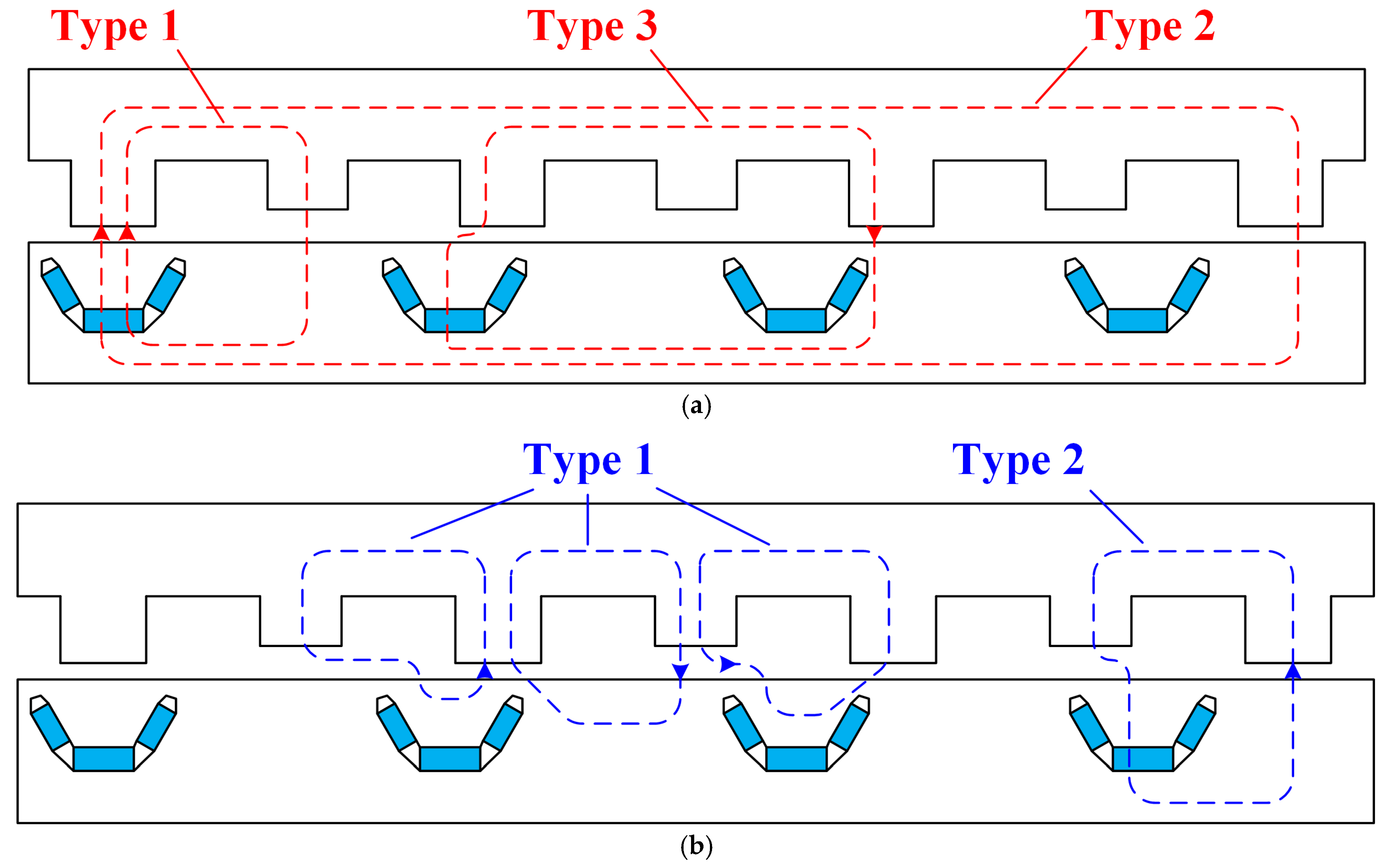
2.2.1. Magnetic Circuits

The specific path of the magnetic circuits of the proposed FTCPHE machine are illustrated in Figure 3. First, the fluxes of Circuit A are generated by U-type PMs, which maintain the same rotating speed with the rotor. Second, the fluxes of Circuit B are generated by the static exciting DC. In addition, Circuit A refers to the main fluxes used to generate electromagnetic torque. Circuit B is utilized to control the air-gap flux density. Based on the field modulation effect, it should be emphasized that hybrid excitation can be achieved between these two circuits by a suitable slot/pole combination. This is because the main static harmonic of Circuit B can be modulated into the rotating modulated harmonic by the iron core in the rotor, in which the modulated harmonic can rotate synchronously with the main harmonic of Circuit A. It should be noted that the directions and the amplitude of the air-gap flux can be regulated by the DC injected into FWs [21,22]; thus, the hybrid excitation can be achieved in the FTCPHE machine.
Based on the FE method, the distributions of the flux-densities generated by the PM and the DC can be obtained, as shown in Figure 4. Based on this figure, it can be found that the main component of the flux generated from the PM excitation is the harmonic with seven pole-pairs. Similarly, the main component of DC excitation is the sixth harmonic (six pole-pairs). Obviously, the analysis of the magnetic circuits in Figure 3 can be verified. Combining Circuit A, Circuit B, and the field modulation effect, it should be emphasized that the waveforms of the air-gap flux density generated from the PMs can be obviously influenced by the DC currents in the TW, which contributes to the feasibility of the operating principle proposed in this machine.

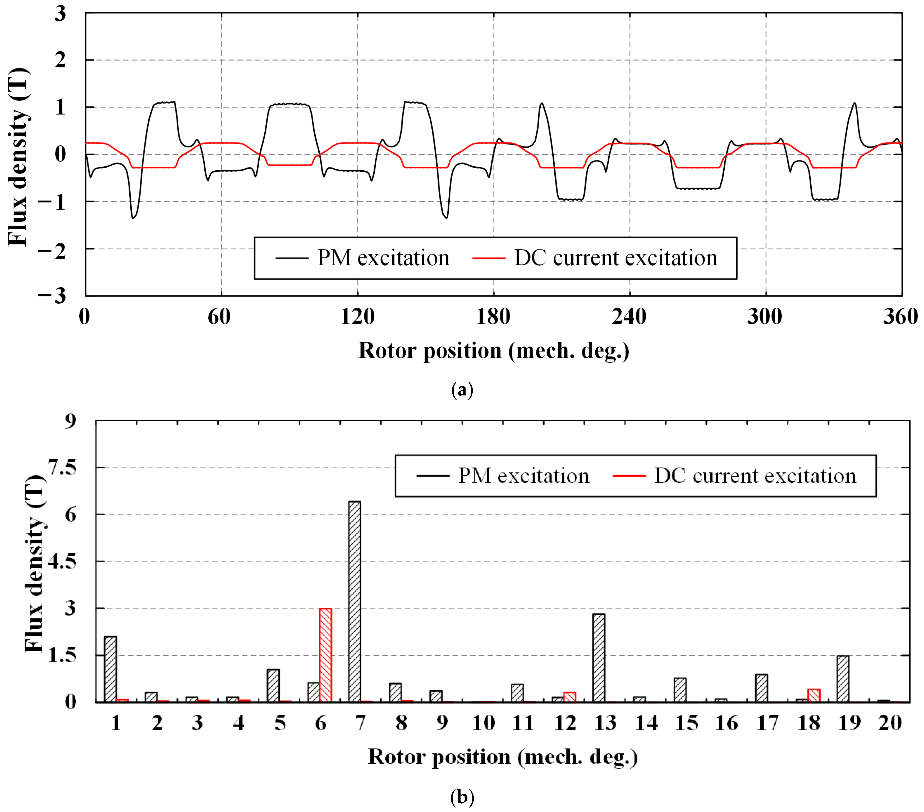
2.2.2. Field Modulation Effect

To achieve the hybrid excited effect, these two fluxes should be coupled in certain ways. Therefore, based on the features of the field modulation effect, several key parameters should satisfy
p ro = p a ± p d N p m = N i r o n = p ro = N i r o n + N p m 2
where pro, pa, and pd refer to the pole-pair numbers of the fundamental harmonics generated by the rotor, the armature current, and the DC current, and Npm and Niron refer to the U-type PM number and the iron core number. It should be emphasized that the harmonic field coupling effect depends on the relation among pole-pair numbers of the air-gap field harmonics. The static fluxes (Circuit B) generated by DCs cannot be utilized to generate output electromagnetic torque in the air gap directly. However, based on the field modulation effect, these static fluxes can be modulated into the rotating magnetic field by the iron cores. In addition, the modulated harmonic should be synchronized with the rotating harmonic produced by PMs. Hence, the pole-pair number pmo of the modulated harmonic can be expressed as
p m o = N iron ± p d
It should be noted that the pole-pair number of the modulated magnetic field should be equal to that of the magnetic field produced by the armature current. Then, to achieve the stable hybrid excitation, the modulated magnetic field should maintain in synchronization with the rotating magnetic field generated by the armature current.
For the FTCPHE machine with the TW, the current input into the TW consists of both DC and AC components. In other words, DC and AC currents can coexist in the TW simultaneously. Therefore, the current Ito(t) input into the FTCPHE machine with the TW can be deduced as
I t o t = I a m cos ω t + i 2 3 π ± I d f
where Iam and Idf refer to the amplitudes of AC and DC currents, i refers to the positive integer, ω refers to the current frequency.

3. Machine Design

The aims of the design of the FTCPHE machine are to improve the torque density and enlarge the speed range. Considering the processing difficulty, cycle and cost, the rated power of this proposed machine is set as 700 W.

3.1. Power and Torque Equation

For one-phase of the TW, which consists of four coils, the amplitude of the fundamental flux linkage ϕ can be deduced as [23]
Φ = 1 + ε k w l s D ro B g p ro
where kw refers to the winding factor, ls refers to the stack length, Dro refers to the diameter of the rotor, Bg refers to the fundamental air-gap flux density, ε refers to the flux-regulating factor, which is determined by the DC current. Accordingly, the amplitude E of the fundamental back-EMF can be deduced as
E = 1 + ε ω ro k w l s D ro B g N ph
where Nph refers to the coil turns, ωro refers to the rotor speed. Furthermore, the relation between the electric load Aam and the amplitude of the armature current Iam can be deduced as [24]
I am = 2 π D ro 2 m ph N ph A am
where mph refers to the phase number. Combing Equations (4)–(6), the power P and torque T of the proposed FTCPHE machine can be obtained
P = 2 4 1 + ε ω ro k w l s D ro 2 B g A a π cos γ T = 2 4 1 + ε k w l s D ro 2 B g A a π cos γ
where γ refers to the current angle. Owing to ε, the air-gap flux density is flexible. Therefore, the wide speed range and the high output torque of the FTCPHE machine can be analytically explained by Equation (7).

3.2. Slot/Pole Combination

Based on the working principles of this proposed FTCPHE machine, the number Qs of the slot should be the multiple of 2mphpak, in which k refers to the positive integer. This is because the slot number Qs is equal to the stator tooth number Zt. Therefore, the slot number Qs should be the sum of the main tooth number Zm and the supplementary tooth number Zs, in which Zm is equal to Zs. Combining Equation (1) and Figure 3a, the flow direction of the iron core is opposite to that of the PM. Therefore, the iron core can be considered as the iron pole [25], in which polarity of the iron pole is opposite to the PM pole. Then, it can be found that the rotor pole-pair number pro is equal to the U-type PM number Npm, which is different from the conventional PM machine. Furthermore, the pole-pair number pa maintains a significant difference with the pole-pair number pd of the DC field currents, as far as possible. It should be emphasized that the peak-to-peak value and the cycle of the cogging torques are determined by both the slot number Qs and rotor pole-pair number pro. For better utilization of fundamental harmonic [21,22], the slot number Qs should be close to double the rotor pole-pair number pro. Combining Equations (1) and (2), the slot/pole combination can be summarized as follow
Q s = 2 p r o ± 2 Q s 2 = Z t 2 = Z m = Z s = p d Q s = 2 m p h p a k p iron = p p m = N iron = N p m p ro = N p m = N iron
where piron and ppm refer to the iron pole number and the PM pole number. Therefore, the slot/pole combination of the proposed FTCPHE machine can be determined by Equation (8), in which the selected combination is 12/14. In addition, the remaining parameters are defined as: pro = piron = ppm = Niron = Npm = 7, pd = 6, pa = 1, Zm = Zs = 6, Zt = 12, mph = 3.

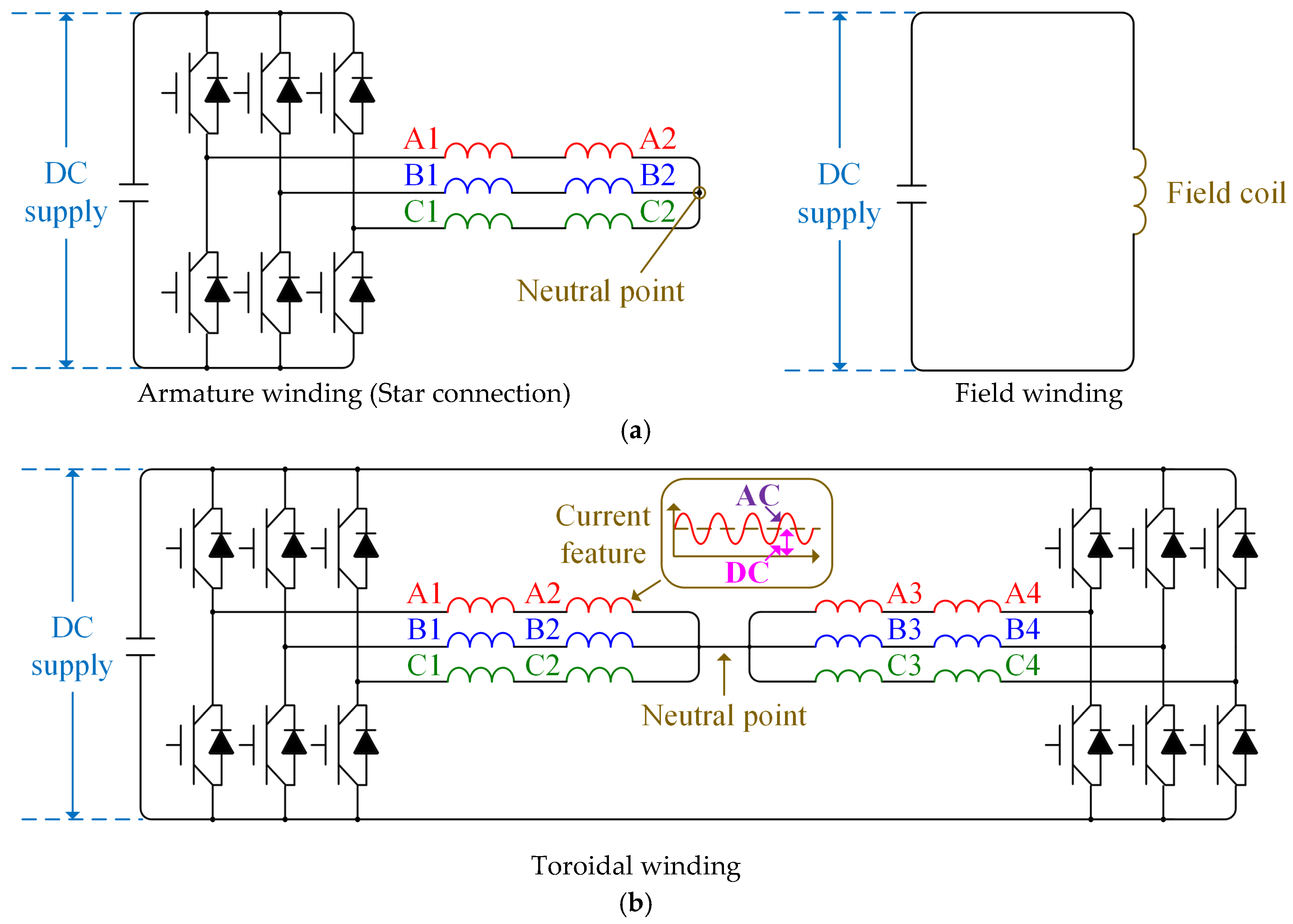
3.3. Winding Connection of Inverter

As shown in Figure 5a, the inverter used for the FTCPHE machine with the conventional winding is divided into two parts. Based on the traditional star connection shown in Figure 5a, it can be found that there is no DC current existed in the inverter. Therefore, the inverter in the FTCPHE machine can be regarded as the conventional three-phase system. Then, the field coil is powered by the DC supply directly. However, this structure may result in processing difficulty and high manufacturing cost. As shown in Figure 5b, due to the features of the TW, it should be noted that both the DC and the AC currents should pass through the neutral point, which is a significant difference from the conventional star winding. In addition, according to the features of the current direction, the structure of the three-phase winding of the TW can also be regarded as the six-phase (dual three-phase) winding in the control level.

3.4. Parameter Analysis

The structural parameters of the proposed FTCPHE machine should be further discussed for better electromagnetic performance. Therefore, in this section, several key dimension parameters of the FTCPHE machine are selected and divided into two types: stator parameters and rotor parameters.

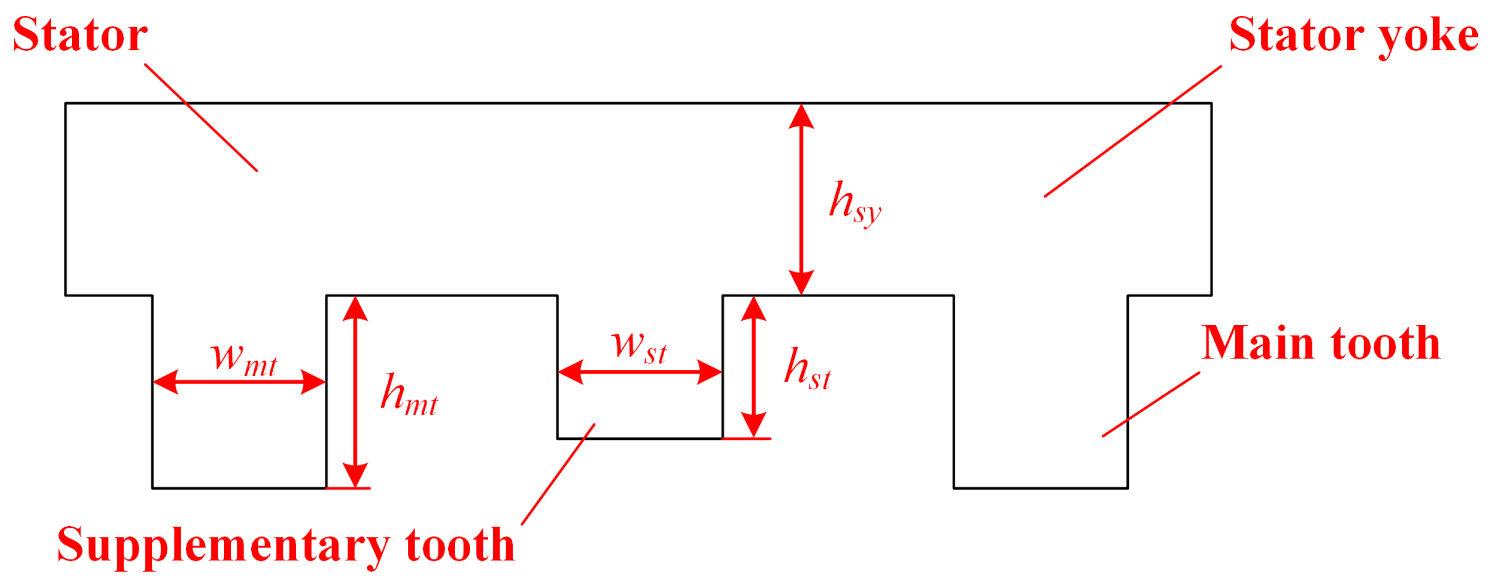
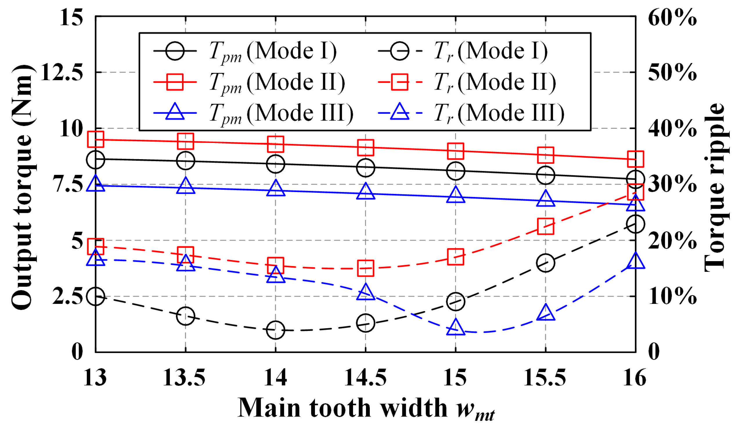
3.4.1. Stator Parameters

As shown in Figure 6, the critical stator parameters for the FTCPHE machine are the width ratio kwidth of the stator tooth, the height ratio khight of the stator tooth, the main tooth width wmt and the stator yoke thickness hsy. First, kwidth is defined as the ratio of the main tooth width wmt and the supplementary tooth width wst, and khight is defined as the ratio of the main tooth height hmt and the supplementary tooth height hst. Furthermore, kwidth and kheight can be expressed as
k width = w mt w st k height = h mt h st
In this section, the impacts of this structural parameter kwidth/kheight on the average output torque, the torque ripple Tr and the torque variation coefficient kt are discussed under the constant electric load. In addition, this coefficient kt can be expressed as
k t = T en T we T p m × 100 %
where Tpm refers to the output torque under only-PM state, Ten and Twe refer to the output torque under flux-enhancing and flux-weakening state, respectively. Second, the main tooth width wmt is also critical, because it is the main path for Circuit A and B. In this section, the variations of the electromagnetic torques against the main tooth width wmt are analyzed, under the constant supplementary tooth width. Third, due to the structural importance, the stator yoke thickness hsy is also studied in this section.
As exhibited in Figure 7a, the variations of the ratio kt, the torque ripples and the average output torques against the ratio kwidth are FE-predicted by ANSYS 19.2. With the increasing kwidth, it can be found that the average output torque under only-PM state is increased at first and then decreased, due to the magnetic saturation. The torque variation coefficient kt is not influenced by kwidth essentially. The torque ripple of the FTCPHE machine changes significantly with the increasing kwidth. It should be noted that the lowest torque ripple (nearly 4%) can be achieved at wmt = wst. However, this value increases greatly, when kwidth is larger than 1.4. As shown in Figure 7b, the variations of the ratio kt against the ratio kheight, the torque ripples and the average output torques are simulated by the FE method. It can be seen that the output torque is enlarged with the increasing kheight. This is because the increasing height of the supplementary stator tooth may lead to the weak field modulation effect in the air gap. With the increasing kheight, both the torque ripple Tr and the torque variation coefficient kt are reduced. In addition, the reason for the increment of coefficient kt is the dramatical drop in the average output torque. Therefore, the optimum value of kheight should range from 1.125 to 1.2.
The variations of the electromagnetic torques against the main tooth width wmt are FE-predicted as exhibited in Figure 8. As illustrated in Table 1, the armature current is divided into three modes. It should be emphasized that the output abilities of this proposed FTCPHE machine of these three modes under only-PM state are all decreased slightly with the increasing main tooth width wmt. However, the output torques do not change linearly with the increasing armature current due to magnetic saturation. In addition, it should be noted that torque ripple achieves the lowest value (around 4%) when wmt = 14 mm/15 mm in Mode I/Mode III. Therefore, the optimum wmt should be selected between 14 mm and 15 mm.
Then, the electromagnetic torques of the FTCPHE machine with different stator yoke thicknesses are analyzed and elaborated. For better comparison and understanding, the armature current of the FTCPHE machine under only-PM state is also divided into three modes as illustrated in Table 1.
As shown in Figure 9, the electromagnetic torques under only-PM state with different stator yoke thicknesses are illustrated. With the increasing armature current, the minimum point of the torque ripple can be obtained at a thicker the stator yoke. It can be found that the output torque under Mode III remains unchanged when hsy increases from 11 mm to 14 mm. The output torques of Mode I and II are increased by around 8.6% and 16.7% respectively. In addition, based on Figure 9, it should be noted that the variations of the armature current have a certain impact on the magnetic saturation. However, the narrower hsy may result in the supersaturation of the magnetic circuit, in which the iron loss is increased. Hence, the optimum stator yoke thickness hsy should better be selected between 12.5 mm and 13.5 mm.

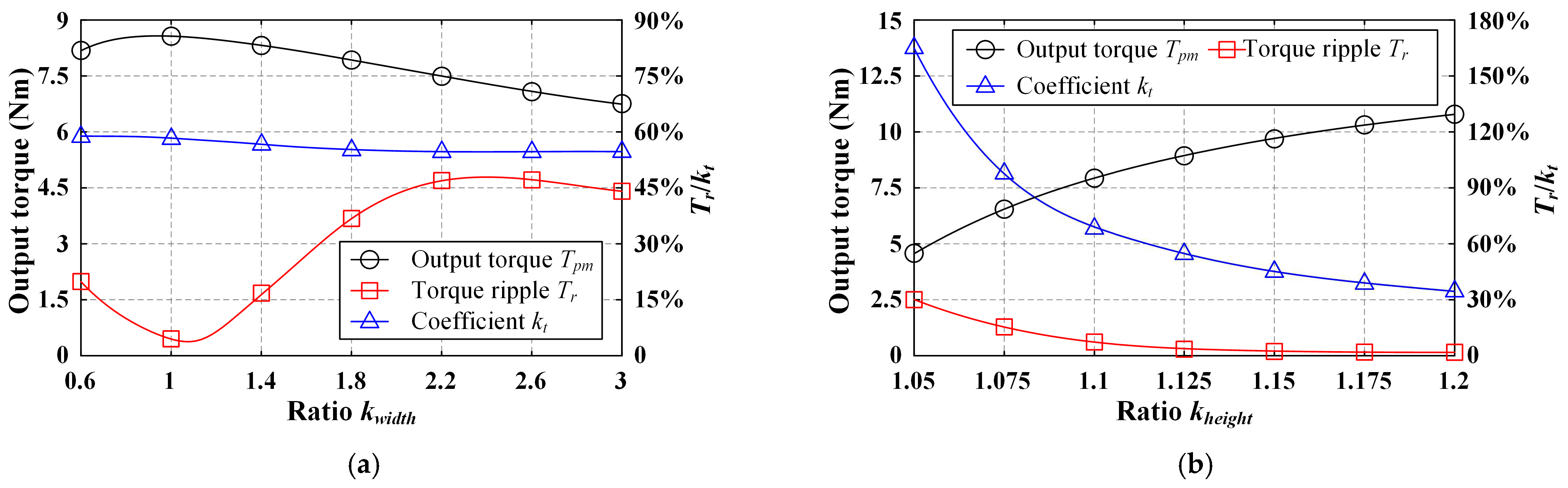
3.4.2. Rotor Parameters

As shown in Figure 10, the key rotor parameters should also be analyzed, such as the width of Type-A PM wpa and Type-B PM wpb, the distribution coefficient kdc of U-type PM, and the PM angle. First, Type-A PM refers to the central part in the U-type PM and Type-B PM refers to the rectangular PMs on both side of the U-type PM. Second, distribution coefficient kdc refers to the total length ratio of Type-A PM and Type-B PM. Then, distribution coefficient kdc can be expressed as
k dc = h pa 2 h pb × 100 %
where hpa and hpb refer to the heights of Type-A PM and Type-B PM. Third, the PM angle αp refers to the angle between Type-A PM and Type-B PM. The flux leakage is mainly determined by αp; thus, αp is also obviously a key dimension in the FTCPHE machine.
According to Figure 11, with the increasing wpa/wpb, it should be noted that the average output torque under only-PM state is slightly increased by around 6%. However, compared with the increment of PM usage, the increased average output torque is relatively small. Therefore, this FE-simulated result shows that PM usage does not adhere to “the larger the better” principle. When wpa/wpb is increased, the torque variation coefficient kt is almost unchanged, which is around 58%. In addition, the torque ripples can achieve to the lowest value when wpa = 3 mm/wpb = 2.5 mm.
The simulated result of the variations of the electromagnetic torques against the distribution coefficient kdc is illustrated in Figure 12. It should be noticed that coefficient kdc has no significant impact on torque ripple. Furthermore, the average output torque is improved by nearly 9~10% with the increasing kdc.
The variations of the electromagnetic torques against the PM arc are simulated and exhibited in Figure 13. Based on this figure, it can be seen that the average output torque increases at first and then decreases with PM arc αp. Furthermore, the torque ripples of Mode I and II reach the optimum values when αp = 120 deg. However, the maximum torque ripple of Mode III is obtained when αp = 120 deg.

4. Electromagnetic Performance

In this section, the electromagnetic performances of this proposed FTCPHE machine are FE-predicted, in which the correctness of the theoretical analysis mentioned above can be validated. According to the analysis results of the design refinement for the key structural parameters, the geometrical dimensions of the FTCPHE machine can be determined as exhibited in Table 2.

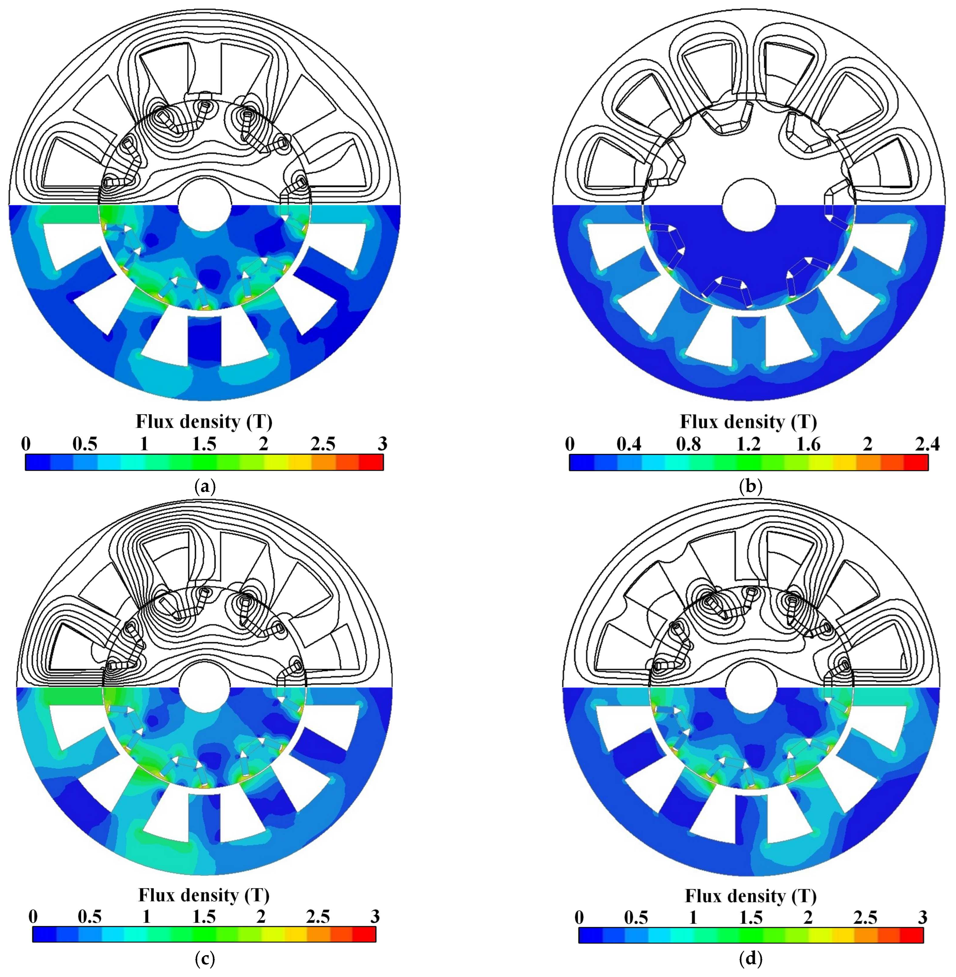
4.1. Flux Distribution

It should be noted that mesh discretization has a great impact on simulating accuracy of the FE method. Therefore, to achieve the accurate FE-predicted calculation, high mesh discretization is adopted for the FTCPHE machine, as shown in Figure 14.
The flux distribution generated by the PMs and DCs are simulated by the FE method. As exhibited in Figure 15a,b, it can be found that there are two fluxes generated by the PMs and DCs, respectively, which can achieve a unique harmonic field coupling effect in the air gap. In addition, due to the unique relation between these two magnetic fluxes, the risk of irreversible demagnetization in this FTCPHE machine can be eliminated effectively. The flux distributions of the FTCPHE machine under the flux-enhancing state and the flux-weakening state are shown in Figure 15c,d; thus, the analytical results mentioned in Section 2 can be verified.

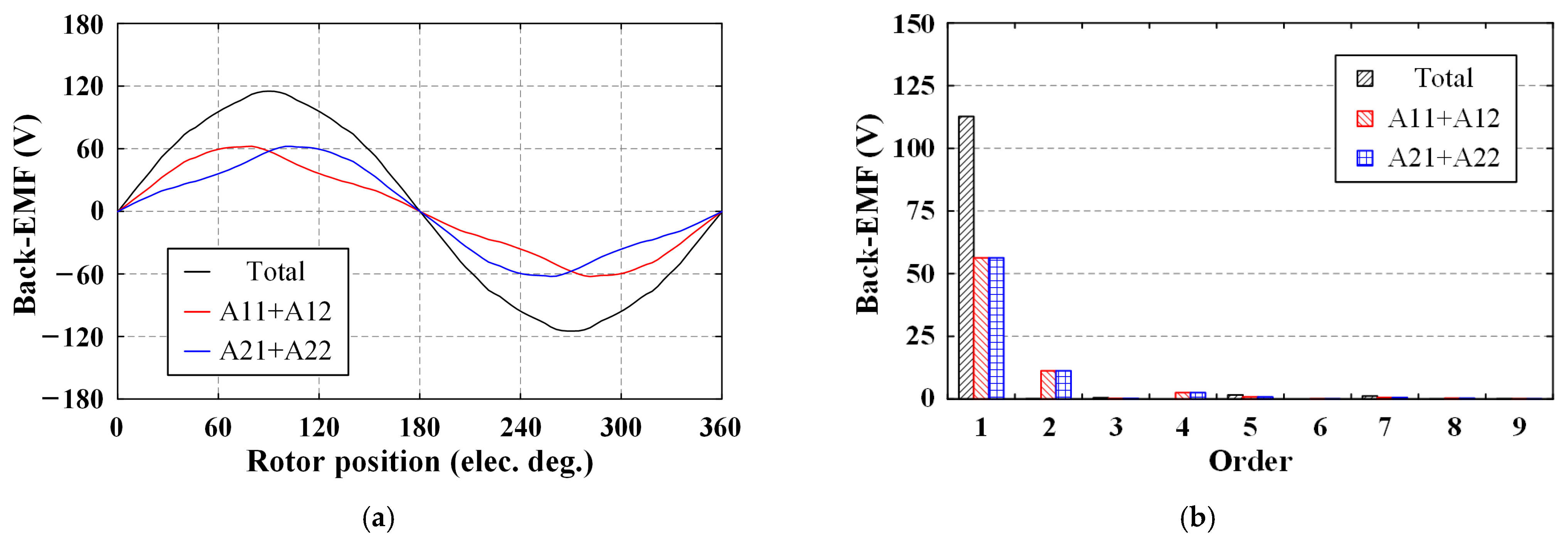
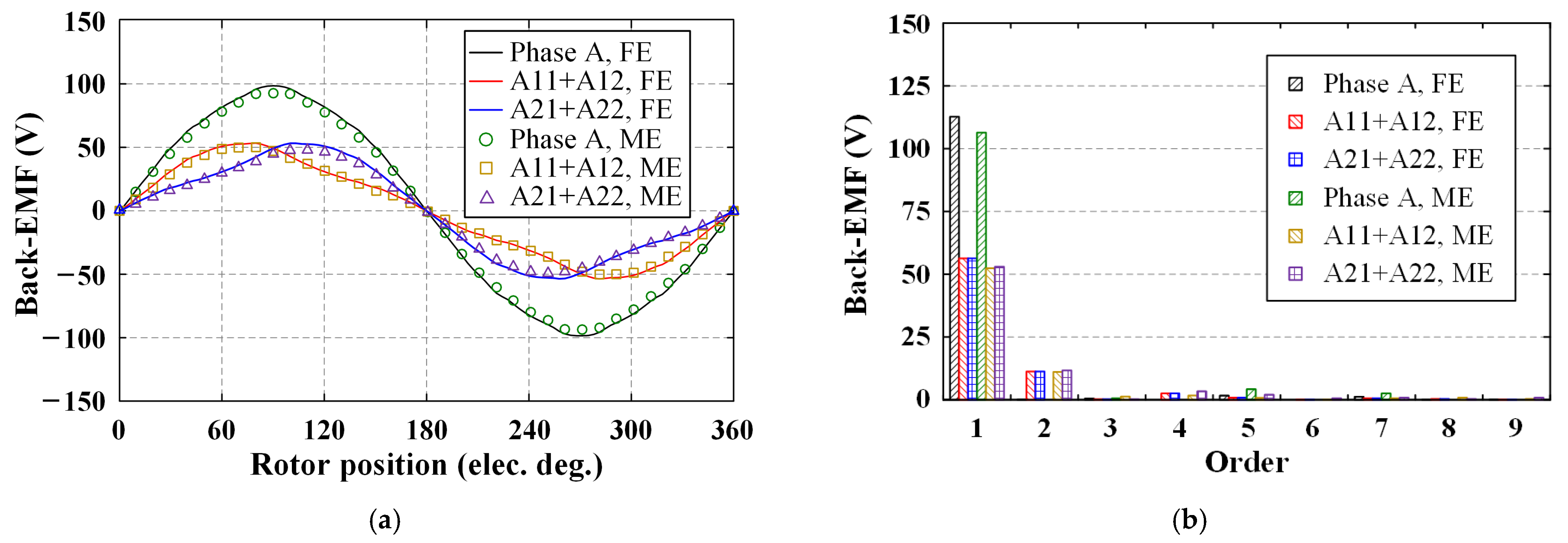
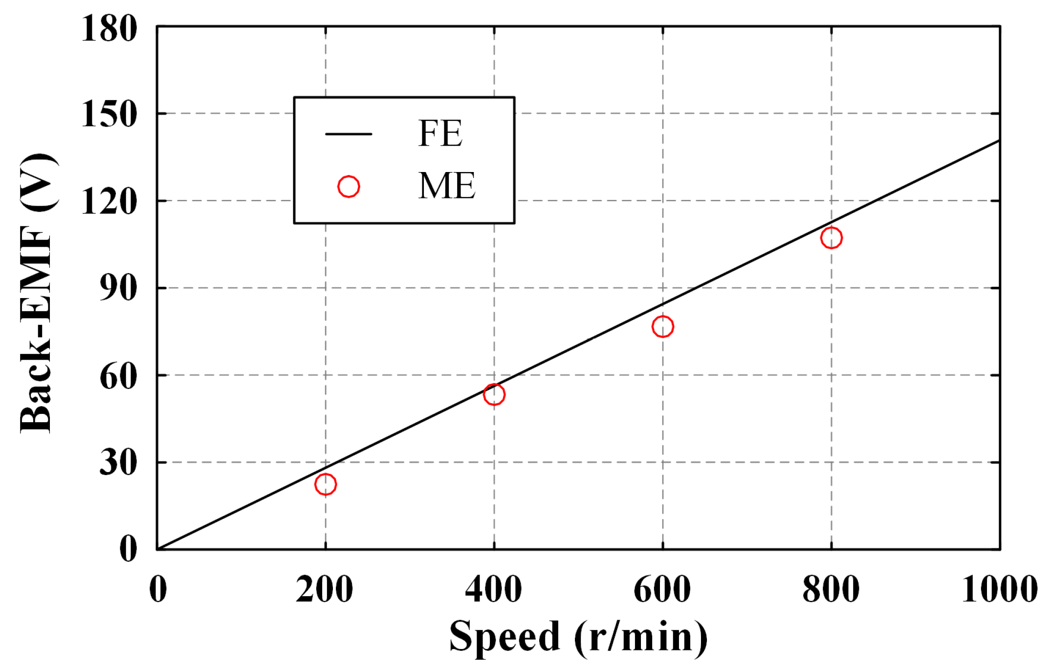
4.2. No-Load Back-EMF

The no-load back-EMF waveforms of Phase A are simulated by the FE method, as exhibited in Figure 16. It should be emphasized that the no-load back-EMF is composed of two types of coils: Coil A11 + A12 and Coil A21 + A22. It can be easily found that these two types of coils are asymmetrical. However, these two types of coils are complementary; thus, the even-order harmonic components in the total phase back-EMF are eliminated. Then, the total phase no-load back-EMF waveform at a rated speed is symmetrical, in which its THD value is around 2%.

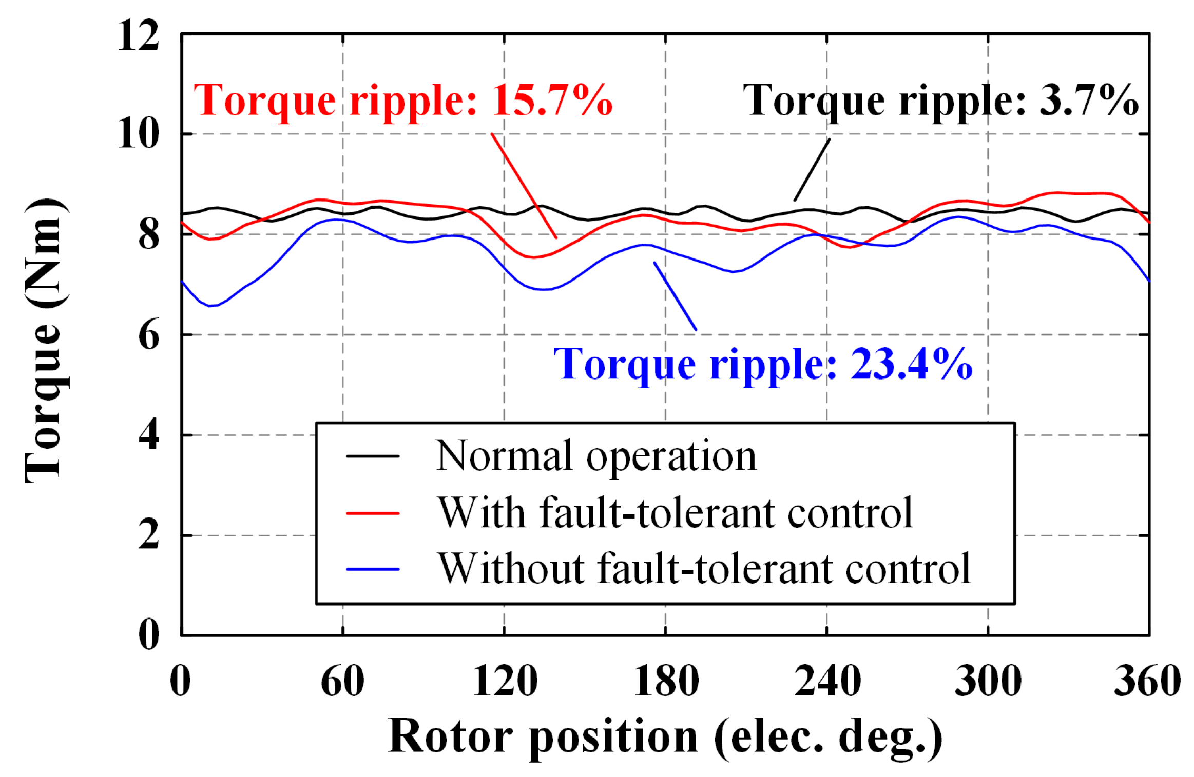
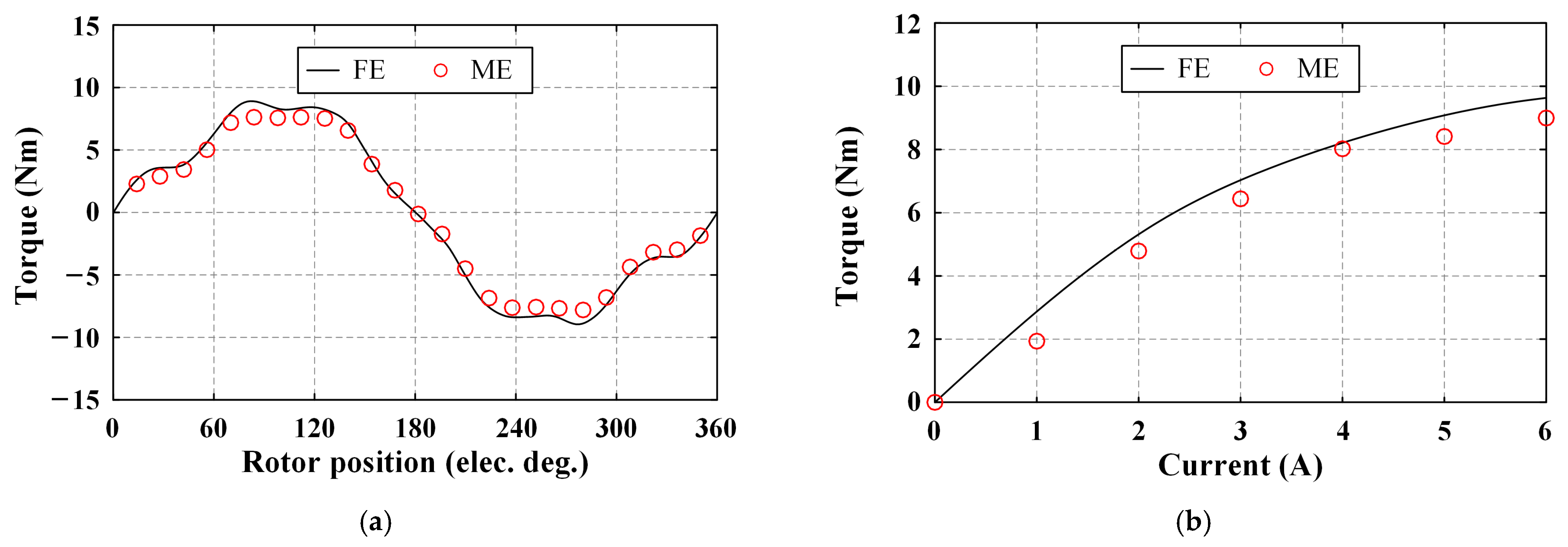
4.3. Electromagnetic Torque

For better application in EVs, the electromagnetic torques generated by the proposed FTCPHE machine are analyzed and discussed by the FE method, as shown in Figure 17 and Figure 18. First, the electromagnetic torques under only-PM/flux-enhancing/flux-weakening state are illustrated in Figure 17a. It can be seen that the torque ripple under flux-weakening state is larger than that of the flux-enhancing state. Furthermore, the main components in these torque waves are the 6th and 12th, as shown in Figure 17b. With the increasing DC, the torque ripple is decreased from 8.5% to 3.5%. In addition, the variation of the average output torques against DCs is exhibited in Figure 18. Based on these figures, it can be found that this unique harmonic field coupling effect in the FTCPHE machine is obvious.

4.4. Cogging Torque

According to the features of the fluxes in the proposed FTCPHE machine, it can be found that the main period βcog of the cogging torque [18,26] can be expressed as
β cog = 360 ° N cog N cog = LCM 2 p r o , Q s 2
where LCM(2pro, Qs/2) refers to the least common multiple (LCM) of 2pro and Qs/2. The cogging torque generated by the FTCPHE machine is simulated by the FE method, as shown in Figure 19. Based on the FE-predicted result, the period of the cogging torque of this proposed machine is equal to 8.6°; thus, good agreement can be achieved between Equation (12) and the FE method. In addition, it can be found that the peak-to-peak value of the cogging torque is around 850 mNm.

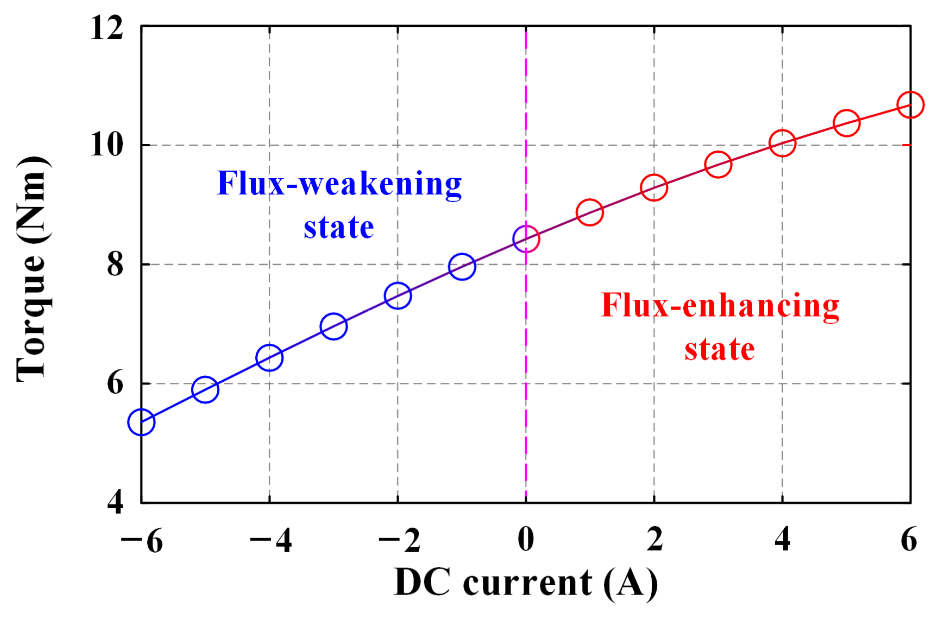
4.5. Fault-Tolerant Ability

The fault-tolerant ability of this proposed machine should also be analyzed beside the hybrid excited effect. As shown in Figure 20, when the one-phase open-circuit fault occurrs, the fault-tolerant control strategy is employed and compared to the output torque without fault-tolerant ability. Furthermore, under the one-phase open-circuit fault, the AC currents are set as
i A 1 = 0 ,   i A 2 = I am cos ω t + i 5 6 π i B 1 = I am cos ω t + i 5 6 π ,   i B 2 = I am cos ω t + i 5 6 π i C 1 = I am cos ω t i 5 6 π ,   i C 2 = I am cos ω t + i 5 6 π
where iA1, iA2 refer to the currents in Coils A11/A12 and A21/A22, iB1, iB2 refer to the currents in Coils B11/B12 and B21/B22, iC1, iC2 refer to the currents in Coils C11/C12 and C21/C22. Moreover, it should be emphasized that Coils A1 and A2 are the in the open-circuit fault; thus, iA1 is equal to zero. Compared to the output torque without fault-tolerant control, the output torque with fault-tolerant control is improved by 9.7%, and the torque ripple is decreased from 23.4% to 15.7%. In addition, it can be noted that the average output ability under the fault operation is similar with the normal operation. However, the torque ripple under the fault operation is increased. Therefore, with reasonable current distribution under the open-circuit fault, good fault-tolerant ability of the proposed FTCPHE machine can be proven.

5. Experimental Verification

To validate the analytical and FE-predicted results mentioned previously, a 12/14 FTCPHE prototype machine with the TW is manufactured and measured by two test platforms.

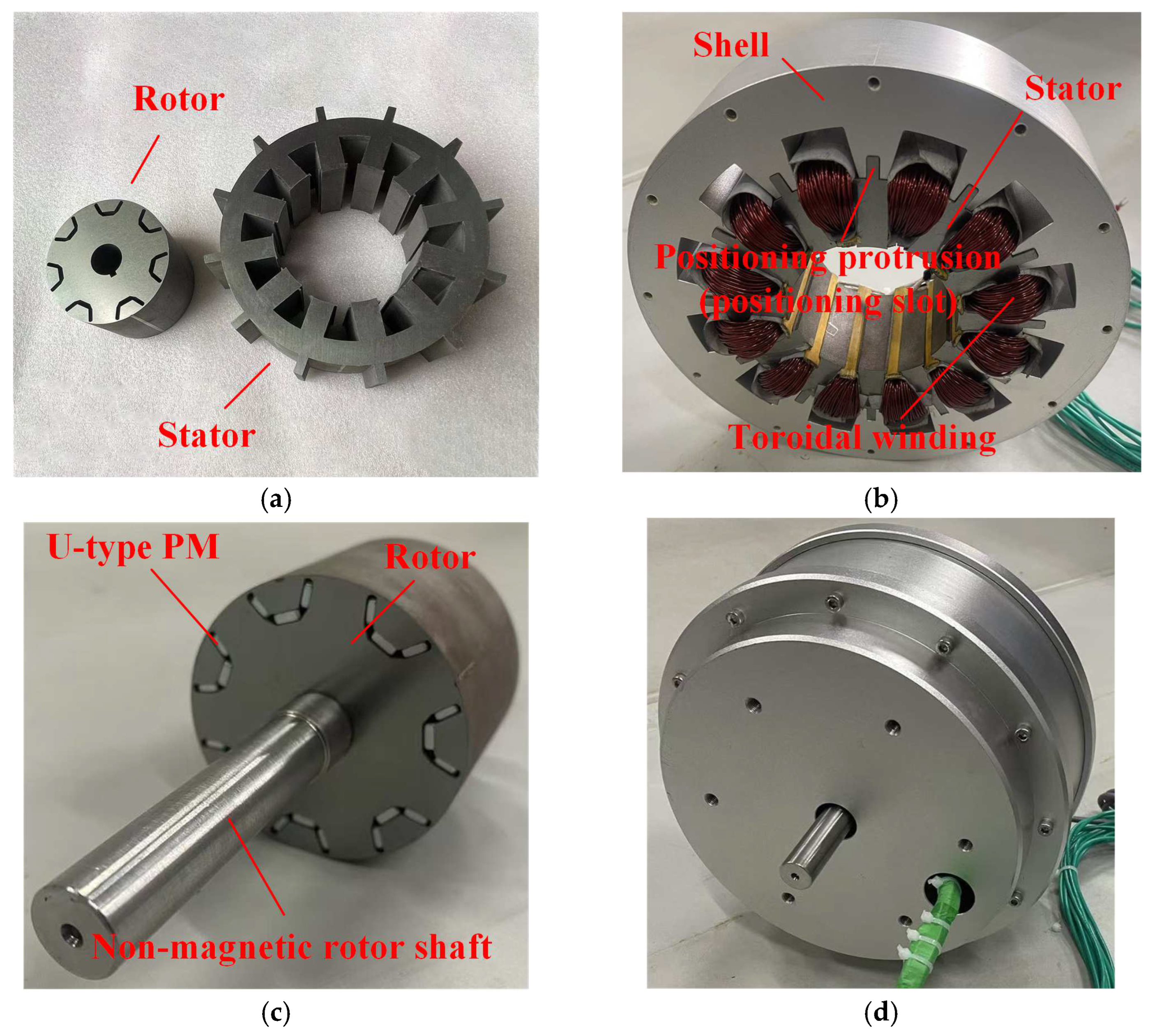
5.1. Prototype Machine and Test Platform

The main geometrical dimensions of this proposed prototype are listed in Table 2. The key components of this proposed prototype are shown in Figure 21, including the stator with the TW and the consequent-pole rotor with the U-type PM. The stator and its shell are exhibited in Figure 21b. It can be found that there are slots designed inside the shell to house the coils. There is a positioning slot between two adjacent slots. Similarly, the outside of the stator is equipped with positioning protrusions, which can be interlocked with positioning slots. Therefore, the stator can be fastened in the shell stably. The TW consists of 12 coils. Considering the processing difficulty, these coils are embedded in the stator at first. Then, the stator is coupled to the shell. The consequent-pole rotor and the rotor shaft are shown in Figure 21c. It should be noted that the U-type PMs are sealed in the rotor with the anaerobic adhesive for better robustness and tightness. The laminated rotor is supported by the non-magnetic rotor shaft, which is manufactured by the high-strength stainless steel.
Then, the test platforms for this proposed FTCPHE machine are established, which can be divided into two types. First, as shown in Figure 22a, the dynamic test platform, including the torque sensor, the servo motor and the prototype equipped with the encoder, is built for the measurement of back-EMFs. Second, as shown in Figure 22b, the static test platform, including the index table, the DC power supply, the digital gauge, and the balance beam, is built for the measurement of the cogging torque and the static torque. It should be emphasized that the cogging torque and the static torque can be measured by locking the rotor at different circumferential positions. In addition, the detailed measured method for the cogging torque and the static torque is divided into four steps as reported in [27,28].

5.2. Test Result

First, as shown in Figure 23a, the Phase A no-load back-EMFs of the proposed FTCPHE machine at rated rotating speed are measured and compared with the FE-predicted values considering the end effect (ME = measurement). It can be seen that the Phase A back-EMF is composed of two parts, which are clearly asymmetric. Moreover, it can be found that the measured waveforms (106.4 V) of the no-load back-EMFs are slightly lower than those of the simulated values (112.7 V), owing to the assembling error. As shown in Figure 23b, the THD values of both the simulated and the measured back-EMF are 2.1% and 3.8%, respectively. Good agreement can be achieved between them. Obviously, the error is caused by the manufacturing tolerance, and the experimental result is acceptable. The fundamental amplitudes of the back-EMFs of the FTCPHE machine with the TW at different rotating speed are tested, as shown in Figure 24. Obviously, good agreement can be obtained.
Second, the static torque of this proposed FTCPHE machine is measured in Figure 25. According to Figure 25a, it can be seen that good agreements between the simulated and the measured static torques are achieved. Compared with the simulated result considering the end effect, the peak-to-peak value (16.2 Nm) of the measured static torque is decreased by around 9.1%. The variation of the static torques against the q-axis armature current is shown in Figure 25b. The measured value is lower than that of the simulated value because of the processing error. In general, the test result is acceptable.
Third, the cogging torque can be measured by slowly rotating the three-claw chuck on the index table, as shown in Figure 22b. The measured cogging torque is exhibited in Figure 26. It can be found that the measured peak-to-peak value (1.1 Nm) of the cogging torque is nearly 1.2 times bigger than that of the simulated value (0.9 Nm). In addition, the measured value of the period of the cogging torque is close to 8.6°. Hence, good agreement between FE-predicted and measured cogging torques can be observed.

6. Conclusions

In this paper, a new FTCPHE machine which utilizes field modulation theory is proposed to achieve a unique electromagnetic coupling effect. First, the stator tooth is divided into the main tooth and the supplementary tooth, in which the main tooth is slightly larger in size than the supplementary tooth. Second, the U-type PM is employed in the consequent-pole rotor to improve torque density and decrease PM usage. Third, the TW is adopted in this machine to replace the complicated traditional winding structure. Fourth, based on the stator/rotor structure, two magnetic circuits can be constructed to achieve the hybrid excited effect. Fifth, the design method of this proposed machine is introduced. The torque equation and the power equation are determined. The key geometrical dimensions of the FTCPHE machine, including both the stator parameters and the rotor parameters, are discussed. Sixth, several electromagnetic properties, such as flux distributions, no-load back-EMFs, output torques, and cogging torques, are analyzed and simulated. Finally, a prototype of the FTCPHE machine is manufactured to validate the analytical and the FE-predicted results. Several key conclusions can be drawn:
  • The brushless hybrid excitation can be achieved by a new harmonic field coupling effect, in which reliability can be improved and the manufacture cost can be decreased. In addition, good flux regulation can also be achieved with this new electromagnetic coupling effect.
  • The U-type PM and the TW are located in the rotor and the stator, respectively. Therefore, good space utilization can be achieved in the FTCPHE machine.
  • With the consequent-pole structure, high torque density and low PM usage can be achieved in the proposed FTCPHE machine. In addition, torque ripple under different operating statuses can all be controlled within 10%, in which the lowest torque ripple can be decreased to 3.3%.
  • Both the AC and the DC can be combined in one set of integrated winding (TW). This winding structure can be significantly simplified, copper loss can be decreased, and fault-tolerant ability can be improved, which is helpful to reduce the manufacture cost and cycle.

Author Contributions

Conceptualization, methodology, software, G.Q. and Z.L.; validation, G.Q. and J.Y.; writing—original draft preparation, G.Q. and Z.L.; writing—review and editing, G.Q. and J.Y.; supervision, W.L.; funding acquisition, G.Q. and W.L.; resources, W.L. All authors have read and agreed to the published version of the manuscript.

Funding

This research was funded by University-Industry Collaborative Education Program of China, grant number 231107722072056.

Institutional Review Board Statement

Not applicable.

Informed Consent Statement

Not applicable.

Data Availability Statement

The original contributions presented in the study are included in the article, further inquiries can be directed to the corresponding author.

Conflicts of Interest

The authors declare no conflicts of interest.

Abbreviations

The following abbreviations are used in this manuscript:
FTCPHEFault-tolerant consequent-pole hybrid excited
PMPermanent magnet
EVElectric vehicle
THDTotal distortion harmonic
FWField winding
TWToroidal winding
AWArmature winding
FEFinite element
MEMeasurement
Back-EMFBack electromotive force
LCMLeast common multiple

References

  1. Tong, M.; Chen, Y.; Sun, L. An Approach to Motor Winding Optimization for HEFS Machine-Based Integrated On-Board Charging Systems. World Electr. Veh. J. 2024, 15, 502. [Google Scholar] [CrossRef]
  2. Zhao, W.; Liu, W.; Qu, G.; Jing, H.; Huang, J. Research on control and optimization of heavy-duty electromagnetic bearing of large-capacity energy storage flywheel. In Proceedings of the 2024 IEEE 10th International Power Electronics and Motion Control Conference (IPEMC2024-ECCE Asia), Chengdu, China, 17–20 May 2024; pp. 539–543. [Google Scholar]
  3. Souissi, A.; Abdennadher, I.; Masmoudi, A. Analytical Investigation of the Air Gap Flux Density of Surface-Mounted PMSMs With Irregular Pole Shapes. IEEE Trans. Ind. Electron. 2025, 72, 198–210. [Google Scholar] [CrossRef]
  4. Qu, G.; Fan, Y.; Wu, Z. Design and Analysis of a New Hybrid-Excited Permanent Magnet Machine With Unequal Teeth. IEEE Trans. Magn. 2019, 55, 8105805. [Google Scholar] [CrossRef]
  5. Michieletto, D.; Cinti, L.; Bianchi, N. Hybrid Excitation PM Synchronous Motors: Part I—Per Unit Analysis. IEEE Trans. Energy Convers. 2022, 37, 487–494. [Google Scholar] [CrossRef]
  6. Michieletto, D.; Cinti, L.; Bianchi, N. Hybrid Excitation PM Synchronous Motors: Part II—Finite Element Analysis. IEEE Trans. Energy Convers. 2022, 37, 495–504. [Google Scholar] [CrossRef]
  7. Cinti, L.; Michieletto, D.; Bianchi, N.; Bertoluzzo, M. A Comparison between Hybrid Excitation and Interior Permanent Magnet Motors. In Proceedings of the 2021 IEEE Workshop on Electrical Machines Design, Control and Diagnosis (WEMDCD), Modena, Italy, 8–9 April 2021. [Google Scholar]
  8. Zhang, Y.; Zhang, X.; Ren, J.; Meng, F.; Wu, J.; Pang, X.; Liu, W.; Kong, Z. Analysis of Electromagnetic Performance of Permanent Magnet and Convex Pole Electromagnetic Hybrid Excitation Generator. IEEE Trans. Energy Convers. 2024, 39, 1216–1229. [Google Scholar] [CrossRef]
  9. Cinti, L.; Bianchi, N.; Bertoluzzo, M. Performance and Short-Circuit Fault Analysis in Hybrid Excited and Interior PM Motors. IEEE Trans. Energy Convers. 2024, 39, 1412–1422. [Google Scholar] [CrossRef]
  10. Song, Z.; Liang, Y. Overview of High Overload Motors. IEEE Trans. Ind. Appl. 2024, 60, 8611–8626. [Google Scholar] [CrossRef]
  11. Tong, M.; Cheng, M.; Wang, S.; Hua, W. An On-Board Two-Stage Integrated Fast Battery Charger for EVs Based on a Five-Phase Hybrid-Excitation Flux-Switching Machine. IEEE Trans. Ind. Electron. 2021, 68, 1780–1790. [Google Scholar] [CrossRef]
  12. Zhang, G.; Hua, W.; Han, P. Quantitative Evaluation of the Topologies and Electromagnetic Performances of Dual-Three-Phase Flux-Switching Machines. IEEE Trans. Ind. Electron. 2018, 65, 9157–9167. [Google Scholar] [CrossRef]
  13. Wei, F.; Zhu, Z.Q.; Sun, X.; Yan, L.; Qi, J. Investigation of Asymmetric Consequent-Pole Hybrid Excited Flux Reversal Machines. IEEE Trans. Ind. Appl. 2022, 58, 3434–3446. [Google Scholar] [CrossRef]
  14. Hua, H.; Zhu, Z.Q. Comparative Study of Series and Parallel Hybrid Excited Machines. IEEE Trans. Energy Convers. 2020, 35, 1705–1714. [Google Scholar] [CrossRef]
  15. Hua, H.; Zhu, Z.Q. Novel Parallel Hybrid Excited Machines with Separate Stators. IEEE Trans. Energy Convers. 2016, 31, 1212–1220. [Google Scholar] [CrossRef]
  16. Wang, H.; Zhu, H.; Ding, S.; Dai, Y.; He, C.; Wang, X. A New Partitioned Stator Field Modulation Machine With H-Shape Permanent Magnet Excitation. IEEE Trans. Magn. 2022, 58, 8106906. [Google Scholar] [CrossRef]
  17. Zhang, L.; Fan, Y.; Lorenz, R.D.; Cui, R.; Li, C.; Cheng, M. Design and Analysis of a New Five-Phase Brushless Hybrid-Excitation Fault-Tolerant Motor for Electric Vehicles. IEEE Trans. Ind. Appl. 2017, 53, 3428–3437. [Google Scholar] [CrossRef]
  18. Qu, G.; Fan, Y. Design Procedure of a New Three-Segment Dual-Stator Permanent Magnet Machine for Electric Vehicles. IEEE Trans. Energy Convers. 2024, 39, 2676–2688. [Google Scholar] [CrossRef]
  19. Liu, C.; Chau, K.T.; Lin, F. A New Hybrid-Structure Machine with Multimode Fault-Tolerant Operation for Mars Rover. IEEE Trans. Magn. 2015, 51, 8207904. [Google Scholar] [CrossRef]
  20. Cai, S.; Zhu, Z.Q.; Mipo, J.C.; Personnaz, S. Investigation of Novel Doubly Salient Hybrid Excited Machine with Non-Overlapped Field Winding. IEEE Trans. Energy Convers. 2021, 36, 2261–2275. [Google Scholar] [CrossRef]
  21. Chen, Y.; Zhou, X.; Lu, M.; Xu, Y. Research on Air-Gap Field Modulation Effect of Torque Enhanced Hybrid Permanent Magnet Motor. IEEE Trans. Magn. 2024, 60, 8203106. [Google Scholar] [CrossRef]
  22. Wang, Q.; Niu, Q. A Novel Hybrid-Excited Dual-PM Machine with Bidirectional Flux Modulation. IEEE Trans. Energy Convers. 2017, 32, 424–435. [Google Scholar] [CrossRef]
  23. Li, J.; Wang, K. Analytical Determination of Optimal PM-Arc Ratio of Consequent-Pole Permanent Magnet Machines. IEEE ASME Trans. Mechatron. 2018, 23, 2168–2177. [Google Scholar] [CrossRef]
  24. Su, P.; Hua, W.; Hu, M.; Wu, Z.; Si, J.; Chen, Z.; Cheng, M. Analysis of Stator Slots and Rotor Pole Pairs Combinations of Rotor-Permanent Magnet Flux-Switching Machines. IEEE Trans. Ind. Electron. 2020, 67, 906–918. [Google Scholar] [CrossRef]
  25. Xiang, P.; Yan, L.; Guo, Y.; He, X.; Gerada, C.; Chen, I.M. A Concentrated-Flux-Type PM Machine With Irregular Magnets and Iron Poles. IEEE/ASME Trans. Mechatronics 2024, 29, 691–702. [Google Scholar]
  26. Rezaee-Alam, F. On-Load Cogging Torque Calculation in Surface-Mounted Permanent Magnet Motors Using Hybrid Analytical Model. IEEE Trans. Magn. 2024, 60, 8200110. [Google Scholar] [CrossRef]
  27. Li, J.; Wang, K.; Zhang, H. Flux-Focusing Permanent Magnet Machines with Modular Consequent-Pole Rotor. IEEE Trans. Ind. Electron. 2020, 67, 2274–3385. [Google Scholar] [CrossRef]
  28. Zhu, S.; Zhao, W.; Ji, J.; Liu, G.; Lee, C.H.T. Generation Mechanism and Suppression Measure of Electromagnetic Vibration in Permanent Magnet Synchronous Machine: A Review. IEEE Trans. Transp. Electrif. 2024, 10, 9513–9528. [Google Scholar] [CrossRef]
Figure 1. FTCPHE machine. (a) 3D topology; (b) Structure of conventional winding; (c) Structure of TW.
Wevj 16 00130 g001
Figure 2. Winding connections of FTCPHE machine. (a) For conventional winding; (b) For TW.
Wevj 16 00130 g002
Figure 3. Main magnetic circuits. (a) Circuit A; (b) Circuit B.
Wevj 16 00130 g003
Figure 4. Air-gap flux densities. (a) Waveforms; (b) Harmonics.
Wevj 16 00130 g004
Figure 5. Winding connections of inverter. (a) For conventional winding; (b) For TW.
Wevj 16 00130 g005
Figure 6. Stator parameters.
Wevj 16 00130 g006
Figure 7. Variations of electromagnetic torques against ratio kwidth/kheight. (a) kwidth; (b) kheight.
Wevj 16 00130 g007
Figure 8. Variations of electromagnetic torques against main tooth width wmt.
Wevj 16 00130 g008
Figure 9. Variations of electromagnetic torques against stator yoke thickness hsy.
Wevj 16 00130 g009
Figure 10. Rotor parameters.
Wevj 16 00130 g010
Figure 11. Variations of electromagnetic torques against ratio wpa/wpb. (a) wpa; (b) wpb.
Wevj 16 00130 g011
Figure 12. Variations of electromagnetic torques against distribution coefficient kdc.
Wevj 16 00130 g012
Figure 13. Variations of electromagnetic torques against PM arc αp.
Wevj 16 00130 g013
Figure 14. Mesh of geometry.
Wevj 16 00130 g014
Figure 15. Flux distributions. (a) PM excitation; (b) Electrical excitation; (c) Flux-enhancing (PM + DC) state; (d) Flux-weakening (PM-DC) state.
Wevj 16 00130 g015
Figure 16. No-load back-EMFs. (a) Waveforms; (b) Harmonic orders.
Wevj 16 00130 g016
Figure 17. Electromagnetic torques. (a) Waveforms; (b) Harmonic orders.
Wevj 16 00130 g017
Figure 18. Variation of output torques against DCs.
Wevj 16 00130 g018
Figure 19. Cogging torque.
Wevj 16 00130 g019
Figure 20. Fault-tolerant ability.
Wevj 16 00130 g020
Figure 21. FTCPHE machine with the TW. (a) Silicon steel sheet; (b) Stator; (c) Rotor; (d) Prototype.
Wevj 16 00130 g021
Figure 22. Test platforms. (a) For dynamic properties; (b) For static properties.
Wevj 16 00130 g022
Figure 23. Electromagnetic back-EMFs. (a) Waveforms; (b) Harmonic orders.
Wevj 16 00130 g023
Figure 24. Simulated and measured fundamental back-EMFs.
Wevj 16 00130 g024
Figure 25. Static torques. (a) Static torque against rotor position; (b) Static torque against q-axis current.
Wevj 16 00130 g025
Figure 26. Simulated and measured cogging torque.
Wevj 16 00130 g026
Table 1. Three operating modes.
TypeIIIIII
Current value4.5 A *5.625 A3.375 A
Current density5 A/mm26.25 A/mm23.75 A/mm2
* 4.5 A is the rated armature current.
Table 2. Geometrical dimensions.
ItemParameterItemParameter
Rated power (W)700Stator yoke thickness (mm), hsy12.5
Rated speed (r/min)800Stack length (mm)60
Rated torque (Nm)8.4Width of main tooth (mm), wmt14
Pole-pair number of rotor7Height of main tooth (mm), hmt21.1
Pole-pair number of TW1Width of supplementary tooth (mm), wst12.5
Pole-pair number of DC currents6Height of supplementary tooth (mm), hst19
Number of PMs7Width of Type-A PM (mm), wpa7.5
Number of iron cores7Height of Type-A PM (mm), hpa3
Number of Stator slots 12Width of Type-B PM (mm), wpb6.7
Number of main/supplementary teeth6/6Height of Type-B PM (mm), hpb2.5
Phase number3 × 2PM angle (°), αp120
Stator outside diameter (mm)147PM materialNdFeB
Stator inside diameter (mm)80PM remanence1.2 T
Rotor outside diameter (mm)79PM relative permeability1.05
Rotor inside diameter (mm)20Lamination type50 W 470
Air-gap length * (mm)0.5Conductor turns100
* Air-gap length refers to the length difference between the rotor outside diameter and the stator inside diameter determined by the main tooth instead of the supplementary tooth.
Disclaimer/Publisher’s Note: The statements, opinions and data contained in all publications are solely those of the individual author(s) and contributor(s) and not of MDPI and/or the editor(s). MDPI and/or the editor(s) disclaim responsibility for any injury to people or property resulting from any ideas, methods, instructions or products referred to in the content.

