Article

Design, Modeling, and Experimental Validation of a Hybrid Piezoelectric–Magnetoelectric Energy-Harvesting System for Vehicle Suspensions

1
University Mohammed VI Polytechnic (UM6P), Benguerir 43150, Morocco
2
Ecole Nationale Superieure de Chimie, Ibn Tofail University, Kenitra 14000, Morocco
3
Laboratory of Engineering Sciences for Energy, National School of Applied Sciences, Chouaib Doukkali University, El Jadida 24000, Morocco
*
Authors to whom correspondence should be addressed.
World Electr. Veh. J. 2025, 16(4), 237; https://doi.org/10.3390/wevj16040237
Submission received: 18 March 2025 / Revised: 30 March 2025 / Accepted: 15 April 2025 / Published: 18 April 2025

Abstract

:
The growing demand for sustainable and self-powered technologies in automotive applications has led to increased interest in energy harvesting from vehicle suspensions. Recovering mechanical energy from road-induced vibrations offers a viable solution for powering wireless sensors and autonomous electronic systems, reducing dependence on external power sources. This study presents the design, modeling, and experimental validation of a hybrid energy-harvesting system that integrates piezoelectric and magnetoelectric effects to efficiently convert mechanical vibrations into electrical energy. A model-based systems engineering (MBSE) approach was used to optimize the system architecture, ensuring high energy conversion efficiency, durability, and seamless integration into suspension systems. The theoretical modeling of both piezoelectric and magnetoelectric energy harvesting mechanisms was developed, providing analytical expressions for the harvested power as a function of system parameters. The designed system was then fabricated and tested under controlled mechanical excitations to validate the theoretical models. Experimental results demonstrate that the hybrid system achieves a maximum power output of 16 µW/cm2 from the piezoelectric effect and 3.5 µW/cm2 from the magnetoelectric effect. The strong correlation between theoretical predictions and experimental measurements confirms the feasibility of this hybrid approach for self-powered automotive applications.

1. Introduction

The increasing demand for sustainable and self-powered energy solutions has led to increasing interest in energy harvesting technologies, especially in applications where traditional power sources are impractical [1]. Several energy harvesting methods have been investigated for vehicle applications, including piezoelectric, electromagnetic, and triboelectric techniques [2,3]. Triboelectric nanogenerators (TENGs) are known for producing high voltages and being suitable for low-frequency excitations; however, they are highly sensitive to humidity, material wear, and surface degradation, all of which affect their durability and reliability under real-world conditions [4,5].
To overcome the individual drawbacks of these technologies, recent studies have explored hybrid energy harvesters that combine two or more transduction mechanisms to extend the operating frequency range, improve energy conversion efficiency, and ensure more robust operation across diverse road conditions [6,7]. These hybrid systems aim to create self-powered sensing platforms for intelligent vehicles, enhancing both energy autonomy and sensor network sustainability in connected automotive systems.
In the automotive sector, vehicle suspensions are constantly subjected to mechanical vibrations due to road conditions, braking, and acceleration. These vibrations, which are typically wasted as heat, represent a valuable energy source that, if effectively harnessed, could power wireless sensors, structural health monitoring systems, and autonomous electronic devices [8,9]. By converting these vibrations into electrical energy, vehicles could support self-powered sensor networks, reducing reliance on external energy sources and improving the overall energy efficiency.
Several methods have been explored for harvesting mechanical energy, with piezoelectric and electromagnetic mechanisms being among the most promising [10,11]. Piezoelectric materials, such as lead zirconate titanate (PZT) and polymer-based composites, generate an electrical charge when mechanically deformed, making them particularly effective at high frequencies [12,13]. However, their efficiency significantly drops at lower frequencies, which are more common in vehicle suspensions. Electromagnetic energy harvesting, on the other hand, relies on the relative movement of a magnet within a coil to generate electricity. This approach performs well at low frequencies, but its efficiency is highly dependent on the size of the components and precise mechanical alignment [14].
While both technologies have advantages, they also have significant limitations. Piezoelectric harvesters produce high voltage but low power outputs, making them less effective for sustained energy needs at low vibration frequencies. Electromagnetic harvesters are capable of generating higher power, but their effectiveness is limited by design constraints and the need for precise positioning and movement [15]. Most research so far has focused on using either piezoelectric or electromagnetic energy harvesting separately, an approach that limits the ability to adapt to the broad frequency range of real-world vehicle vibrations [16,17,18]. This underscores the need for a hybrid approach that can efficiently harvest energy across different operating conditions.
This study introduces a hybrid energy-harvesting system that integrates piezoelectric and magnetoelectric effects to efficiently convert mechanical vibrations from vehicle suspensions into electrical energy. By combining these two mechanisms, the system takes advantage of the high-frequency responsiveness of piezoelectric materials and the low-frequency efficiency of electromagnetic induction, ensuring higher energy conversion efficiency over a wider frequency range. The proposed system is designed to power autonomous sensors, wireless communication modules, and other embedded electronics, contributing to the development of self-sustaining smart vehicle technologies [19,20].
Systems engineering adopts a holistic, multidisciplinary approach to ensure the efficient design, implementation, operation, and decommissioning of systems. This methodology is governed by internationally recognized standards such as ISO 12588, IEEE 1220, and EIA-632 [21,22]. The process is organized into several key phases: requirement analysis, system design, implementation, verification, and validation. Each phase includes essential activities such as risk management, configuration management, and quality assurance. The main objective is to ensure that the system meets specified requirements, operates reliably and efficiently, and remains economically viable.
Model-based systems engineering (MBSE) represents a recent advance in this field [23], as it relies on models for the design and analysis of complex systems [24]. This systematic approach enables engineers to simulate system behavior, optimize performance, and identify potential problems before physical implementation. Unlike traditional trial-and-error approaches, MBSE allows for detailed simulations, helping engineers analyze mechanical, electrical, and material interactions within the system. This approach ensures that the final hybrid harvester is efficient, durable, and seamlessly integrated into vehicle suspensions, making it more viable for real-world applications [25].
This study presents the development of a hybrid energy-harvesting system that integrates piezoelectric and magnetoelectric effects to convert mechanical vibrations from vehicle suspensions into electrical energy. By combining these two mechanisms, the system enhances energy conversion efficiency and operates effectively across a broader frequency range. A model-based systems engineering (MBSE) approach is employed to guide the design process, ensuring structural compatibility, durability, and optimal performance. The study includes both theoretical modeling and experimental validation to assess the system’s effectiveness and provide insights into key design parameters. This hybrid approach offers a promising solution for self-powered sensor networks in smart vehicles, reducing dependence on external power sources and contributing to more sustainable automotive energy systems.

2. Materials and Methods

Figure 1 presents a summarized approach to the design and validation of the hybrid piezoelectric–magnetoelectric energy-harvesting system for vehicle suspensions. The study follows a structured process integrating model-based systems engineering (MBSE), architecture design, theoretical modeling, and experimental validation to ensure an optimized and functional system.
MBSE defines the system requirements and guides the architecture design to ensure compatibility with vehicle suspensions. Theoretical modeling establishes the expected energy output from both piezoelectric and magnetoelectric mechanisms, while experimental validation tests the system under controlled conditions to compare measured results with theoretical predictions.

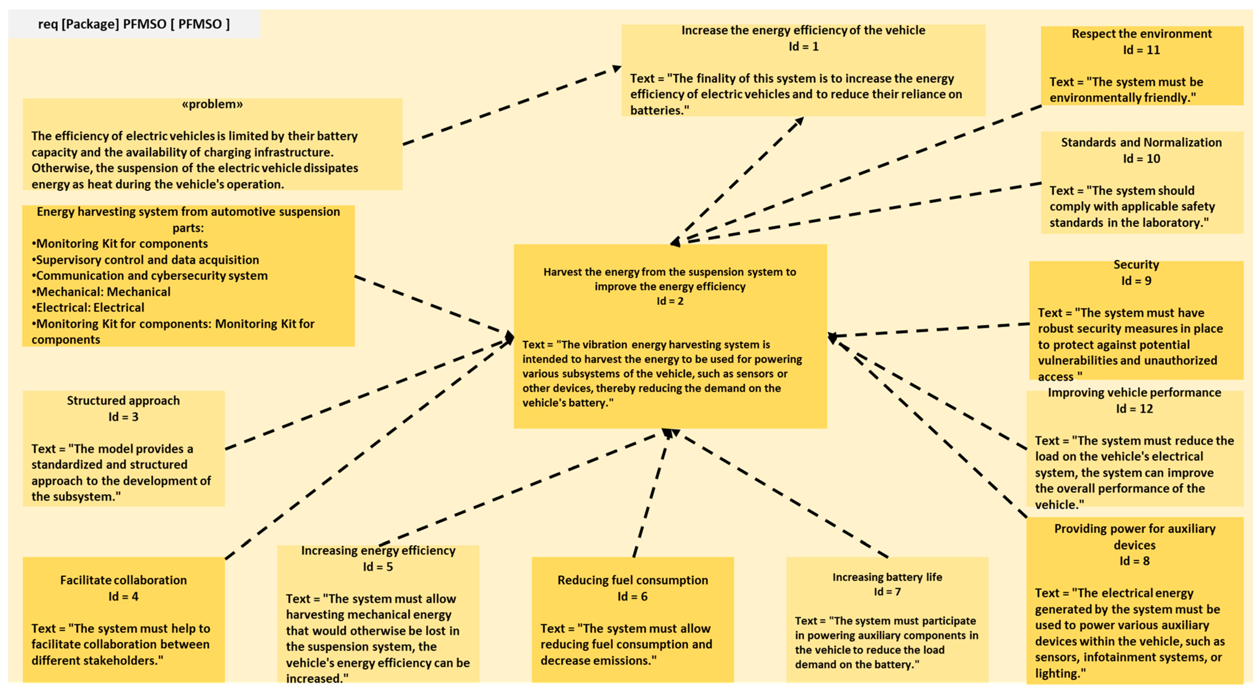
2.1. Model-Based Systems Engineering (MBSE)

2.1.1. Holistic Approach for Complex System Design

Model-based systems engineering (MBSE) is a comprehensive and multidisciplinary methodology designed to ensure the effective design, implementation, and lifecycle management of systems [26], as illustrated in Figure 2, which defines the scope of international standards like ISO 12588, IEEE 1220, and EIA-632. Derived from model-based design (MBD) in the 1990s, MBSE addresses the challenges of increasing system complexity by utilizing models to represent systems, their components, and their interactions [27]. Unlike traditional document-based methods, MBSE provides a structured, requirement-driven, and iterative approach that integrates key concepts such as system-level perspectives and dynamic model refinement throughout the design process.
At the core of MBSE’s functionality is its reliance on advanced modeling languages and tools, including SysML for graphical representations, Modelica for equation-based physical system modeling, Simulink for simulation of control and signal systems, and AADL for real-time architectural design. These tools enhance accuracy, streamline communication among stakeholders, and enable early detection of design flaws. Furthermore, MBSE supports diverse industries by facilitating the simulation of complex systems like aerospace vehicles, automotive suspensions, and power plants, ensuring design consistency and stakeholder alignment.
The advantages of MBSE are manifold: improved efficiency through reduced development time, enhanced accuracy by minimizing errors and inconsistencies, and stronger collaboration among engineering teams via shared modeling platforms. Despite its benefits, MBSE also presents challenges, such as steep learning curves for advanced tools and the need for ongoing research to enhance usability and scalability. By leveraging a model-based framework, MBSE offers a transformative solution for managing the complexities of modern system design while ensuring reliability, cost-effectiveness, and alignment with stakeholder objectives.

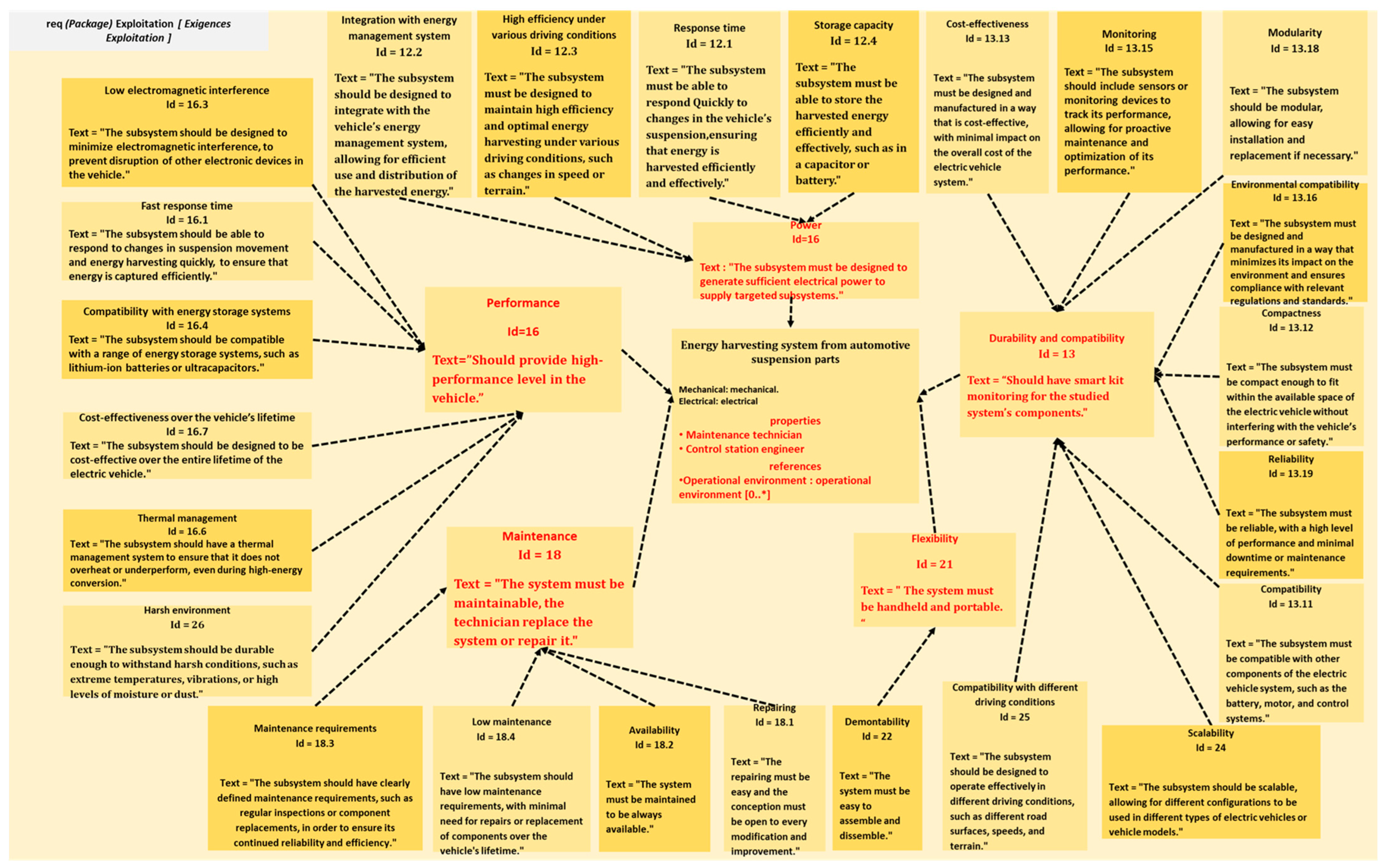
2.1.2. MBSE Design of the Vibration Energy-Harvesting System for Automotive Suspensions

This section presents the model-based systems engineering (MBSE) approach used in the design of a vibration energy-harvesting system from automotive suspensions, utilizing piezoelectric/magnetic materials. The primary issue being addressed is the wasted mechanical energy in the vehicle’s suspension system, which generates unutilized mechanical energy during movement. The goal is to capture this energy and convert it into electrical energy, which can then power various devices within the vehicle. Figure 3 illustrates the process of defining the problem, finality, mission, and objectives of the system. The finality of the system is to enhance the vehicle’s energy efficiency by converting wasted mechanical energy into usable electrical energy. The missions of this system include improving energy efficiency, reducing fuel consumption, increasing reliability, and providing power for auxiliary devices. The objectives focus on efficiently harvesting energy, converting it to electrical energy, and ensuring compatibility with the suspension system.
The MBSE methodology applied in this work involves multiple key stages. Initially, system requirements such as expected vibration frequency range, electrical output, and mechanical durability were defined. These constraints guided the material selection process—favoring flexible materials with proven electromechanical performance, such as porous EVA films. The application of MBSE involves using tools such as SysML for graphical modeling and Simulink for simulation and validation. SysML is used to define requirements, structure, and behavior through the use of use case diagrams, block definition diagrams, and parametric diagrams. The dynamic behavior of each subsystem (piezoelectric and magnetoelectric) was simulated in Simulink, allowing for the optimization of energy flow paths, voltage response, and power output under varying boundary and load conditions. Using Simulink and Catia V5, virtual models of the system architecture and material behavior under dynamic loading were developed and optimized. This simulation-driven design enabled the early evaluation of component interactions and ensured that both the piezoelectric and magnetoelectric modules met performance expectations before prototyping.
In the development of the vibration energy-harvesting system, the system requirements must be carefully defined to ensure the design’s effectiveness and reliability. As outlined in Figure 4, these requirements cover several key factors. Energy generation and conversion efficiency are crucial for the system to power intended devices and meet energy demands. Durability is vital for the system to withstand the automotive environment, including temperature fluctuations, vibrations, and shocks. The system must also be compact and lightweight to minimize its impact on vehicle performance and space. Furthermore, the cost-effectiveness of the system is a major consideration, as it must be affordable without compromising quality or performance. Safety and environmental impact are also essential aspects that need to be addressed throughout the design process.
By aligning these system requirements with the objectives and missions outlined earlier in Figure 3, the system is designed not only to improve the vehicle’s energy efficiency, but also to enhance the overall performance, safety, and sustainability. Figure 4 further clarifies the importance of integrating these requirements to ensure the system meets all necessary conditions for efficient operation, with particular emphasis on durability, compatibility, and cost-effectiveness under real-world conditions.

2.2. System Architecture of Subsystem Components

Figure 5 illustrates an innovative energy recovery system based on the vibrations of vehicle suspensions, composed of three complementary subparts. Figure 5a presents a 3D model of the system designed using Catia V5, highlighting the main components: a mechanical spring that absorbs vibrations, a coil that generates an electric current, and a permanent magnet that creates the magnetic field necessary for the induction phenomenon. Figure 5b shows the integration of this system within the suspension of a vehicle. The hybrid damper is positioned between the wheel and the chassis, combining the traditional function of shock absorption with an electromagnetic function that captures and converts vibrations generated by the vertical movements of the wheel on uneven surfaces. The coil is fixed to a compliant base, while the magnet is mounted on a spring-damped shaft that oscillates along the central axis of the coil. This configuration minimizes lateral displacement and maintains a consistent axial motion. The structure is enclosed in a protective casing that limits misalignment due to thermal expansion or high-frequency road shocks. The system mass remains below 200 g, which is negligible relative to suspension dynamics and does not adversely affect ride quality.
In Figure 5c, the resistances RL and RP represent the external electrical loads in the energy harvesting circuit. These components model the power dissipation across an electrical load. In practical applications, the harvested energy is typically stored in supercapacitors or rechargeable batteries via a rectifier and power management circuit to regulate and optimize energy transfer. The role of RL and RP in the diagram is to illustrate how energy is delivered to an external system.

2.3. Material Used for Energy Harvesting and the Experimental Setup for Measurement

2.3.1. Material Used for Piezoelectric Energy Harvesting

The polymer used in this work was a polymer designed essentially for the creation of microgenerators of energy harvested from ambient vibrations (Figure 6). The application of a low strain should be able to generate an electric voltage, which can supply an electrical device autonomously.
The matrix material used was random poly(ethylene-co-vinyl acetate). The copolymer (EVA, Greenflex® FC45F) was supplied by ENI Versalis Spa (Milan, Italy). The vinyl acetate content used was 14% by weight. Honeycomb EVA film was made using 2% Hydrocerol® ITP848 (Clariant, Muttenz, Switzerland) as a chemical blowing agent (CFA). Films made using this method have a thickness of approximately 160 to 310 µm (Figure 6). For more information, see the section titled “Films Refinement and Morphological Analysis” in our previous work.
The advantage of EVA 65% is that it is flexible and able to deform to the desired geometry. To study the feasibility of EVA 65% for road power harvesting applications, its electromechanical properties were evaluated and are shown in Table 1.
The selection of ethylene–vinyl acetate (EVA) in this study was based on its flexibility, mechanical durability, and ability to exhibit energy harvesting properties when processed into a porous structure. Previous research has extensively investigated the fabrication, characterization, and optimization of porous EVA films for energy harvesting applications. The use of EVA in piezoelectric energy harvesting has been further explored for applications in vibration-based power generation, where its mechanical adaptability provides advantages over traditional ceramic-based piezoelectric materials [11,28,29].
Given these findings, EVA was selected for its excellent mechanical flexibility, resilience under cyclic loading, and ease of integration into curved or non-planar surfaces such as vehicle suspensions. In contrast to brittle ceramic materials like PZT, EVA-based films can withstand repeated mechanical deformations without fracture. While PVDF exhibits good piezoelectric properties, its fabrication and poling processes are more complex and less suitable for porous structures. Additionally, porous EVA films have demonstrated pseudo-piezoelectric properties and have been successfully used in previous energy harvesting studies [29]. These attributes, combined with its cost-effectiveness and low density, make EVA an optimal choice for the hybrid system presented.

2.3.2. Experimental Setup for Measurement

In this study, electrical energy parameters have been measured for the active energy collection system. The configuration used to characterize the current and voltage collected by the flexible materials is illustrated schematically in Figure 7. Measurements were taken using a one-degree-of-freedom table. The material is held in place by two jaws, one of which is movable and attached to the table by one degree of freedom, while the other is stationary and connected to the load cell.
The NewPort table was controlled by a computational process, resulting in a wide range of deformations over a broad frequency band. At f m = 10 Hz, the film was stretched with a maximum transverse strain amplitude of 0.75%. The current and voltage produced by the piezoelectric materials were monitored using the Stanford SR 570 model (Stanford Research Systems Inc., Sunnyvale, CA, USA) and the Stanford SR 570 oscilloscope (Stanford Research Systems Inc., Sunnyvale, CA, USA).

3. Results and Discussion

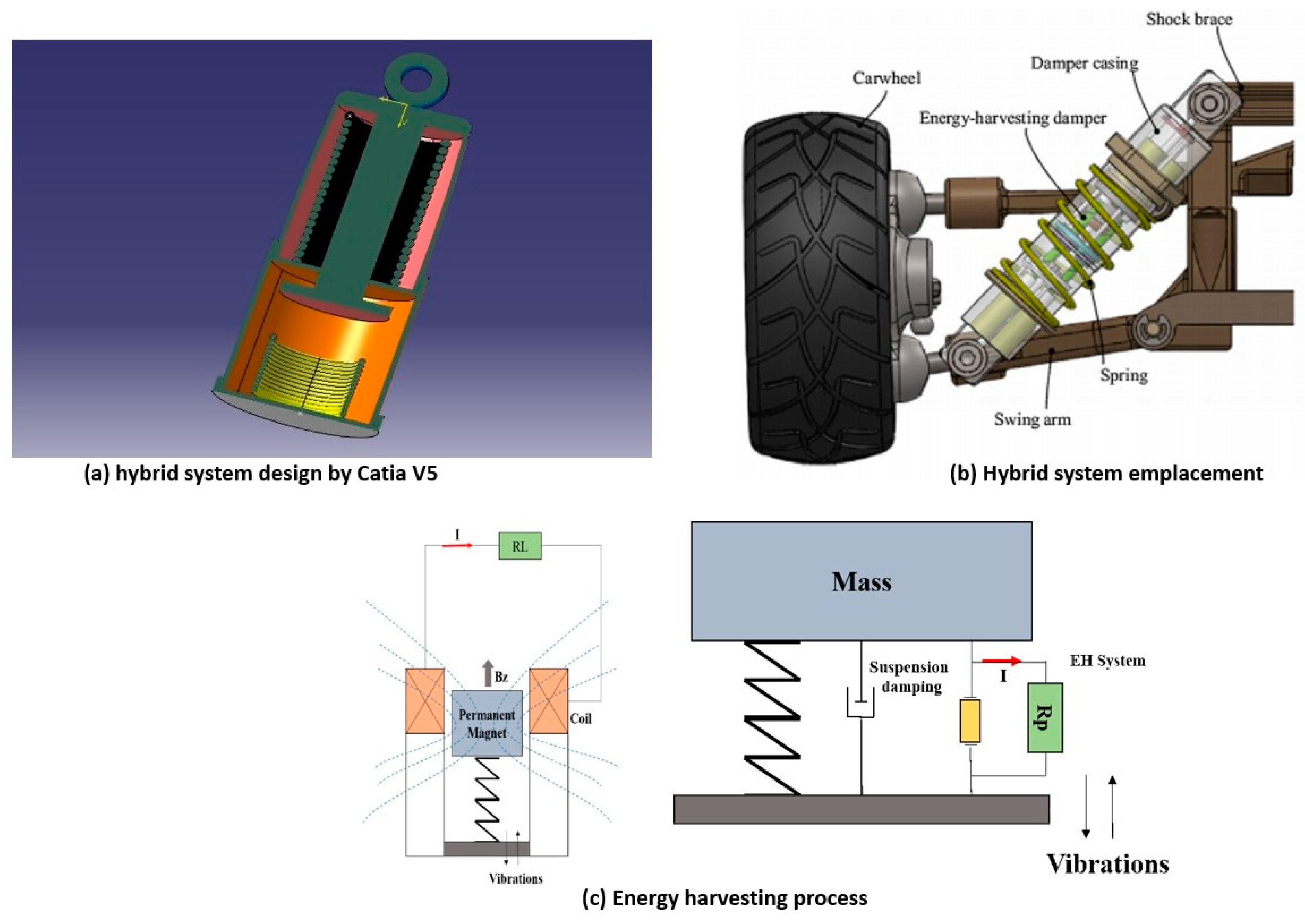
3.1. Theoretical Modeling of the Hybrid System

The analytical model of the hybrid harvester was developed under the following assumptions: linear elastic behavior of the structural materials, uniform strain distribution in the piezoelectric layer, linear magnetic flux variation, and constant damping characteristics. The system was modeled as a single degree-of-freedom (SDOF) mass–spring–damper under sinusoidal vertical excitation. The base was fixed, and the upper mass moved in response to vibrations. Electrical boundary conditions assumed resistive loading with no reactive elements. Environmental parameters such as temperature and humidity were held constant. These simplifications enabled tractable analytical solutions for an initial system evaluation and will be extended in future work using full multiphysics simulations.

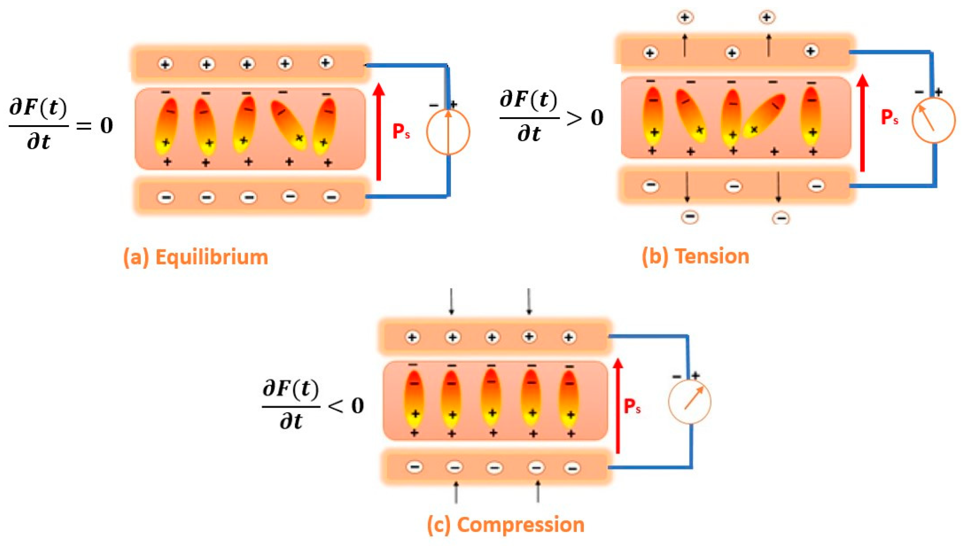
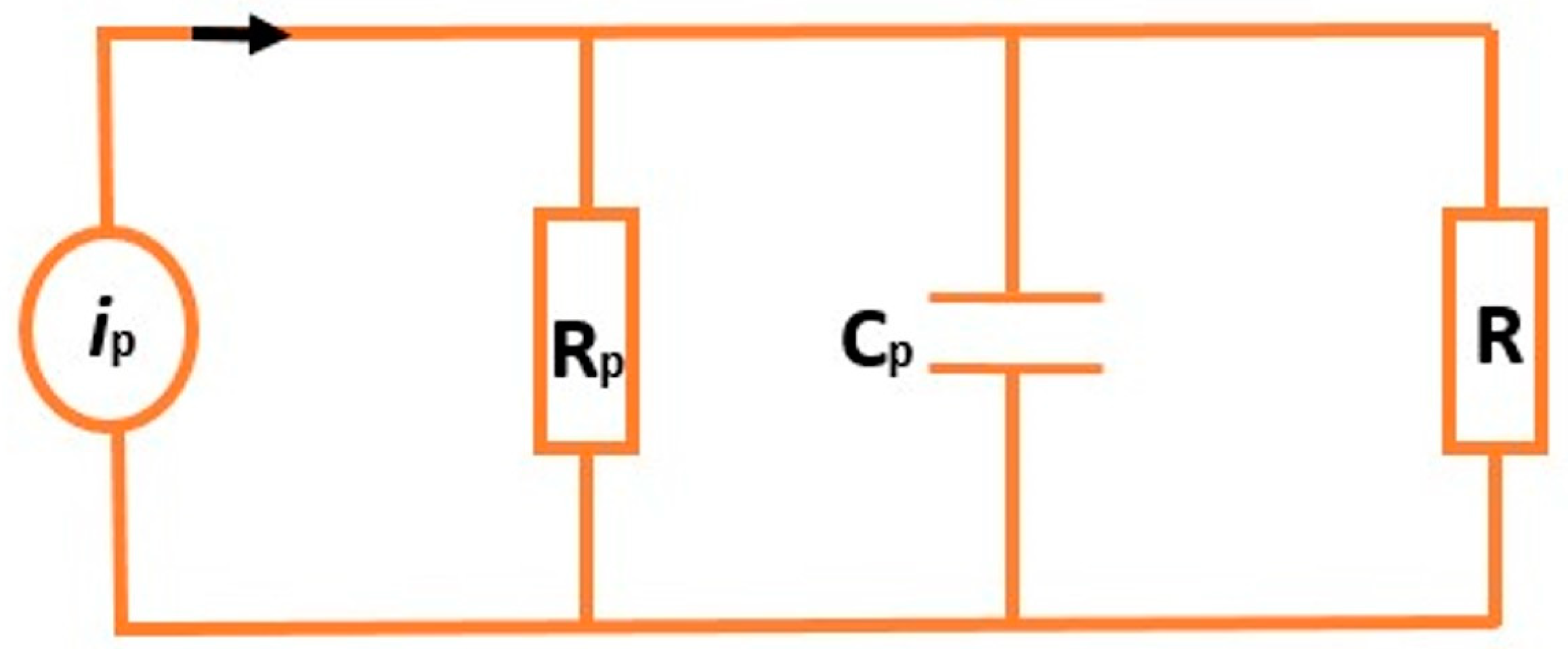
3.1.1. Theoretical Model of Power Harvested by the Piezoelectric System

Piezoelectric materials are divided into four main categories [30]: ceramics, single crystals, polymers, and composites. Of these, polymers are distinguished by their structure, composed of long chains of carbonaceous molecules made up of numerous repeating units called “monomers” [31]. These materials are far more flexible than ceramics or single crystals [32]. In certain applications, when specific properties cannot be obtained from a single type of material, these different groups can be combined to form composites [33].
A notable example is ethylene vinyl acetate (EVA), a polymer widely used for its flexible, tough, and transparent characteristics. In the piezoelectric field, EVA is often used as a matrix or support material, combined with piezoelectric materials such as PZT (lead zirconate titanate) or nanosheets of piezoelectric materials [34].
Piezoelectricity, the key property of these materials, enables them to generate an electrical charge when subjected to mechanical stress [30]. This phenomenon arises from the presence of naturally formed or artificially induced dipoles in their crystalline or molecular structure. Figure 8 illustrates the distribution of electrical charges in equilibrium and in disequilibrium, as well as the equivalent circuit for energy harvesting.
When a piezoelectric material is in mechanical equilibrium (Figure 8a), with no external force or stress applied, its internal electrical charges are symmetrically distributed [35]. However, under mechanical stress, such as compression, tension, or shear (Figure 8b,c), its crystalline structure deforms [36], causing an imbalance in charge distribution. This causes a relative shift in the centers of gravity of the positive and negative charges.
In this work, the force was applied along axis 1, perpendicular to the direction of polarization (axis 3), and the electrical charges generated were collected on the same surface (perpendicular to axis 3).
For a given applied force, the electrical energy dissipated in an electrical resistor connected to the piezoelectric element (Figure 9) can be calculated according to Equation (1), where Rp and Cp are the equivalent electrical resistance and equivalent capacitance of the piezoelectric material, respectively:
P = R · R p 2 · ( A · ω · d t · σ t ) 2 R p 2 + ( R · R p · C p ω ) 2
where
  • R p and C p   are the equivalent resistance and capacitance of the piezoelectric element;
  • d t   is the transverse piezoelectric coefficient;
  • σ t   represents applied stress;
  • A is the active surface area of the material;
  • ω is the angular excitation frequency.
Equation (1) includes the electromechanical properties of the piezoelectric material, the geometric dimensions, and the characteristics of the external circuit (resistance R). The angular frequency of the mechanical excitation ω is given by the product of 2π and the frequency f. The transverse piezoelectric constant, d t , measures the efficiency of the conversion of mechanical stress into electrical charges, F is the amplitude of the applied mechanical stress, e is the thickness of the piezoelectric material, and A is the electroded surface area of the material. The relative dielectric permittivity under constant mechanical stress is denoted by ε T , and the modulus of elasticity measured under constant electric field is denoted by s E .
For the 31-mode, the electrical power is as follows:
P = R · R p 2 · ( A · ω · d 31 · σ 31 ) 2 R p 2 + ( R · R p · C p ω ) 2
In Equation (2), the numerator corresponds to the power recovered in the electrical circuit, such power depending exclusively on the electrical charge and current produced by the material as a result of its mechanical excitation. The denominator is made up of two terms. The first describes the system’s behavior at low frequencies, where power is at a maximum, since there is no frequency-related attenuation. The second term reflects the dissipation or attenuation caused by the excitation frequency. This dissipation increases rapidly with frequency, leading to a reduction in recovered power. This phenomenon indicates a capacitive behavior of the piezoelectric material [37].
Optimizing energy harvesting, therefore, requires adapting the electrical load to obtain maximum energy harvesting, as achieved through the following differential Equation (3):
P R = 0
Optimum resistance is given by Equation (4). This equation shows that the optimum load is inversely proportional to the angular frequency of the mechanical vibrations collected, decreasing as this frequency increases.
R o p t = 1 ω · A e · ( ε 11 T d 31 2 S 11 E )
The expression for maximum power as a function of optimum load resistance is given in the frequency domain by the following equation (Equation (5)), in terms of the quality factor (Q), which measures the energy efficiency of a resonant material, while ( ξ ) represents the damping factor.
P o p t = 1 2 π · f · e · d 31 2 Q · ξ · ( ε 11 T d 31 2 S 11 E ) · A · σ 31 2
This model highlights that power output strongly depends on frequency and material properties. Low-frequency mechanical excitations, typical in vehicle suspensions, lead to lower power density, requiring structural optimizations to maximize output. Unlike traditional approaches, this work integrates high-frequency piezoelectric harvesting with low-frequency magnetoelectric harvesting to enhance energy conversion efficiency over a broad frequency range

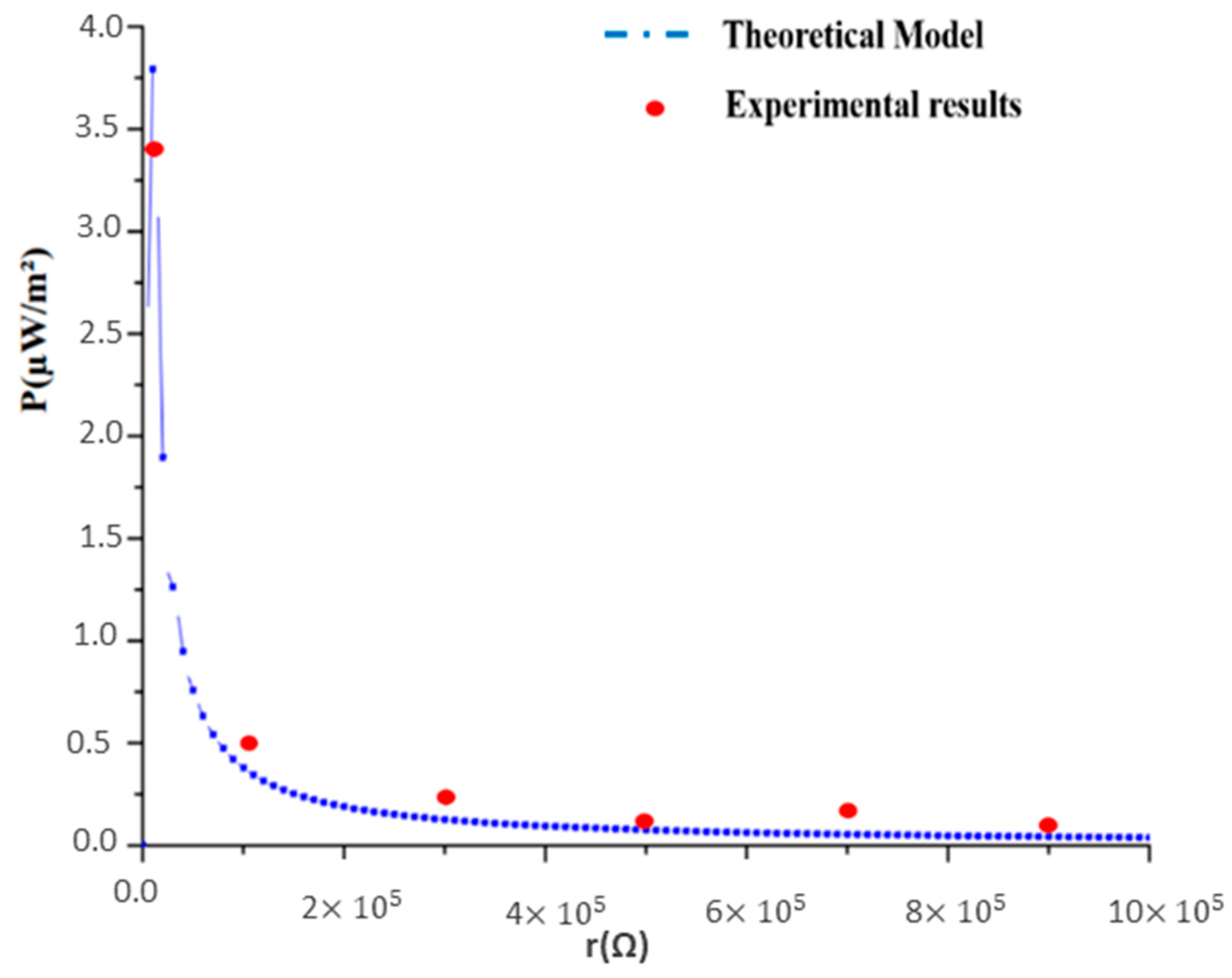
3.1.2. Theoretical Model of Power Harvested by the Magnetoelectric System

Moving a magnet close to a coil of wire (a conductor) reveals an electric current flowing through it [38]: this is the phenomenon of electromagnetic induction. As the magnet moves back and forth in front of the coil, the magnetic field in the space around the coil varies, generating an alternating current [39]. As the current varies in the coil, its own field also varies, as does its flux. According to Lenz’s law, a self-induced electromotive force (fem) arises, opposing the appearance of the current [40]. The coil, therefore, is equivalent to a Thévenin fem generator. In this case, the general expression for a current i(t) is as follows:
i t = L r i ( t ) t
In the frequency domain, the current is expressed as follows:
i j ω = L r + j · L ω
Using the fact that P = r· i 2 ( j ω ) , then P could be written as follows:
P = r · L 2 r 2 + ( L ω ) 2
where
  • L = μ 0 · N 2 . S l is the magnetic induction;
  • ω is the pulsation;
  • S is the surface of a spire;
  • l is the length of a spire.
P r = 0
The optimum power-maximizing load r is obtained through the following equation:
r = L · ω
The expression of maximum power as a function of optimum load resistance is provided in the frequency domain by the following equation (Equation (10)):
P o p t = L 2 ω
These equations indicate that magnetoelectric harvesters perform efficiently at lower frequencies, complementing the frequency-dependent limitations of piezoelectric devices. This hybrid system exploits this synergy to enhance energy harvesting efficiency.

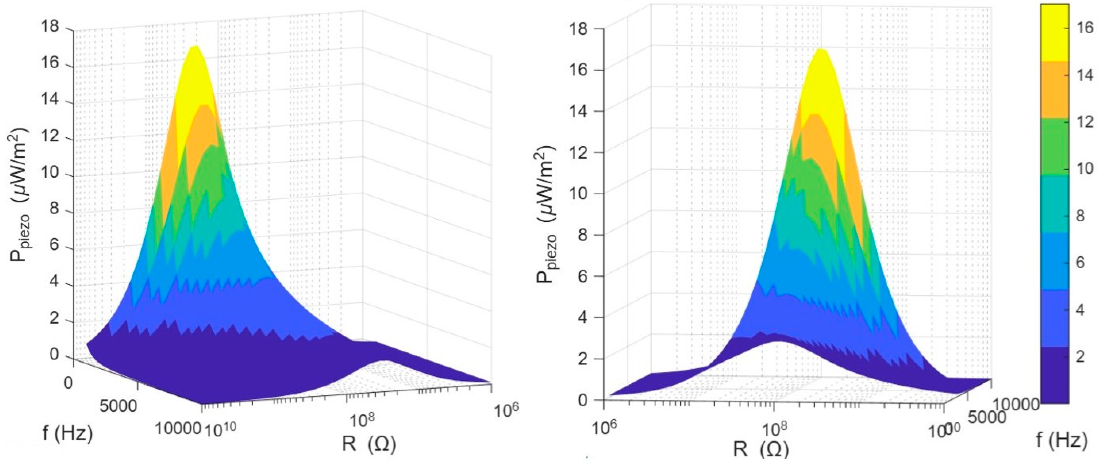
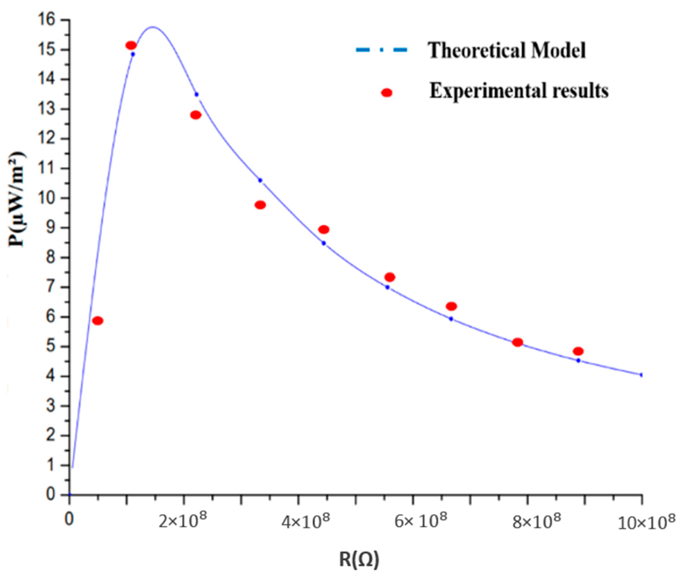
3.2. Piezoelectric Energy-Harvesting System Response

Figure 10 illustrates the piezoelectric power variation over area with resistance R and frequency. It shows that, for a given frequency, area power density increases with the electric charge until it reaches a maximum, after which the power decreases, even though the electric charge continues to decrease. This behavior is consistent with Equation (4), which shows that the electrical power is at its maximum when the charge R is equal to Ropt. Furthermore, this equation shows that the optimum charge is inversely proportional to the material’s natural frequency. Consequently, as the vibration frequency of the mechanical source increases, the optimum electrical load decreases, leading to an increase in the natural vibration frequency of the EVA.
At a frequency of 10 Hz, the piezoelectric power density generated by the EVA reaches a maximum value of 17 µW/m2 for an optimum load of 150 MΩ. This maximum value decreases to around 2 µW/m2 as the frequency increases to 10 kHz.
Figure 11 shows a comparison between experimental and analytical results for the electrical power per unit area generated by the EVA as a function of electrical load, for a frequency of 10 Hz. Excellent agreement is observed between the experimental values of the harvested power and those predicted by the analytical model. The experimental results show that the electrical power increases significantly with an increasing electrical load, reaching a maximum of 15.5 µW/m2 for an optimum load of 144 MΩ. Beyond this point, the power decreases, although the electrical load continues to increase. These observations validate the analytical modeling of the optimum electrical power generated by the piezoelectric effect, and clearly demonstrate the dependence of EVA-generated power on both electrical load and frequency. The results presented in this section are in agreement with those found in the literature [41,42].

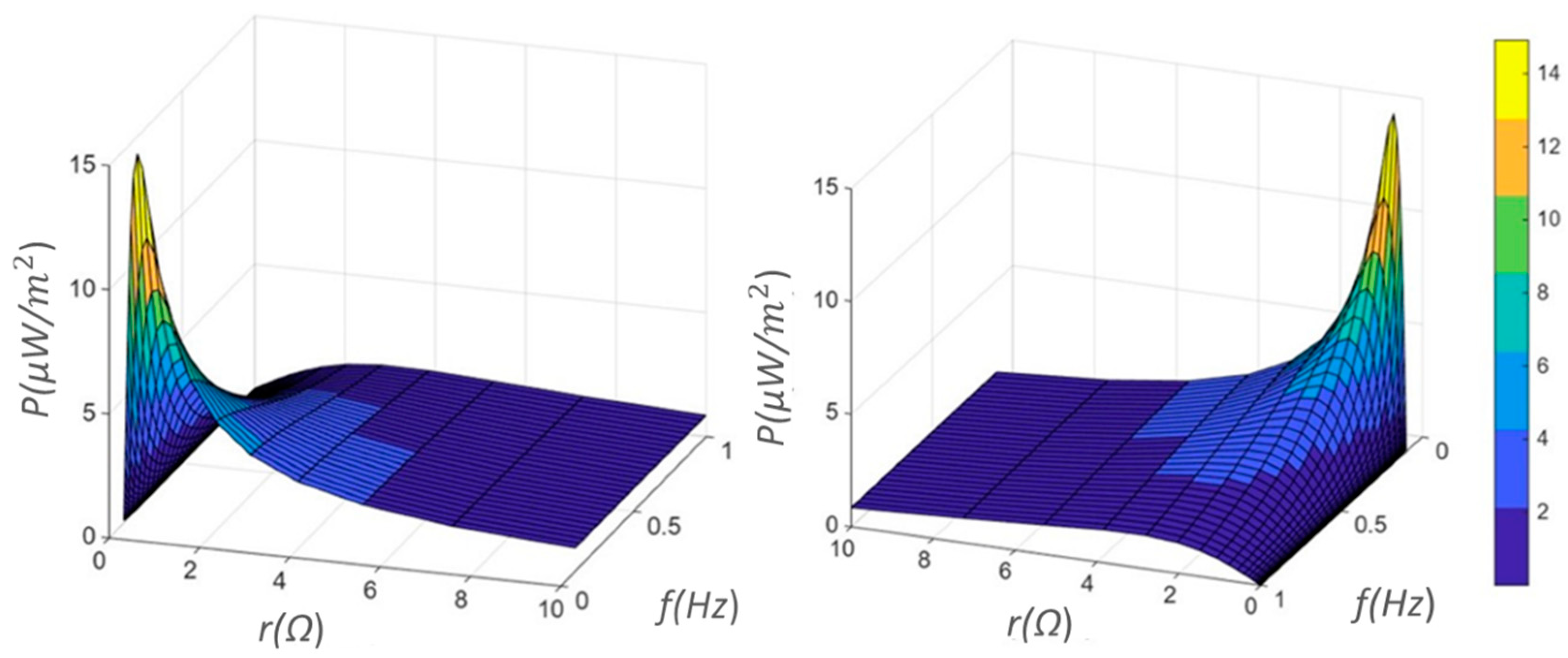
3.3. The Magnetoelectric Energy-Harvesting Response of the System

Figure 12 illustrates the evolution of magnetoelectric power as a function of resistive load and magnet oscillation frequency. According to this figure, for a given frequency, the power harvested by the magnetoelectric effect increases with the electrical load until it reaches a maximum, corresponding to the optimum load (r = L.ω), which is consistent with Equation (8). Thereafter, this power decreases as the oscillation frequency of the permanent magnet decreases, highlighting the influence of frequency on magnetoelectric power. At a frequency of 0.1 Hz, the optimum inductance is L = 2.4 H, the optimum load is 1.5 Ω, and the maximum power flux density reaches 15 µW/cm2.
Figure 13 shows the comparison between analytical and experimental results for an oscillation frequency of 1 Hz. According to these results, the power recovered by the electromagnetic effect per unit area increases with the resistive load, reaching a maximum of 3.5 µW/cm2 for an optimum load of 20 Ω. After this peak, the recovered power decreases, although the load continues to increase, which is in line with the predictions of the analytical model.
The hybrid energy-harvesting system of this study utilizes a piezoelectric component that was tested under controlled vibration conditions. The system achieved a peak power output of 16 µW/cm2 at a frequency of 10 Hz. This performance is comparable to that obtained following recent advancements in piezoelectric energy harvesters. For instance, a study reported a flexible amorphous calcium copper titanate (CCTO) thin-film harvester generating significant power under bending vibrations [15]. Another research study demonstrated a stretchable piezoelectric energy harvester (SPEH) using a kirigami-structured polyvinylidene fluoride (PVDF) film, which improved energy output [43].
The magnetoelectric component of our system was evaluated at low-frequency vibrations ranging from 0.1 to 1 Hz, achieving a maximum power density of 3.5 µW/cm2. This aligns with findings from studies on magnetoelectric composites. For example, research on magnetoelectric (ME) devices has demonstrated enhanced energy harvesting properties under specific configurations [44]. Additionally, investigations into self-biased magnetoelectric composites have shown promising results for energy harvesting applications [45,46].

3.4. Comparative Analysis of Energy-Harvesting Systems

Hybrid energy-harvesting systems have been explored in previous studies, primarily focusing on piezoelectric, electromagnetic, and magnetoelectric mechanisms. These approaches demonstrate significant potential for converting vibrational energy into electrical power, particularly in automotive applications. However, existing designs often face limitations in frequency adaptability, power density, and integration feasibility. This work presents a hybrid system that combines piezoelectric and magnetoelectric effects to achieve a broader operational frequency range and enhanced energy conversion efficiency.
Unlike conventional hybrid systems that combine piezoelectric and electromagnetic components, our approach strategically integrates piezoelectric and magnetoelectric mechanisms to achieve a complementary performance across a wider frequency spectrum. The piezoelectric element (EVA-based) is optimized for high-frequency excitations (≥10 Hz), while the magnetoelectric subsystem performs efficiently at low-frequency vibrations (≤1 Hz). Moreover, the MBSE framework ensures the co-design and integration of these two mechanisms within the physical constraints of vehicle suspension systems, thereby addressing both frequency range adaptability and mechanical feasibility.
Several studies have investigated piezoelectric energy harvesters based on lead zirconate titanate (PZT) ceramics, which exhibit high energy conversion efficiency at higher frequencies. These materials have been widely used for vibration-based energy harvesting due to their high piezoelectric coefficients. However, their performance declines at lower frequencies, which are more common in vehicle suspensions. Other works have explored electromagnetic energy harvesters, where power generation relies on the relative movement between a coil and a magnet. These systems are effective at low frequencies but require precise mechanical alignment to maximize energy conversion. Table 2 presents a comparative analysis of our hybrid system and relevant studies in the field of vibration-based energy harvesting.
The comparison with existing studies highlights the operational frequency range and energy conversion efficiency of different energy-harvesting approaches. While piezoelectric and magnetoelectric harvesters show an effective performance within specific frequency ranges, hybrid systems, including the one developed in this study, extend the range by combining both mechanisms.
Our results align with previous findings, confirming the influence of material selection and system design on harvested power. The integration of both effects in a single system allows for a more adaptable energy-harvesting approach, particularly in variable-frequency environments such as vehicle suspensions. Further optimization in energy storage and system integration could enhance the overall performance and application potential.
The proposed hybrid system integrates both piezoelectric and magnetoelectric mechanisms to extend the operational bandwidth of the harvester. The piezoelectric component, EVA, is optimized to generate power efficiently at high frequencies, while the magnetoelectric subsystem captures energy from low-frequency vibrations. This dual-mode approach enables continuous and more stable power output across a broad range of mechanical excitations. Experimental validation confirms that the system achieves a peak power density of 16 µW/cm2 from the piezoelectric component and 3.5 µW/cm2 from the magnetoelectric component. These values indicate a higher energy conversion efficiency compared to many previously reported single-mode harvesters operating under similar conditions.
Typical low-power automotive wireless sensors, such as tire pressure monitoring systems (TPMS), typically consume 10–50 µW in burst mode. Our hybrid system, producing 16 µW/cm2 (piezoelectric) and 3.5 µW/cm2 (magnetoelectric), can meet these needs when coupled with storage elements. For example, with an effective surface area of 3–5 cm2 and a 10% duty cycle, sensor power requirements can be met reliably. This supports its feasibility for self-powered sensor networks in modern vehicles.
The integration of lead-free materials in this work offers additional advantages in terms of durability and thermal stability. These materials retain stable piezoelectric properties under temperature variations, an attribute that is important for automotive applications. Moreover, the use of an optimized magnetoelectric configuration enhances power output under low-frequency conditions, ensuring effective energy harvesting from road-induced vibrations. Compared to previous research on hybrid systems, this work considers both material optimization and system integration to achieve a practical and scalable design.

4. Conclusions

Hybrid energy-harvesting systems offer a promising solution for enabling the development of self-powered and energy-efficient automotive technologies. This study addresses the critical need for broadband, durable harvesters capable of operating under the dynamic conditions of vehicle suspension systems. The work is particularly relevant in the context of electrification, embedded sensing, and the development of smart vehicle platforms under Industry 4.0. To achieve this, a model-based systems engineering (MBSE) approach was employed to define and optimize the hybrid system architecture. MBSE supported the design process through functional modeling, material selection, and system integration, using SysML and Simulink tools for simulation and validation, respectively, prior to fabrication.
This study developed and tested a hybrid energy-harvesting system that integrates piezoelectric and magnetoelectric effects to convert mechanical vibrations from vehicle suspensions into electrical energy. Experimental validation showed that the system generates 16 µW/cm2 from the piezoelectric component and 3.5 µW/cm2 from the magnetoelectric component, covering a broad frequency range, from 0.1 Hz to 10 Hz. These results closely align with theoretical predictions, confirming the feasibility and efficiency of the hybrid approach. The combination of piezoelectric and magnetoelectric mechanisms enhances energy conversion by addressing the limitations of single-mode energy harvesters, allowing for a stable performance across different vibration frequencies. A comparative analysis with existing studies highlights the improved adaptability and energy output of this system. Additionally, the use of model-based systems engineering (MBSE) facilitated optimized design, better integration, and durability, making the system more compatible with real-world applications.
Real-world deployment of hybrid energy harvesters in automotive environments requires resilience to mechanical fatigue, temperature fluctuations, and potential exposure to moisture or dust. The system has been structurally designed using mechanically flexible materials and protective enclosures to limit degradation under stress. Future research will focus on long-term stability, scalability, and integration into smart vehicle systems. These findings contribute to the advancement of sustainable, self-powered energy solutions, supporting the development of more efficient and autonomous technologies in the automotive industry.

Author Contributions

Conceptualization, H.M., A.E., M.R., E.S., M.D., H.E.H. and C.E.; methodology, H.M., A.E., M.R., E.S., M.D., H.E.H. and C.E.; validation, H.M., A.E., M.R., E.S., M.D., H.E.H. and C.E.; formal analysis, H.M., A.E., M.R., E.S., M.D., H.E.H. and C.E.; investigation, H.M., A.E., M.R., E.S., M.D., H.E.H. and C.E.; resources, H.M., A.E., M.R., E.S., M.D., H.E.H. and C.E.; data curation, H.M., A.E., M.R., E.S., M.D., H.E.H. and C.E.; writing—original draft preparation, H.M., A.E., M.R., E.S., M.D., H.E.H. and C.E.; writing—review and editing, H.M., A.E., M.R., E.S., M.D., H.E.H. and C.E.; visualization, H.M., A.E., M.R., E.S., M.D., H.E.H. and C.E.; supervision, H.M., A.E., M.R., E.S., M.D., H.E.H. and C.E.; project administration, H.M., A.E., M.R., E.S., M.D., H.E.H. and C.E.; funding acquisition, H.M., A.E., M.R., E.S., M.D., H.E.H. and C.E. All authors have read and agreed to the published version of the manuscript.

Funding

This research received no external funding.

Data Availability Statement

The original contributions presented in this study are included in the article. Further inquiries can be directed to the corresponding author.

Conflicts of Interest

The authors declare no conflict of interest.

References

  1. Remaidi, M.; Derraz, M.; Ennawaoui, A.; El Hmamsy, Y.; Mastouri, H.; Ennawaoui, C.; Hajjaji, A. Innovative Au-tonomous Lead-Free Hybrid Piezo-Pyroelectric Sensor for Real-Time Wear Assessment of Disc Brake Pads. Results Eng. 2025, 26, 104617. [Google Scholar] [CrossRef]
  2. De Neef, A.; Samuel, C.; Stoclet, G.; Rguiti, M.; Courtois, C.; Dubois, P.; Soulestin, J.; Raquez, J.M. Processing of PVDF-based electroactive/ferroelectric films: Importance of PMMA and cooling rate from the melt state on the crystallization of PVDF beta-crystals. Soft Matter 2018, 14, 4591–4602. [Google Scholar] [CrossRef]
  3. Derraz, M.; Ennawaoui, C.; Achour, M.A.; Hajjaji, A.; Laadissi, E.M.; Chhiti, Y.; Azim, A.E.; Jama, C.; Arif, A.; Aboulouard, A.; et al. Morphological, piezoelectric and dielectric properties of piezoelectric lead-free ceramic Bi4Ti3O12 for energy harvesting applications: Milling process effects. Links 2023, 111, 5–6. [Google Scholar] [CrossRef]
  4. Wang, Z.L. Triboelectric nanogenerators as new energy technology for self-powered systems and as active mechanical and chemical sensors. ACS Nano 2013, 7, 9533–9557. [Google Scholar] [CrossRef]
  5. Niu, S.; Wang, S.; Lin, L.; Liu, Y.; Zhou, Y.S.; Hu, Y.; Wang, Z.L. Theoretical study of contact-mode triboelectric nanogenerators as an effective power source. Energy Environ. Sci. 2013, 6, 3576–3583. [Google Scholar] [CrossRef]
  6. Haroun, A.; Sharaf, A.M. A hybrid energy harvesting system for vehicular applications using piezoelectric-electromagnetic transducers. IEEE Access 2019, 7, 93372–93385. [Google Scholar]
  7. Yang, Z.; Zhou, S.; Zu, J.; Inman, D. High-performance piezoelectric energy harvesters and their applications. J. Intell. Mater. Syst. Struct. 2018, 29, 2083–2113. [Google Scholar] [CrossRef]
  8. Khernane, S.; Bouam, S.; Arar, C. Renewable Energy Harvesting for Wireless Sensor Networks in Precision Agri-culture. Int. J. Networked Distrib. Comput. 2024, 12, 8–16. [Google Scholar] [CrossRef]
  9. Hussain, M.N.; Halim, M.A.; Khan, M.Y.A.; Ibrahim, S.; Haque, A. A Comprehensive Review on Techniques and Challenges of Energy Harvesting from Distributed Renewable Energy Sources for Wireless Sensor Networks. Control Syst. Optim. Lett. 2024, 2, 15–22. [Google Scholar] [CrossRef]
  10. Cherifi, Y.; Chaouchi, A.; Lorgouilloux, Y.; Rguiti, M.; Kadri, A.; Courtois, C. Electrical, dielectric and photocatalytic properties of Fe-doped ZnO nanomaterials synthesized by sol gel method. Process. Appl. Ceram. 2016, 10, 125–135. [Google Scholar] [CrossRef]
  11. Rjafallah, A.; Younis, A.; Cotfas, D.T.; Cotfas, P.A. Effects of temperature uniformity and nonuniformity on thermoelectric generator performance across hot and cold sides. Case Stud. Therm. Eng. 2024, 59, 104596. [Google Scholar] [CrossRef]
  12. Derraz, M.; Ennawaoui, C.; Mastouri, H.; El Hmamssy, Y.; Abouricha, N.; Rjafallah, A.; Hajjaji, A. Mathematical modeling for predicting electrical energy harvested using piezoelectric composite materials for smart system applica-tions. Micro Nano Eng. 2024, 23, 100253. [Google Scholar] [CrossRef]
  13. Tabbai, Y.; Rjafallah, A.; Lifi, H.; Hajjaji, A.; El Moznine, R.; El Ballouti, A. Energy Harvesting Applications Using Lead Zirconate Titanate Ceramics (PZT) and Polyurethane/Lead Zirconate Titanate Composites (PU/PZT). In Advances in Energy Research; Nova Science Publishers: Hauppauge, NY, USA, 2024. [Google Scholar]
  14. Iqbal, M.; Nauman, M.M.; Khan, F.U.; Abas, P.E.; Cheok, Q.; Iqbal, A.; Aissa, B. Vibration-based piezoelectric, electromagnetic, and hybrid energy harvesters for microsystems applications: A contributed review. Int. J. Energy Res. 2021, 45, 65–102. [Google Scholar] [CrossRef]
  15. Poulin, G.; Sarraute, E.; Costa, F. Generation of electrical energy for portable devices: Comparative study of an electromagnetic and a piezoelectric system. Sens. Actuators A Phys. 2004, 116, 461–471. [Google Scholar] [CrossRef]
  16. Manivannan, R. Research on IoT-based hybrid electrical vehicles energy management systems using machine learning-based algorithm. Sustain. Comput. Inform. Syst. 2024, 41, 100943. [Google Scholar] [CrossRef]
  17. Kaššaj, M.; Peráček, T. Synergies and Potential of Industry 4.0 and Automated Vehicles in Smart City Infra-struc-ture. Appl. Sci. 2024, 14, 3575. [Google Scholar] [CrossRef]
  18. Hosseini, S.M.; Soleymani, M.; Kelouwani, S.; Amamou, A.A. Energy recovery and energy harvesting in electric and fuel cell vehicles, a review of recent advances. IEEE Access 2023, 11, 83107–83135. [Google Scholar] [CrossRef]
  19. Bulut, M.S.; Ordu, M.; Der, O.; Basar, G. Sustainable thermoplastic material selection for hybrid vehicle battery packs in the automotive industry: A comparative multi-criteria decision-making approach. Polymers 2024, 16, 2768. [Google Scholar] [CrossRef]
  20. Huang, C.Y.; Chung, P.H.; Shyu, J.Z.; Ho, Y.H.; Wu, C.H.; Lee, M.C.; Wu, M.J. Evaluation and selection of materials for particulate matter MEMS sensors by using hybrid MCDM methods. Sustainability 2018, 10, 3451. [Google Scholar] [CrossRef]
  21. Ennawaoui, A.; Rabhi, A.; Derraz, M.; Hadraoui, H.E.; Mousaid, I.; Daoud, M.A.; Mastouri, H.; Ennawaoui, C.; Chhiti, Y. Water treatment technologies: Development and implementation of an automated laboratory flotation cell for mineral processing and performance analysis. Results Eng. 2025, 25, 103785. [Google Scholar] [CrossRef]
  22. Ennawaoui, A.; El Hadraoui, H.; Chhiti, Y.; Mousaid, I.; Bensitel, M.; Chebak, A. Design of a Flocculation-Thickening Test Bench for Laboratory Operations Using Model-Based System Engineering. In Proceedings of the 2023 3rd International Conference on Electrical, Computer, Communications and Mechatronics Engineering (ICECCME), Online, 20–21 July 2023; pp. 1–6. [Google Scholar] [CrossRef]
  23. Ennawaoui, A.; Chhiti, Y.; Bensitel, M.; Mousaid, I.; Ennawaoui, C.; Chebak, A. Design of an Automated Flotation Cell for Laboratory Operations Using Model-Based System Engineering. In Proceedings of the IEEE EUROCON 2023-20th International Conference on Smart Technologies 2023, Torino, Italy, 6–8 July 2023; pp. 788–793. [Google Scholar] [CrossRef]
  24. Ennawaoui, A.; Rachidi, M.B.; Guennouni, N.; Mousaid, I.; Daoud, M.A.; Mastouri, H.; Ennawaoui, C.; Chhiti, Y.; Laayati, O. Water Treatment Technologies: Development of a Test Bench for Optimizing Flocculation-Thickening Processes in Laboratory Applications. Processes 2025, 13, 198. [Google Scholar] [CrossRef]
  25. Ryalat, M.; Franco, E.; Elmoaqet, H.; Almtireen, N.; Al-Refai, G. The integration of advanced mechatronic systems into industry 4.0 for smart manufacturing. Sustainability 2024, 16, 8504. [Google Scholar] [CrossRef]
  26. Liu, W.; Liu, Y.; Liu, L.; Peng, Q. A MBSE-based Approach for Architecting Concepts for Business Model Inno-va-tion of Smart Product Systems. Comput.-Aided Des. Appl. 2024, 21, 155–170. [Google Scholar]
  27. Salehi, V. Application of Munich Agile Concept for MBSE for a Holistic Approach To Collect Vehicle Data Based on Board Diagnostic System. In Proceedings of the International Design Engineering Technical Conferences and Computers and Infor-mation in Engineering Conference, Washington, DC, USA, 25–28 August 2024; American Society of Mechanical Engineers: New York, NY, USA, 2024; Volume 88353, p. V02BT02A014. [Google Scholar]
  28. Rjafallah, A.; Cotfas, D.T.; Cotfas, P.A. Investigation of temperature variations across the hot and cold sides of cascaded thermoelectric generator (CTEG) configurations in PV-CTEG hybrid systems. Case Stud. Therm. Eng. 2024, 61, 105070. [Google Scholar] [CrossRef]
  29. El Fatnani, F.Z.; Guyomar, D.; Mazroui, M.H.; Belhora, F.; Boughaleb, Y. Optimization and improvement of thermal energy harvesting by using pyroelectric materials. Opt. Mater. 2016, 56, 22–26. [Google Scholar] [CrossRef]
  30. Pan, X.; Wu, Y.; Wang, Y.; Zhou, G.; Cai, H. Mechanical energy harvesting based on the piezoelectric materials: Recent advances and future perspectives. Chem. Eng. J. 2024, 154249. [Google Scholar] [CrossRef]
  31. Parida, S.K.; Satpathy, A.; Dalai, A.; Mishra, S. Introduction of Polymers and Polymer Composites: Basic Fundamentals. In Polymer Composites: Fundamentals and Applications; Springer Nature: Singapore, 2024; pp. 1–37. [Google Scholar]
  32. Guo, Y.; Peng, B.; Lu, G.; Dong, G.; Yang, G.; Chen, B.; Qiu, R.; Liu, H.; Zhang, B.; Yao, Y.; et al. Remarkable flexibility in freestanding single-crystalline antiferroelectric PbZrO3 membranes. Nat. Commun. 2024, 15, 4414. [Google Scholar] [CrossRef]
  33. Solangi, N.H.; Karri, R.R.; Mubarak, N.M.; Mazari, S.A. Mechanism of polymer composite-based nanomaterial for biomedical applications. Adv. Ind. Eng. Polym. Res. 2024, 7, 1–19. [Google Scholar] [CrossRef]
  34. Derraz, M.; Radoine, H.; Boumegnane, A.; Achour, M.A.B.; Ennawaoui, C.; Hajjaji, A. Development of a novel Bi4Ti3O12/chitosan/rGO piezoelectric bio-composite for mechanical energy harvesting: Output energy optimization using response surface methodology modelling. Ceram. Int. 2025, 51, 2660–2673. [Google Scholar] [CrossRef]
  35. Yu, H.; Zhu, S.; Ma, H.; Wang, J. Interface crack analysis of piezoelectric laminates considering initial strain. Int. J. Mech. Sci. 2024, 271, 109104. [Google Scholar] [CrossRef]
  36. Ren, Q.; Zhang, Y.; Hu, L.; Yin, Q.; Tang, L. Achieving synchronous compression-shear loading on SHPB by utilizing mechanical metamaterial. Int. J. Impact Eng. 2024, 186, 104888. [Google Scholar] [CrossRef]
  37. You, Z.; Gan, J.; Yang, C.; Tuerhong, R.; Zhao, L.; Lu, Y. Piezoelectric MEMS microphones based on rib structures and single crystal PZT thin film. Microsyst. Nanoeng. 2024, 10, 167. [Google Scholar] [CrossRef]
  38. Qin, W.; Cheng, M.; Zhu, X.; Wang, Z.; Hua, W. Electromagnetic induction with time-varying magductance under constant magnetic field. AIP Adv. 2024, 14, 025115. [Google Scholar] [CrossRef]
  39. Wang, Q.; Zhang, H.; Hao, L.; Coombs, T. Review on high-temperature superconducting trapped field magnets. Supercond. Sci. Technol. 2024, 37, 123005. [Google Scholar] [CrossRef]
  40. Oslínger-Gutiérrez, J.L.; Tudela-Rangel, Ó.R.; Caranguay-Mainguez, J.I. Desing methodology of roebel stator bars for salient poles synchronous generators. Ing. Y Compet. 2024, 26. [Google Scholar]
  41. Liao, Y.; Qian, F.; Lo, Y.C.; Shu, Y.C. A study on the electrically induced damping in piezoelectric energy har-vesting for broadband, high-performance power generation. Energy Convers. Manag. 2024, 307, 118374. [Google Scholar] [CrossRef]
  42. Shu, Y.C.; Lien, I.C. Analysis of power output for piezoelectric energy harvesting systems. Smart Mater. Struct. 2006, 15, 1499. [Google Scholar] [CrossRef]
  43. Han, J.; Park, S.H.; Jung, Y.S.; Cho, Y.S. High-performance piezoelectric energy harvesting in amorphous perovskite thin films deposited directly on a plastic substrate. Nat. Commun. 2024, 15, 4129. [Google Scholar] [CrossRef]
  44. Kim, S.; Lee, J.; He, T.; Lee, S. Improved performance of stretchable piezoelectric energy harvester using stress redistribution in kirigami-structured PVDF film. Sci. Rep. 2022, 12, 19488. [Google Scholar]
  45. Su, X.S.; Yang, G.G.; Fang, F. A low-frequency vibration energy harvester employing self-biased magnetoelectric composite. J. Appl. Phys. 2023, 134, 184102. [Google Scholar] [CrossRef]
  46. Huang, T.; Becerra, L.; Gensbittel, A.; Zheng, Y.; Talleb, H.; Acevedo Salas, U.; Ren, Z.; Marangolo, M. Self-biased magnetoelectric Ni/LiNbO3/Ni for body-embedded electronic energy harvesters. arXiv 2023, arXiv:2308.15428. [Google Scholar]
  47. Zhao, B.; Thomsen, H.R.; De Ponti, J.M.; Riva, E.; Van Damme, B.; Bergamini, A.; Chatzi, E.; Colombi, A. A graded metamaterial for broadband and high-capability piezoelectric energy harvesting. Energy Convers. Manag. 2022, 269, 116056. [Google Scholar] [CrossRef]
  48. Pradhan, S.; Saha, S.; Choudhary RN, P. Solar energy harvesting in magnetoelectric coupled manganese ferrite nanoparticles incorporated nanocomposite polymer films. J. Appl. Phys. 2022, 131, 144502. [Google Scholar]
  49. Huang, Y.; Wang, Y.; Chen, L. Graded metamaterial with broadband active controllability for low-frequency vibration energy harvesting. J. Appl. Phys. 2024, 136, 043108. [Google Scholar]
Figure 1. The hybrid piezoelectric–magnetoelectric energy harvesting system approach.
Wevj 16 00237 g001
Figure 2. The three system engineering standards and their ranges.
Wevj 16 00237 g002
Figure 3. Defining the problem, finality, mission, and objectives of the system.
Wevj 16 00237 g003
Figure 4. Requirement definitions of the studied system.
Wevj 16 00237 g004
Figure 5. Design, implementation, and operation of a hybrid energy-harvesting system.
Wevj 16 00237 g005
Figure 6. (a) Analysis of the piezoelectric structure of porous EVA thin films with 65% porosity via SEM; (b) image of an EVA thin film sample.
Wevj 16 00237 g006
Figure 7. The experimental setup for the energy-harvesting measurement system.
Wevj 16 00237 g007
Figure 8. Distribution of electrical loads at equilibrium (a) and disequilibrium (b,c).
Wevj 16 00237 g008
Figure 9. Equivalent energy-harvesting circuit.
Wevj 16 00237 g009
Figure 10. Piezoelectric power variation over area with resistance R and frequency.
Wevj 16 00237 g010
Figure 11. Power harvested by the mechanical subsystem.
Wevj 16 00237 g011
Figure 12. Magnetoelectric power as a function of resistive load and magnet oscillation frequency.
Wevj 16 00237 g012
Figure 13. Power harvested by the magnetic subsystem.
Wevj 16 00237 g013
Table 1. Electromechanical properties of EVA 65%.
PropertiesValues
d338 pC/N
d312 pC/N
Young’s modulus, Y20 MPa
Relative permittivity6.3
Thickness, e260 µm
Area, A720 mm2
Table 2. Comparative analysis of energy-harvesting systems.
StudyMaterial UsedFrequency RangePower OutputHybrid Approach
This workEVA + magnetoelectric composite0.1–10 Hz16 µW/cm2 (PZT), 3.5 µW/cm2 (ME)Yes
Zhao et al., 2022 [47]Graded metamaterial with piezoelectric patches<100 Hz5× increase over conventional harvestersNo
Pradhan et al., 2022 [48]P(VDF-TrFE) with MnFe2O4 nanoparticlesNot specified5V open-circuit voltageNo
Huang et al., 2023 [49]Ni/LiNbO3/Ni trilayersNot specifiedHigh magnetoelectric coefficientNo
Disclaimer/Publisher’s Note: The statements, opinions and data contained in all publications are solely those of the individual author(s) and contributor(s) and not of MDPI and/or the editor(s). MDPI and/or the editor(s) disclaim responsibility for any injury to people or property resulting from any ideas, methods, instructions or products referred to in the content.

