Article

Scube—Concept and Implementation of a Self-balancing, Autonomous Mobility Device for Personal Transport

1
TUMCREATE, 1 CREATE Way, #10-02, CREATE Tower, Singapore 138602, Singapore
2
Technical University Munich, Boltzmannstraße 15, 85748 Garching b. München, Germany
3
Nanyang Technological University, 50 Nanyang Avenue, Singapore 639798, Singapore
*
Author to whom correspondence should be addressed.
World Electr. Veh. J. 2018, 9(4), 48; https://doi.org/10.3390/wevj9040048
Submission received: 19 September 2018 / Revised: 30 October 2018 / Accepted: 20 November 2018 / Published: 5 December 2018

Abstract

:
Public transportation (PT) systems suffer from disutility compared to private transportation due to the inability to provide passengers with a door-to-door service, referred to as the first/last mile problem. Personal mobility devices (PMDs) are thought to improve PT service quality by closing this first/last mile gap. However, current PMDs are generally driven manually by the rider and require a learning phase for safe vehicle operation. Additionally, most PMDs require a standing riding position and are not easily accessible to elderly people or persons with disabilities. In this paper, the concept of an autonomously operating mobility device is introduced. The visionary concept is designed as an on-demand transportation service which transports people for short to medium distances and increases the accessibility to public transport. The device is envisioned to be operated as a larger fleet and does not belong to an individual person. The vehicle features an electric powertrain and a one-axle self-balancing design with a small footprint. It provides one seat for a passenger and a tilt mechanism that is designed to improve the ride comfort and safety at horizontal curves. An affordable 3D-camera system is used for autonomous localization and navigation. For the evaluation and demonstration of the concept, a functional prototype is implemented.

1. Introduction

1.1. Motivation and State of Art

Continuing urbanisation and the world’s growing population pose challenges to the provision of public services, economic opportunity, and maintenance of liveable spaces, particularly for megacities. In 2016, 25 megacities with a population of over 7 million people were housing 453 million people [1]. According to the United Nations [1], the proportion of the world’s population living in urban areas is expected to increase to 66% by 2050, while the number of megacities is projected to reach 42 by 2030. One of the main challenges of increasing urbanisation is traffic congestion due to the increased demand for transportation. Policies promoting a modal shift from private cars to public transportation (PT) have been a key area of interest not only to reduce externalities that are caused by the use of private cars, however also to reduce the land that is devoted to private cars. However, PT systems often suffer from the disutility of not being able to deliver users all the way from their point of origin to their destination. According to Polzin [2], people do not want to transfer modes unless necessary: the out-of-vehicle time spent transferring is perceived two or more times more unfavourably than in-vehicle travel time. Therefore, this first/last mile problem deters transit use even though a high PT service quality is provided for the majority of the ride distance.
Personal mobility devices (PMDs) which have recently entered the road transport system can provide a solution to first/last mile problems when coupled with PT services. However, their usage potential has been limited by their safety and ease of use. Most of them require learning effort of the rider and require a standing riding position which makes riding difficult for elderly people or people with disabilities. And even though most PMDs can be folded, carrying the device on board of a crowded bus or train can be difficult. PMDs with seats are also available, however rider comfort is affected by road inclinations. PMDs with a standing riding position allow the rider to lean into the curve to compensate for the occurring centrifugal forces, while PMDs with a seat need to reduce speed during turns to avoid discomfort and the toppling of the vehicle. Existing tilt mechanisms to reduce occurring forces from vehicle movement only react after an acceleration is sensed by the system which results in a latency between the occurrence of the forces and the counter-measures of the system [3,4,5,6]. Currently, most PMDs are controlled manually by the rider, however the introduction of autonomous capabilities could increase rider comfort and driving safety.
PMDs are available in different form factors and technical implementations. The Segway Personal Transporter is an example of a PMD on which the rider is standing while riding. Figure 1a shows the Segway i2 which was introduced in 2006 [7]. The Segway weighs 47.3 kg and allows people to travel at a speed of up to 20 km/h and with a range of up to 39 km [8]. Figure 1b pictures the Scewo Bro, a self-balancing, electric wheelchair which provides a seat for one person and is able to climb stairs [9]. The vehicle weighs 120 kg and travels at 10 km/h with a range of 25 km.
The Airwheel X8 is shown in Figure 1c. It is an electric unicycle where the rider stands in an upright position and controls the speed and direction by the leaning of the body. Figure 1d shows the Zoom Stryder EX electric scooter which is foldable. Both the Airwheel X8 unicycle and the Zoom Stryder EX electric scooter are targeted for daily commuters who use the devices to cover the last-mile between their home and the station and take the devices with them onto trains and buses. Therefore, they are lightweight (11.1 kg; 10.7 kg) while the Airwheel X8 offers a travel speed of 18 km/h with a range of 23 km [10], and the Zoom Stryder EX offering a travel speed of 30 km/h and an electric range of approximately 30 km [11].
An example of an autonomous personal mobility device is presented in [13]. The base platform for their scooter is the S19 from Heartway Medical which can carry one seated passenger. The autonomous scooter uses two SICK LMS 151 LIDAR devices for navigation and obstacle recognition. The vehicle pose is estimated by the adoption of a Monte Carlo Localization (MCL) scheme after an initial manual mapping process of the environment [13]. LIDAR (light detection and ranging) systems offer a high resolution and long view range, however they require high computational power and are still expensive.

1.2. Problem Statement and Concept Description

Based on the state of the art, different problems of current PMDs are identified. Available PMDs require manual control by the driver and, thus, require learning before the safe operation of the PMD is possible. Further, some PMD concepts require active body control and balancing of the user, e.g. the Airwheel X8, which makes control of the PMD more difficult and prevents the use by elderly or disabled persons. PMDs are already used for the first/last mile to reach PT, however bringing a PMD into a train or bus during peak hours is inconvenient due to the limited space, especially on days with precipitation when the PMD is wet and dirty. Larger sized PMDs offer space for seating, however they are even more inconvenient to bring into crowded PT systems. Further, while a seated position offers increased comfort, the passenger needs to shift their weight during turns to compensate for lateral forces. Current solutions which have been developed to counter lateral forces during turns can only react after sensing a force, reducing the effectiveness of the force compensation.
To address the identified problems, we present an autonomous on-demand mobility device as a first/last mile solution which is developed to augment and improve the accessibility of existing public transport systems. The device does not belong to an individual person, however it is operated in a larger fleet. Passengers request a trip via a mobile application by entering their current location and the desired destination and then wait for pickup, omitting the need to carry the device on board of PT.
The vehicle—dubbed Scube—is electrically driven, steers and navigates autonomously, and requires no control input by the passenger. A 3D-camera system in conjunction with local odometry is used for localisation to enable indoor-navigation. A camera-based system is used rather than a LIDAR device to reduce the costs. The vehicle features a seat for one person with no restraint system (e.g. seatbelt) for quick and easy accessibility. In order for the passengers to feel safe and comfortable during a ride on the device, a tilt-mechanism is developed to provide an active vehicle and passenger stabilisation. Contrary to state of the art solutions, the autonomous vehicle that is proposed in this paper determines the upcoming route itself and, therefore, can calculate the required tilt angles proactively. Further, the tilting allows the passenger to anticipate the path of the vehicle. A self-balancing vehicle design is chosen to maintain an upright sitting position for the passenger irrespective of the inclination of the road to increase rider comfort as well as to reduce the size and footprint of the vehicle.

2. Methodology

After the introduction of the vehicle concept, a prototype of the vehicle was built. The primary purpose of the prototype was to demonstrate the general functionality of the concept. This section describes the design of the vehicle structure and tilt-mechanism of the computing system and the localisation system.

2.1. Ergonomic Design

The dimensions of humans of the German population [14] and a study about the anthropometry of the Singaporean population [15] were taken into account for the ergonomic design of the vehicle. The respective body dimensions of a 5th-percentile Singaporean female and the 95th-percentile German male are shown in Figure 2 and were used to calculate the dimensions of the vehicle. The vehicle dimensions were further validated using the virtual manikins provided by the CATIA CAD software. The seating geometry is fixed and cannot be changed by the passenger.

2.1.1. Vehicle Geometry

After the dimensions of the ergonomics of the passenger seat are defined, the position of the wheel and the ground clearance were set. The device tilts forward and backwards during longitudinal acceleration and deceleration. According to experiments conducted by Hatam et al. [16], a slight backward tilt is more comfortable for the passenger than a forward tilt for travel at a continuous speed. Therefore, the wheel is placed directly under the centre of gravity (CG) of the passenger with the largest size (95th-percentile German male) sitting on the vehicle. For smaller passengers, the device consequently tilts backwards as the CG of smaller sized people would move to the front of the vehicle.
The wheels can be retracted to lower the vehicle for comfortable mounting by the passenger. When the wheels are completely retracted, the device rests on the flat bottom surface for increased stability. According to DIN 18040-1 [17], ramps in public spaces should have a maximum gradient of 6 per cent or 3.43°. The Singaporean Code on Accessibility in the Built Environment [18] states a maximum gradient of 8.3 per cent or 4.75° for ramps with a vertical rise over 200 mm. Therefore, the maximum gradient for the vehicle is set to 5°. The ground clearance is set to 70 mm which results in an approach angle of approximately 11° which provides sufficient clearance, even during acceleration. Due to the short rear overhang, a departure angle of approximately 24° is achieved which enables high decelerations.

2.1.2. Suspension/Tilt Mechanism

The tilt mechanism of the vehicle is integrated into the suspension, as shown in Figure 3. Two independent linear actuators allow each wheel to be retracted and extended vertically. Each electric wheel hub motor is fixed to a mounting plate which is connected to the linear actuator. The mounting plates are attached to the vehicle chassis with four slide bearings which are guided by two guide rails.
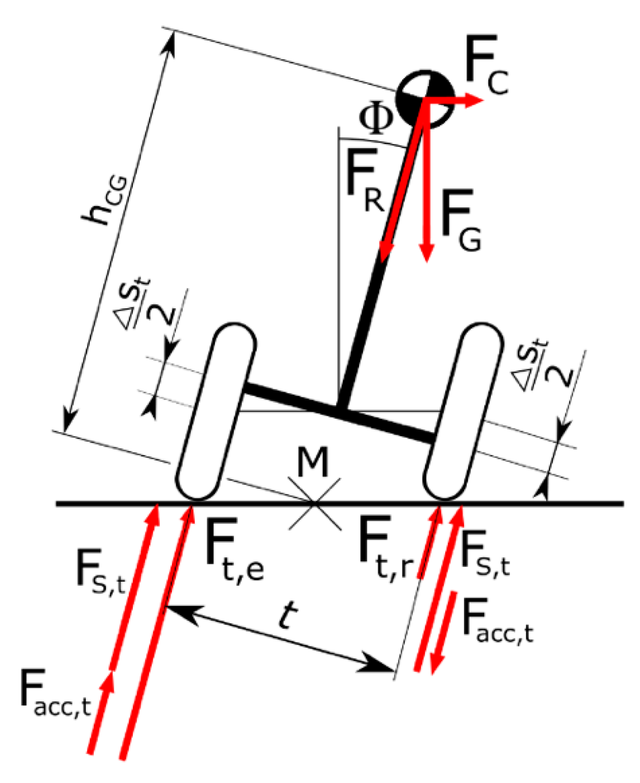
For the dimensioning of the actuators, the abstract model of the vehicle that is shown in Figure 4 was used. For simplification, the mass of the vehicle and the passenger were summarised as a point mass m in the CG. The device has a track width t and is tilted by the angle Φ to the vertical axis. To tilt the device, both actuators move the same travel Δ s t / 2 in opposite directions. In this case, the instantaneous centre of rotation M is at street level, centric between the wheels. The constant distance between the centre of rotation M and the CG is hCG. To fulfil the requirement that the passenger is free of lateral forces, the resultant force FR needs to point towards the centre of rotation M and is calculated by the superposition of the centripetal force F C and the weight force F G .
The static force F S , t per side is calculated as:
F s , t = F G + F C 2 = F R 2
The dynamic forces F a c c , t were calculated according to Equation (2) with the angular acceleration Φ ¨ and the inertia J described with the mass m and h C G :
F a c c , t = ± J t Φ ¨ = ± m h C G 2 t Φ ¨
The resulting total force for the retracting actuator F t , r and the extending actuator F t , e were calculated as:
F t , r = F s , t F a c c , t
F t , e = F s , t + F a c c , t
With an assumed total mass of 155 kg (80 kg for the passenger, 75 kg for the vehicle), a track width t of 0.49 m, a height h C G of 0.7 m, and a maximum angular acceleration Φ ¨ of 50°/s2, a maximum actuator force of 901 N was obtained.
Based on the calculations, two Thomson Electrak Pro linear actuators (PR2402-2A65) with Acme screw drives, 24 V electric motors, and 100 mm travel were chosen [19]. The linear actuators are capable of carrying loads up to 1125 N and have a maximum speed of 50 mm/s. They are equipped with built-in rotary encoders which provide relative information about the position of the actuator. The upper part of the actuators is fixed to the strut bearings, while the lower rods are connected to the wheel mounting plates. This enables the relative motion between the wheel and the frame when the actuator is operated. The self-locking actuators with Acme screw drives were chosen to prevent unintended lowering of the device when the actuators are not powered.

2.1.3. System Processing Units

The vehicle consists of one main computer and several micro-controllers to control different functionalities of the vehicle. Figure 5 illustrates the connection diagram of the system components. The main processing unit is the “UP-Board” [20]. This microcomputer is equipped with an Intel Atom X5 processor and 4 GB of RAM [20]. Ubuntu 16.10 is installed as the operating system, and the “Libmraa” library [21] is used for access to the hardware I/O.
Computationally intensive tasks of the autonomous positioning, navigation, and control of movement were processed by the UP-Board. Directly connected to the UP-Board are the Intel Realsense R200 3D-camera [22], the ultrasound distance-measuring sensors, an Arduino Due [23] microcontroller for the control of the powertrain, an Arduino Leonardo [24] for the control of the linear actuators, the receiver of the wireless remote, and a Wi-Fi access point for the remote access of the UP-Board.
The long-term release “Kinetic Kame” of the open source meta-operating system Robot Operating System (ROS) [25] runs on the UP-Board to enable the communication between the various functions and components of the vehicle.

2.1.4. Powertrain

Two brushless-DC (BLDC) motors SYM-36-50ZE are selected for the powertrain of the vehicle [26]. The motors have a single-sided shaft and a maximum torque output of 28 Nm with a nominal power output of 500 W, whereas the peak power output reaches 700 W and enables a maximum vehicle speed of approximately 20 km/h. The maximum required current is 25 A.
The vehicle is designed to have one electric motor on each side. The motor controller RoboteQ FBL2360 was selected as it is a dual channel controller that supports BLDC machines and sinusoidal control of the motors [27]. Sinusoidal excitation is smoother and results in a quieter operation and a more precise control as well as a higher efficiency due to less dissipation of heat. A serial connection allows sending commands and receiving data from the inverter. The motor controller supports a continuous maximum current of 40 A, a voltage of 60 V per channel, and the recuperation of brake energy. It can estimate the state of charge (SOC) of the battery and uses the hall sensors of the motor to provide odometry data.
A 36 V, 12s3p-battery pack with a capacity of 297 Wh was selected for the prototype. The cells were of the type ANR26650M1B with a LiFePO4 chemistry and support C-rates up to 28 [28]. The capacity was sufficient for test drives of about 3 km with an average speed of 11.5 km/h.
The control algorithm of the powertrain and self-balancing was executed on the Arduino Due and requires the lateral velocity of the vehicle and the balancing angle as inputs. Vehicle speed was obtained by the wheel odometry via the motor controller. The balancing angle was measured with an inertial measurement unit (IMU) of an Arduino 101 [29] which includes a gyroscope and an accelerometer.

2.2. Localisation

Scube is equipped with various sensors to determine its location. While local positioning is used to measure the relative movement of the vehicle, global positioning determines the absolute position on a 2D-plane.
The local positioning is conducted by in-vehicle odometry for dead reckoning and ultrasound-sensors and does not rely on external sources of information. The two wheels of Scube are arranged on a single axis with a differential steering system. The odometry relies on the revolution speed, the difference of the revolution speed of the two wheels, the wheel radius, and the distance between the two wheels, the so-called track-width. In the case of Scube, wheel revolutions are measured by the motor controller which evaluates the information of the hall sensors that are built into the motors. For the detection of objects in the near proximity of the vehicle, two rear- and two front-facing ultrasound-sensors of the type HC-SR04 are built into the Scube [30]. The sensors have a range of maximum 4 m and have a measuring angle of 15°.
For the global positioning, a landmark-based approach with an Intel Realsense R200 3D-camera [22] was implemented. The Intel Realsense R200 camera is equipped with two infrared (IR) cameras to capture a 3D-image with a resolution of 640 × 480 pixels at a rate of 60 Hz. An additional RGB-camera provides a colour-image with a resolution of 1920 × 1080 pixels. The integrated IR-projector is designed for a range of up to 2.8 m, however longer ranges are possible with increased noise and inaccuracies. The camera is mounted on the front side of the vehicle below the footrest. The imaging algorithms are able to function despite the shift of the camera tilt during vehicle movement.
Landmarks are any objects in the environment of which the global position is known [31]. For this experimental setup, QR-codes were used as landmarks. By recognising and measuring the distance to the landmarks, the position was calculated by trilateration. Trilateration requires three known points in space, however for the presented use case, the recognition of two points is sufficient for the positioning on a 2D-plane which results in two possible locations. Figure 6a illustrates how the correct location is determined by a logical check if the calculated location is within the perimeter of the map and by comparing the relative position of the two landmarks from the video stream of the camera. If more than two landmarks are visible to the camera at the same time, an algorithm decides which two landmarks are most suitable for positioning. The decision is based on the distance between the landmark and the vehicle as well as the distance between the landmarks to avoid unfavourable angles for 2D-trilateration.
Besides the position, the heading of the vehicle is required. The orientation is calculated by using the pinhole-camera model [32] which is shown in Figure 6b. The heading is described by the angle α between the x-axis of the local coordinate system to the x-axis x G of the global coordinate system. The camera only returns the orthogonal distance to the plane of the focal point. With the specifications of the focal length and the camera image size, the distances | P S 1 | and | P S 2 | are determined. The landmarks S1 and S2 are projected to the plane of the camera image ( S 1 and S 2 ) and are set in relation to the mid-point H’ of the camera image to determine S 1 H , S 2 H and the point H. The obtained vector P H represents the local x-axis of the vehicle and is used to calculate the vehicle heading α.

3. Results

3.1. Structure/Body

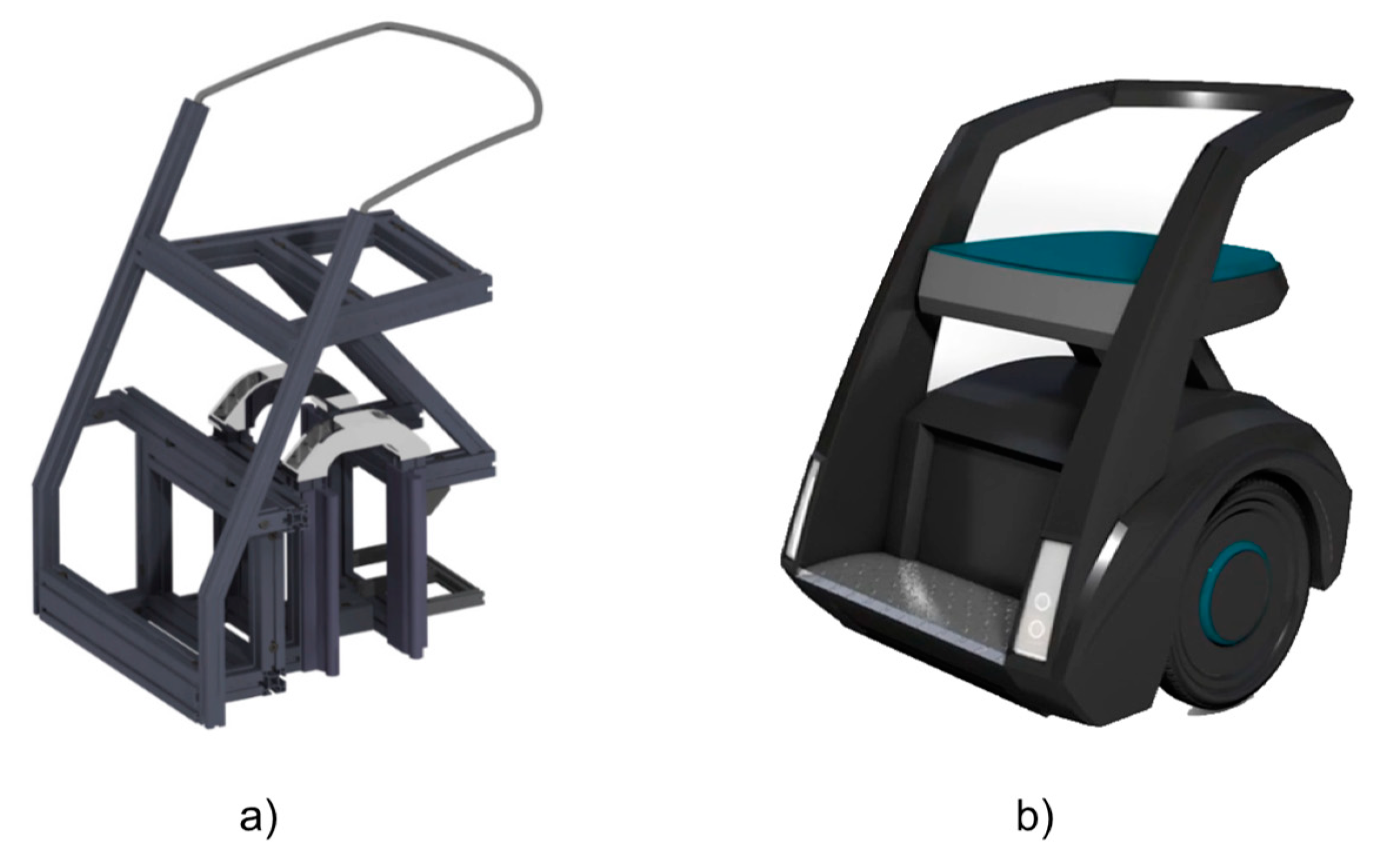
The load-bearing structure of the device is mainly made of square aluminium profiles (Figure 7). The profiles are joined in various positions and angles by connectors which can endure tensile forces of up to 10 kN [33]. The main frame is made of 40 × 40 mm and 30 × 30 mm aluminium profiles. The strut bearings take the load of the actuator forces and are milled out of aluminium. The backrest is made from a 12 mm aluminium rod to provide both strength and a curvature to increase the comfort of the backrest.
The outer shell of the vehicle is made from 3D-printed parts with a maximum thickness of 2 mm. A hexagon reinforcement structure was incorporated into the 3D-printed parts to increase their stiffness.
Figure 8 displays the final dimensions of Scube. The rigidity of the aluminium frame is sufficient to carry a person, while the lowering mechanism allows for improved accessibility. When the vehicle is in the lowered position, the whole bottom of the vehicle rests on the ground to provide a stable platform for ingress and egress that is comparable to a wheelchair. The reduction of the thickness of the shell to 2 mm reduced the costs for 3D-printing, and the hexagon structure provides sufficient strength, even for the larger parts, e.g. fenders. The total weight of the prototype is 74 kg.

3.2. Simulation of the Tilt Mechanism

A multi-body simulation of the vehicle concept was conducted to evaluate the influence of the tilt mechanism on driving behaviour. The multi-body simulation was set up to determine the maximum achievable lateral acceleration during a turn. A predefined route was generated with an increasingly reduced radius (Figure 9a). The vehicle was simulated with a constant speed of 2 m/s. The simulation was run until the vehicle started to deviate from the route due to slipping or after tumbling. Figure 9b shows that the vehicle without the tilt mechanism enabled can reach a maximum lateral acceleration of 2.5 m/s2 before toppling over. Figure 9c displays the result of the vehicle with the tilting enabled. A maximum acceleration of 6.8 m/s2 was achieved without the vehicle tumbling over.

3.3. Vehicle Performance

After acquiring map and location data, the vehicle waits for user input about the next destination. Once the destination is entered via a website-based user interface, the path from the current position is calculated and the vehicle turns on the spot into the direction of the first waypoint. After the correct initial heading is reached, the vehicle smoothly accelerates to a configurable driving speed and follows the pre-calculated path. At the destination point, the vehicle is stopped and waits for the next destination input.
If any obstacle is detected within approximately 0.5 m, the vehicle stops. After a waiting period, the vehicle starts to turn on the spot until it can pass the obstacle. If turning is not sufficient, the vehicle aborts the current route.
During travel, the expected current position provided by the local odometry is constantly compared with the actual measurement by the global localisation system. If the difference increases to over 0.4 m, a recalibration is executed where the vehicle comes to a stop. In order to prevent an oscillating driving course, a heading deviation of +/− 0.2 rad (approximately +/− 11.5°) is allowed.
Autonomous navigation and driving were conducted in a test area of 12 m × 5 m with three different destinations. The vehicle speed in the autonomous mode is limited to 0.3 m/s due to safety measures. The maximum rotational speed is set to 0.5π rad/s. The minimum rotation speed is 0.6 rad/s in order to overcome initial rolling resistance. Within the test area, the vehicle was able to acquire its position by landmark recognition and responded to passenger transport requests. Obstacle detection (e.g. people standing in the pathway) proved to be successful.

3.4. Localisation Results

The results of the localisation system are presented to demonstrate the achieved accuracy with the RealSense R200 camera system and the local odometry. The effect of the size of the QR-code is studied, then the accuracy of the global localisation is measured. Further, the accuracy of the vehicle odometry is tested with a pre-defined path. Finally, the results of an autonomously followed path are shown.
The QR-codes that were utilised for landmark localisation were printed full-page on different paper sizes ranging from DIN A1 (594 mm × 841 mm) to DIN A4 (210 mm × 297 mm). Due to the limited resolution of the camera system of 640 × 480 pixels, identification and recognition of the landmarks are only possible within a certain range to the landmark depending on the size of the QR-code, as shown in Table 1. Landmarks printed in DIN A1 size are recognisable up to 7–8 m, while landmarks printed on DIN A4 can only be recognised up to 2 m.
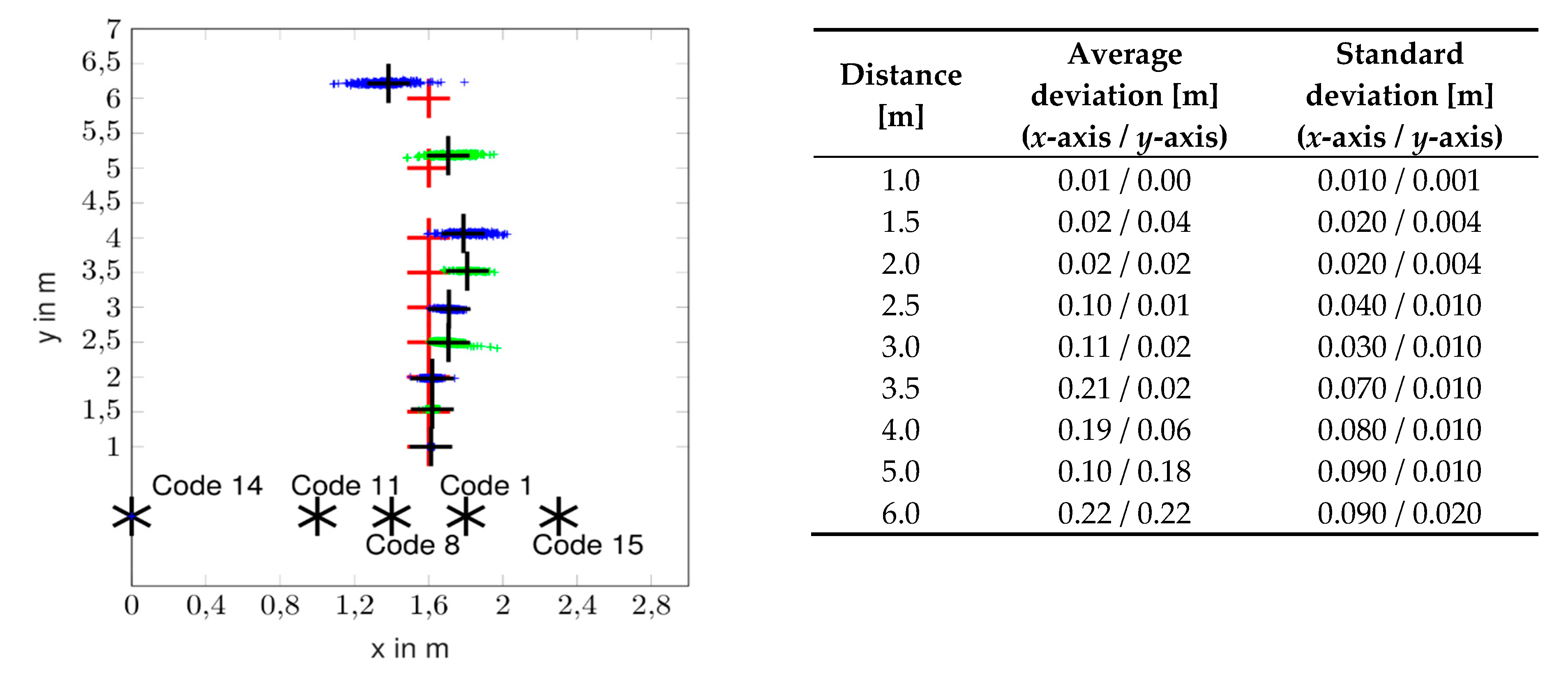
Besides the recognition of the landmarks, the resulting accuracy of the localisation was measured and is shown in Figure 10. The setup that is displayed in Figure 10 contains five QR-code-landmarks which are aligned on the same plane and facing the same direction. The two outermost QR-code-landmarks (code 14 & code 15) have the size DIN A1, while the QR-code-landmarks in the middle (code 1, code 8, code 11) are printed in DIN A3 size.
The distance between the landmarks and the vehicle was increased from 1 m to 4 m in 0.5 m increments. Two further measurement runs were conducted at a distance of 5 m and 6 m. The red crosses indicate the true position of the vehicle. At each position, 100 localisation runs were conducted (blue and green marks) by the vehicle. The black cross indicates the averaged measured position. The results in Figure 10 show that up to a distance of 2 m, the accuracy in both the x- and the y-axis is high, and the standard deviation in x- and y-direction is less than 2 cm and 1 cm, respectively. With increasing distance, the accuracy decreases. At a distance of 6 m, the standard deviation in the x-direction is 9 cm while it is 2 cm in the y-direction. Overall, the accuracy of the distance measurement (y-axis) is distinctively higher than the measurement in the x-direction because the distance is natively measured by the 3D-camera, while the lateral position is calculated by triangulation and is more strongly influenced by measuring errors.
The overall accuracy of the local odometry system was examined by tracking the predefined route shown in Figure 11a. The vehicle was manually moved on a 4 m × 4 m box-shaped route (black) and the data of the internal odometry is plotted (blue). Figure 11b shows the course of the measured heading. In the final position, a deviation of 0.1 m (x-axis) and 0.2 m (y-axis) is measured. The final heading error is 0.037 rad, respectively 2.1°.
Finally, the overall functionality of autonomous driving was evaluated. Figure 12a shows the outline of the testing area with the dimensions of approximately 5 m × 12.5 m. For this evaluation, the initial position of Scube is measured (green cross) and a destination is transmitted to the vehicle (orange cross). The calculated track is a straight line (black dotted line), which helps to detect course deviations for this evaluation. Figure 12b displays an enlarged view of the test track and includes the waypoints (black crosses) calculated by the vehicle. As the vehicle follows the calculated track, it continuously tracks its position (blue line). In the beginning, a course deviation can be seen, which is because of the intentionally allowed course tolerance to avoid an oscillating driving course. The track correction occurring at the position (2 m|3.5 m) is explained by a recalibration of the localisation system after it detected a deviation between the positions provided by local odometry and the global localisation. Afterwards, the vehicle follows the calculated track until the destination. It stops short of the destination point to avoid excessive turning on the spot, which would cause discomfort for the passenger. The final position of the device is measured manually (red cross). The deviation between the calculated and the manually measured final position is −0.04 m in the x-direction and 0.46 m in the y-direction.

4. Conclusions and Outlook

In this paper, the development and implementation of an autonomous mobility device concept is presented. The electric vehicle is designed to be part of a fleet which can be ordered on-demand by customers via a mobile application for last-mile/short distance transport to improve connectivity to public transport systems. The system reduces the reliance on private vehicles and privately owned PMDs and increases the convenience of the commuting population.
The vehicle is designed as a self-balancing, two-wheel device which can carry one person comfortably in a seated position. The size of the vehicle is determined based on anthropometric measures of the European and Singaporean population. The two-wheel design reduces the footprint of the vehicle to enable travel on narrow roads and in congested areas. Driving safety and comfort are increased by a tilt mechanism which leans the vehicle into the turn and reduces lateral forces. The tilt mechanism consists of two independent linear actuators for a swift change of the tilt of the vehicle and additionally acts as a means to lower the vehicle to the ground for easy mounting/alighting. The effectiveness of the tilt mechanism on the dynamic driving behaviour is demonstrated by a multi-body simulation and substantially increases the vehicle stability during turns. Driving comfort is increased by the self-balancing system of the device because it keeps the passenger in an upright position, even during travel over inclined surfaces. Additionally, the calculation of the required tilt-angle based on the routing of the vehicle can potentially counter lateral forces on the passenger more effectively and with reduced latency compared to the existing tilting-devices which only react after the occurring acceleration has been measured. In successive studies, a user study with the vehicle should be conducted to evaluate the driving comfort, the driving speed, and the safety from a passenger’s perspective.
To enable autonomous navigation, a landmark-based localisation system based on a 3D-camera system was implemented which works in conjunction with the local odometry system. The 3D-camera system proved to be a feasible and affordable solution for navigation and localisation in situations where no localisation by GPS is possible, e.g. indoors. The accuracy is sufficient for the demonstrated purposes, however the occurrence of occlusion of the landmarks can impact the localisation accuracy. For the application of higher vehicle speeds, the resolution of the camera system should be increased to enable a greater viewing range. QR-codes were used as landmarks for the presented indoor-evaluation which could be replaced by natural landmarks with an improved camera system and also to reduce the occurrence of occlusion of landmarks. The algorithms are able to detect obstacles in front of the vehicle by analysis of the camera image and the information from the ultrasound sensors to prevent collisions with any objects. This contributes to increased safety in comparison to existing PMDs without any object detection systems.
The vehicle was realized as a functional prototype for demonstration and testing purposes. The selected construction with aluminium profiles and a 3D-printed shell fulfils the requirements regarding stability, the time required for the built-up, and outer appearance. The size of the vehicle footprint is similar to other PMDs with a one-axle, two-wheels setup, however it offers increased comfort because of the seated position for the passenger. The weight of the prototype is between the weight of the presented Segway and the Scewo PMD. For the realization of the prototype in mass production, a more integrated structure should be considered to reduce the overall weight of the vehicle.
The selected components for the control of the system allowed for flexible integration of the conceived functionalities. The principal functionality of the autonomous operation was demonstrated, however the real-life usage is still limited by technical constraints of the self-balancing, the electrical actuators, and the accuracy of the localization system. Further development of the vehicle functions needs to be carried out to increase the operating speed and the overall stability of the autonomous navigation functions.
Going forward, the presented concept shows a possible solution for the first/last mile problem and can contribute to improving the ridership of public transport to reduce the reliance on private vehicles for transport in megacities. Besides closing the gap for the first/last mile, the small footprint of the vehicle enables the vehicle to operate in other public areas, including airports and shopping malls, where longer walking distances could be reduced.

Author Contributions

Conceptualization, M.K., F.R., M.W., B.H., T.H., L.L.S., J.S.D.L., Y.L., V.M., M.L., W.X.R.T., and M.L.; Investigation, B.H., T.H., V.M., and M.L.; Methodology, B.H., T.H., L.L.S., J.S.D.L., Y.L., V.M., M.L., and W.X.R.T.; Project administration, M.K., F.R., and M.W.; Resources, M.K., F.R., Michael Wittmann, Y.J.J.H., and H.W.N.; Supervision, M.K., F.R., M.W., Y.J.J.H., and H.W.N.; Visualization, L.L.S. and J.S.D.L.; Writing—original draft, M.K., B.H., T.H., V.M., and M.L.; Writing—review and editing, F.R., M.W., A.O., and M.L.

Funding

This work was financially supported by the Singapore National Research Foundation under its Campus for Research Excellence and Technological Enterprise (CREATE) programme and by the German Research Foundation (DFG) and the Technical University of Munich (TUM) in the framework of the Open Access Publishing Program.

Conflicts of Interest

The authors declare no conflict of interest. The funders had no role in the design of the study; in the collection, analyses, or interpretation of the data; in the writing of the manuscript, or in the decision to publish the results.

References

  1. United Nations. World Urbanization Prospects. The 2014 Revision: Highlights; UN: New York, NY, USA, 2014; ISBN 978-92-1-151517-6. [Google Scholar]
  2. Polzin, S. Setting Expectations for Mobility as a Service. Available online: https://www.planetizen.com/node/90839 (accessed on 20 March 2018).
  3. Brooks, R.A. Seat for Self-Propelled Narrow-Track Vehicle. U.S. Patent No 5,857,535, 12 January 1999. [Google Scholar]
  4. Saeger, M.; Simon, M.; Valluri, A. Method for Operating a Tilting Running Gear and an Active Tilting Running Gear for a Non-Rail-Bourne Vehicle. U.S. Patent No 9,821,620, 21 November 2017. [Google Scholar]
  5. Ishii, S.; Yamano, I. Travel Device. U.S. Patent Application No 11/984,154, 19 June 2008. [Google Scholar]
  6. Yuji Hosoda, S.; Egawa, J.; Tamamoto; Nakmura, R.; Horiuchi, T. Mobile Robot. U.S. Patent 7,649,331 B2, 19 January 2010. [Google Scholar]
  7. Segway Inc. Our Story. Available online: http://www.segway.com/about/our-story (accessed on 23 October 2017).
  8. Segway Inc. Reference Manual. Segway Personal Transporter (PT) i2, x2. Available online: http://www.segway.com/media/1688/referencemanual.pdf (accessed on 23 October 2017).
  9. Scewo. Scewo Bro Brochure. Available online: https://scewo.ch/wp-content/uploads/2018/10/Scewo-Bro_A5_EN.pdf (accessed on 20 November 2018).
  10. Airwheel Unicycles. Airwheel X8. Available online: http://airwheelunicycle.com/Airwheel-X8 (accessed on 23 May 2018).
  11. Zoom Urban Transport. Zoom Stryder Electric Scooter. Available online: https://www.ridezoom.co/ (accessed on 23 September 2018).
  12. Scewo. Scewo Press Kit. Available online: https://scewo.ch/ (accessed on 20 November 2018).
  13. Andersen, H.; Eng, Y.H.; Leong, W.K.; Zhang, C.; Kong, H.X.; Pendleton, S.; Ang, M.H.; Rus, D. Autonomous personal mobility scooter for multi-class mobility-on-demand service. In Proceedings of the 2016 IEEE 19th International Conference on Intelligent Transportation Systems (ITSC), Rio de Janeiro, Brazil, 1–4 November 2016; pp. 1753–1760. [Google Scholar]
  14. Kleine ergonomische Datensammlung; Lange, W.; Windel, A.; Kirchner, J.-H.; Bundesanstalt für Arbeitsschutz und Arbeitsmedizin (Eds.) Praxiswissen Arbeitssicherheit; 13., aktualisierte Aufl.; TÜV-Media: Köln, Germany, 2009; ISBN 978-3-8249-1244-5. [Google Scholar]
  15. Chuan, T.K.; Hartono, M.; Kumar, N. Anthropometry of the Singaporean and Indonesian populations. Int. J. Ind. Ergonom. 2010, 40, 757–766. [Google Scholar] [CrossRef] [Green Version]
  16. Hatam, B.; Herrmann, T.; Medovy, V.; Merkle, L.; Lim, J.S.D.; Sim, L.L.; Lu, Y.; Ten, W.X.R. Team “Micromobility” Final Report globalDrive 16/17. 2017; Unpublished Results. [Google Scholar]
  17. DIN 18040-1:2010-10: Barrierefreies Bauen—Planungsgrundlagen—Teil 1: Öffentlich zugängliche Gebäude. 2010. Available online: https://nullbarriere.de/din18040-1.htm (accessed on 24 October 2017).
  18. Building and Construction Authority Singapore. Code on Accessibility in the Built Environment 2013. Available online: https://www.bca.gov.sg/BarrierFree/others/ACCESSIBILITY_CODE_2013.pdf (accessed on 24 October 2017).
  19. Thomson Industries. Pro-Series/Electromechanical Linear Actuator—Installation and Operation Manual. Available online: https://www.thomsonlinear.com/downloads/actuators/Electrak_Pro_Series_mnen.pdf (accessed on 24 October 2017).
  20. AAEON Technology (Europe), B.V. Up Board—Specification. Available online: http://www.up-board.org/wp-content/uploads/2016/05/UPDatasheetV8.5.pdf (accessed on 6 October 2017).
  21. Libmraa—Low Level Skeleton Library for Communication on GNU/Linux platforms. Available online: https://github.com/intel-iot-devkit/mraa (accessed on 2 June 2018).
  22. Intel Corporation. Intel RealSense Camera R200: Embedded Infrared Assisted Stereovision 3D Imaging System with Color Camera: Product Datasheet. Available online: https://www.mouser.com/pdfdocs/intel_realsense_camera_r200.pdf (accessed on 15 January 2018).
  23. Arduino, s.r.l. Arduino Due—Tech Specs. Available online: https://store.arduino.cc/usa/arduino-due (accessed on 15 January 2018).
  24. Arduino, s.r.l. Arduino Leonardo—Tech Specs. Available online: https://store.arduino.cc/usa/arduino-leonardo-with-headers (accessed on 15 January 2018).
  25. ROS ROS History. Available online: http://www.ros.org/history/ (accessed on 25 October 2017).
  26. dmg-movement. Motoren Übersicht. Available online: http://www.dmg-movement.de/Motoren.htm (accessed on 15 January 2018).
  27. Roboteq. Brushless DC Motor Controllers: FBL2360. Available online: https://www.roboteq.com/index.php/roboteq-products-and-services/brushless-dc-motor-controllers/324/fbl2360-detail (accessed on 15 January 2018).
  28. Linergy Engineering GmbH. Fahrradakku LiFePO4 6V/2,5Ah-25Ah aus A123 ANR26650 Zellen—A Version. Available online: https://www.linergy-shop.de/de/Fahrradakku-LiFePO4-36V-2-3Ah-aus-A123-ANR26650-Zellen---A-Version---315-425-1065.html (accessed on 15 January 2018).
  29. Arduino, s.r.l. Arduino 101—Tech Specs. Available online: https://store.arduino.cc/usa/arduino-101 (accessed on 15 January 2018).
  30. Ultrasonic Ranging Module HC—SR04. Available online: https://cdn.sparkfun.com/datasheets/Sensors/Proximity/HCSR04.pdf (accessed on 15 January 2018).
  31. Borenstein, J.; Everett, H.R.; Feng, L. Where am I? Sensors and Methods for Mobile Robot Positioning; University of Michigan: Ann Arbor, MI, USA, 2016. [Google Scholar]
  32. Computer Vision; Ikeuchi, K. (Ed.) Springer US: Boston, MA, USA, 2014; ISBN 978-0-387-30771-8. [Google Scholar]
  33. MayTec Aluminium Systemtechnik GmbH the MayTec Connection System. Available online: http://www.maytec.de (accessed on 15 January 2018).
Figure 1. Examples of various PMDs (Personal mobility devices): (a) Segway i2 Personal Transporter; (b) Scewo Bro [12]; (c) Airwheel X8; (d) Zoom Stryder EX [11].
Wevj 09 00048 g001
Figure 2. Body measurements according to reference [14,15].
Wevj 09 00048 g002
Figure 3. Display of the suspension and actuator system.
Wevj 09 00048 g003
Figure 4. Abstract model of the vehicle for the calculations of occurring forces on the actuators.
Wevj 09 00048 g004
Figure 5. Overview of the system components.
Wevj 09 00048 g005
Figure 6. (a) Localization by recognition of landmarks; (b) Calculation of heading by the pinhole-camera model.
Wevj 09 00048 g006
Figure 7. (a) Mainframe of Scube; (b) Scube with attached shell.
Wevj 09 00048 g007
Figure 8. Exterior dimensions of the vehicle.
Wevj 09 00048 g008
Figure 9. Simulation of occurred acceleration during a defined turn (a) without tilting (b) and with tilting (c).
Wevj 09 00048 g009
Figure 10. Distribution of localisation measurements using multiple landmarks.
Wevj 09 00048 g010
Figure 11. (a) Comparison of the predefined driving route (black) with data recorded by onboard odometry (blue); (b) Recorded heading during travel over the predefined route.
Wevj 09 00048 g011
Figure 12. (a) Overview of the testing area and the test track; (b) Enlarged detail of the planned track (black dotted line), planned waypoints (black crosses), start position (green cross), destination (orange cross), internally computed track (blue line), computed destination position (blue cross), manually measured final position (red cross).
Wevj 09 00048 g012
Table 1. Influence of QR-code landmark size on recognition distance.
Size of QR-CodeMaximum Distance for Recognition
DIN A17–8 m
DIN A25–7 m
DIN A33–4 m
DIN A42 m