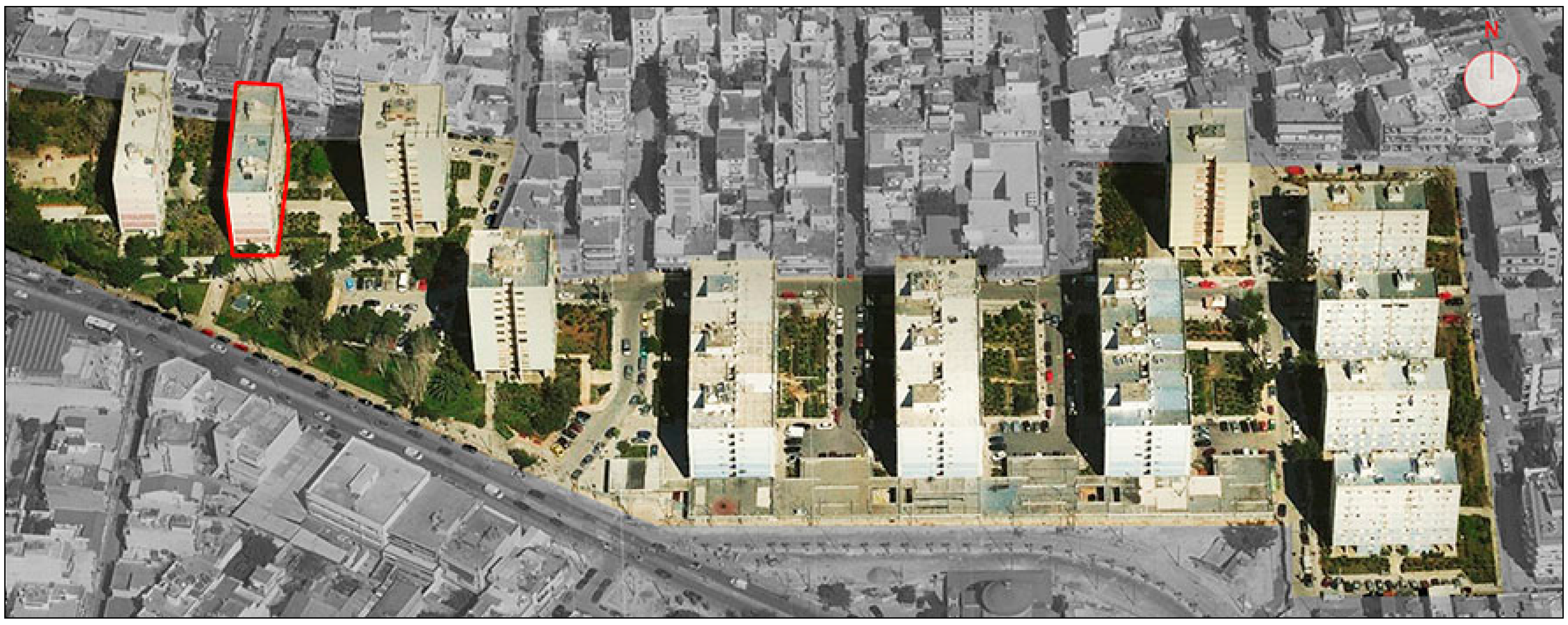
One of Pro-GET-onE feasibility studies was located in Greece, more precisely in Peristeri, a suburban municipality of Athens in the Attica region. It has a population of 146,000 inhabitants and is located at a distance of 5 km in the western part of Athens and is the biggest and the second densest suburb of the Attica region. The pilot case of the Peristeri compound (Athens, Greece) is a typical social housing development from the late 1960s.
The main structure of the buildings is reinforced concrete (pillars and beams), concrete slabs, and hollow brick external walls. This is a typical construction typology and is globally presented in all Attican suburbs and the city center. It also has a common structure with similar building blocks all over Europe.
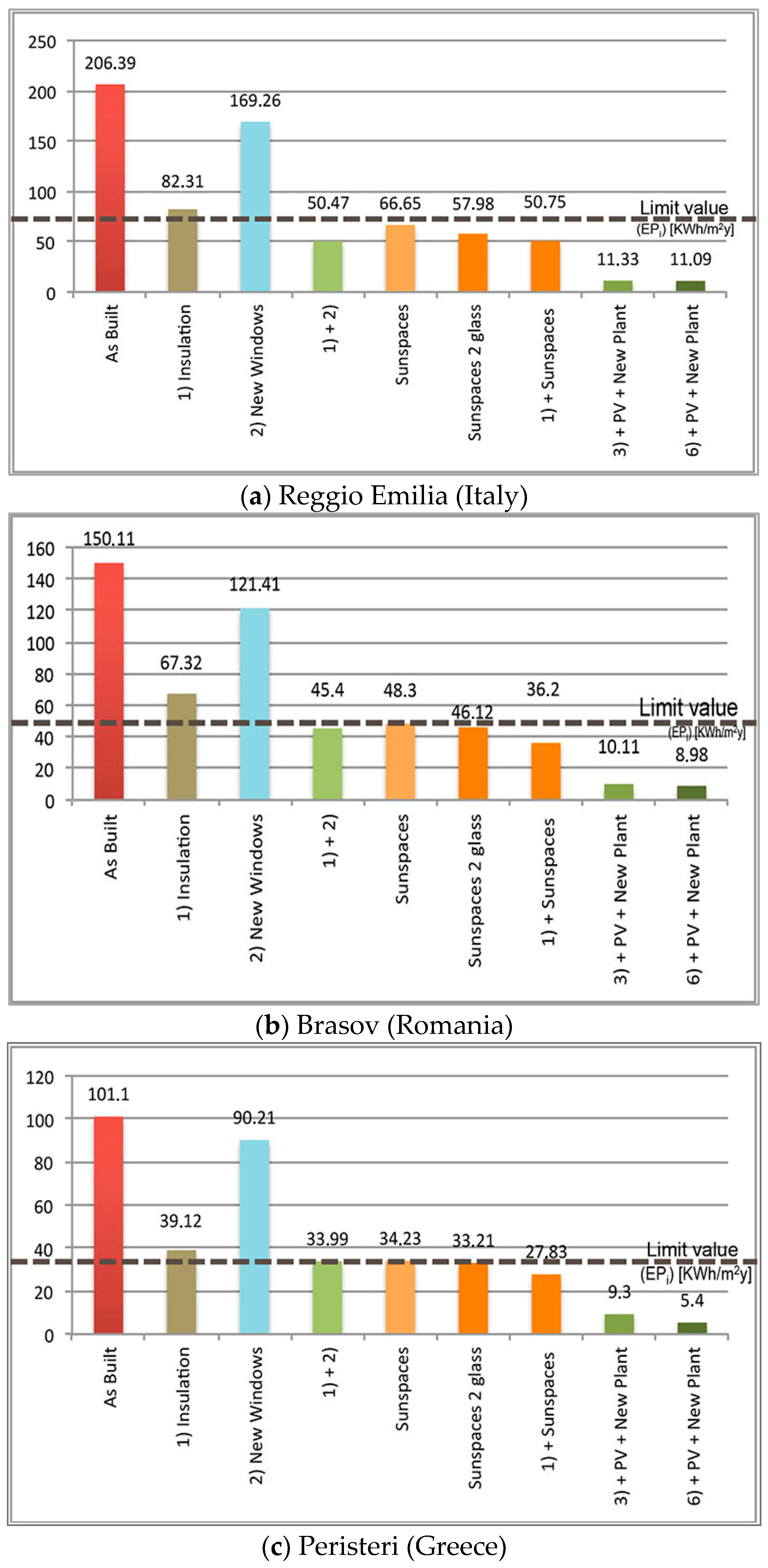
Each building block has a centralized heating system plant. Existing windows are made of an aluminum or wooden frame with single glass although part of the external windows has already been replaced. The energy performance of the buildings is very low and in need of energy retrofit (160 Kwh/m2 × y (winter)/110 Kwh/m2 × y (summer)).
A retrofitting project that can guarantee a high level of energy performance can be a source of savings for the inhabitants and municipalities. High-energy costs have led the majority of the residents to choose alternative and less efficient heating solutions such as kerosene, electricity, coal or wood, increasing environmental pollution. The large number of standardized multi-apartment residential blocks leads to the possibility of adopting similar solutions to improve energy efficiency, thus ensuring an economy of scale.
The application of the project could guarantee a substantial energy improvement and would not be limited to this aspect. As we have already seen, the benefits of the “GET” structure would span the improvement of earthquake performance, which is a fundamental aspect to increase the value of the intervention.
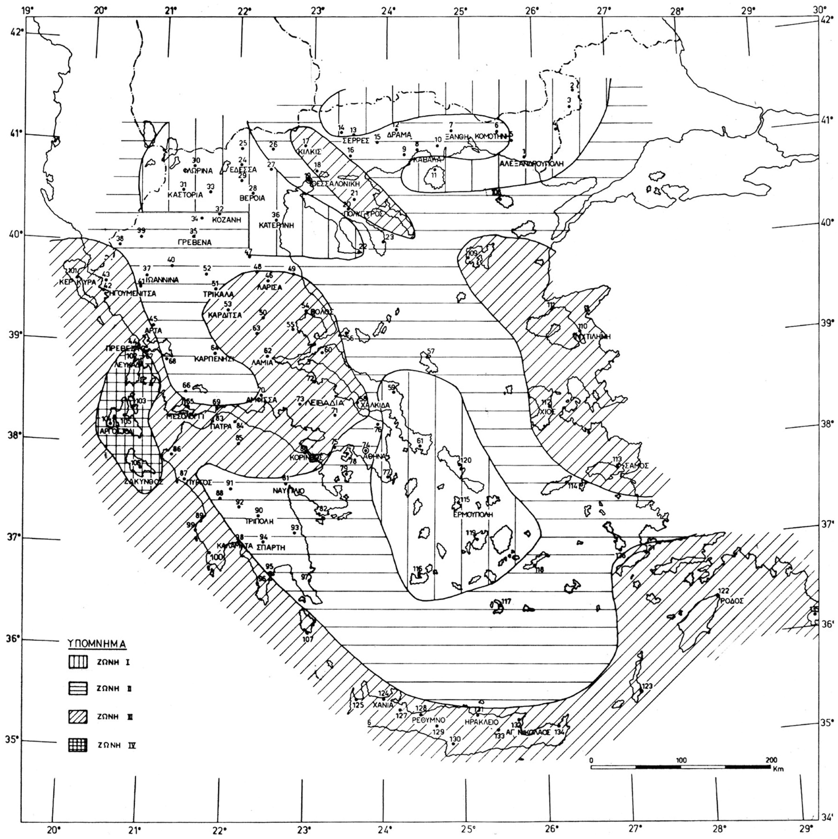
Following this classification, Athens is located in Zone II with an anchor acceleration value of 0.16 g to be applied in the definition of the response spectrum to carry out the checks. In the analysis phase, the structure was subjected to a greater acceleration to highlight the results of the system.
3.1. Seismic Analysis
The building is from the 60s and has a longitudinal shape with a reinforced concrete structure. It was built in the period after World War II when there was a “boom” in construction of this type in the suburbs of all European cities. Unlike the Italian case, despite the construction period, this building testifies to the already present conception of seismic design, as demonstrated by the dimensions of the structural elements.
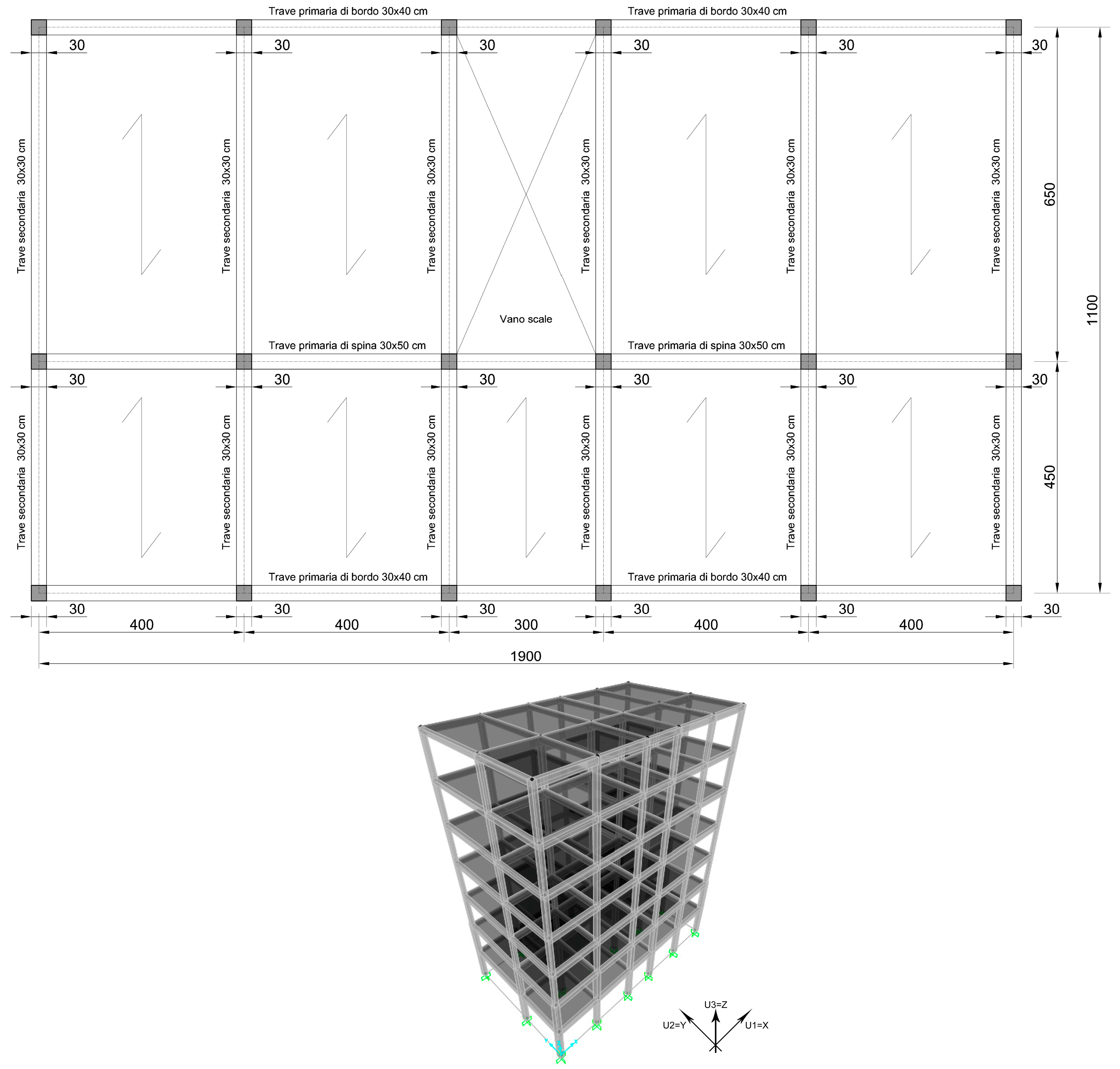
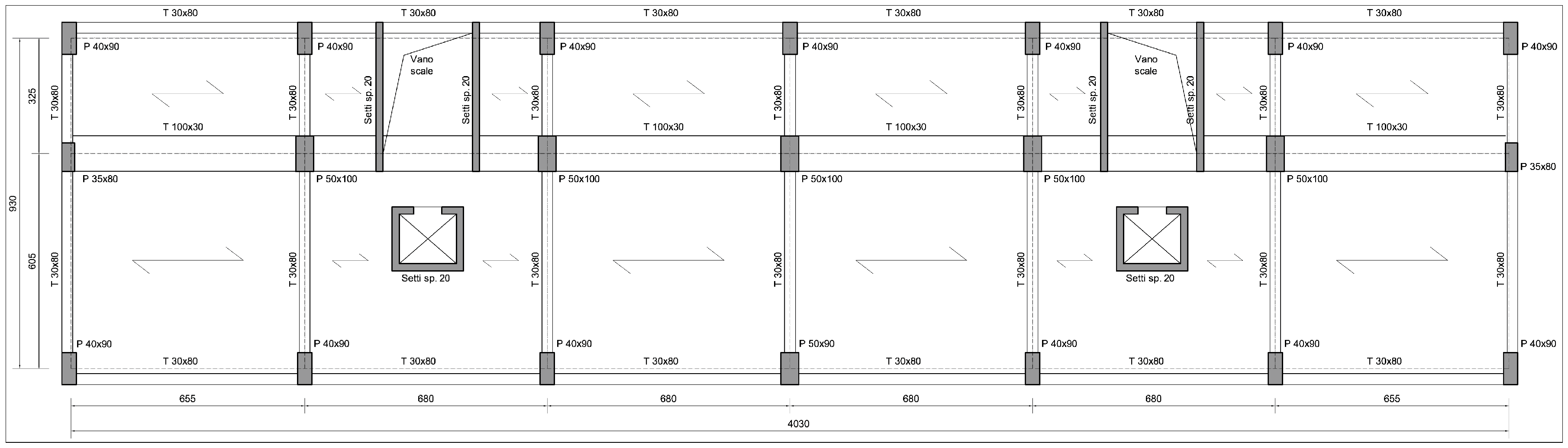
It has a reinforced concrete structure with a mainly longitudinal development. It is composed by frames arranged in the direction of the shorter side. The concrete slabs lie on these frames. There are also two secondary frames on the edges and one in the middle characterized by the presence of flat beams. A twenty-centimeter reinforced concrete wall can be identified near the stairwells and the elevators.
The original geometrical and architectural data of the initial state were provided to the authors by the municipality of Peristeri. The dimensions and the structural schemes of the beams were obtained by photographic survey, while those of the columns and of the concrete walls were taken from the original architectural plans.
The structure is composed of six units with an average span 6.60 m in the longitudinal development, (the two external ones are of about 6.55 m while the four internal ones have a distance of 6.8 m).Transversely, the space is divided into two zones of a spacing of 3.25 m and 6.05 m. On the ground floor is the
pilotis while the six upper floors are dedicated to residential units (
Figure 10).
The simulations carried out were done with finite elements software SAP2000 [
15]. Linear dynamics (modal analysis with response spectrum) was chosen for the seismic analyses.
Table 5 shows data regarding the modeling phase, while
Table 6 indicates the seismic parameter for the response spectrum definition for the analyses and for the verifications.
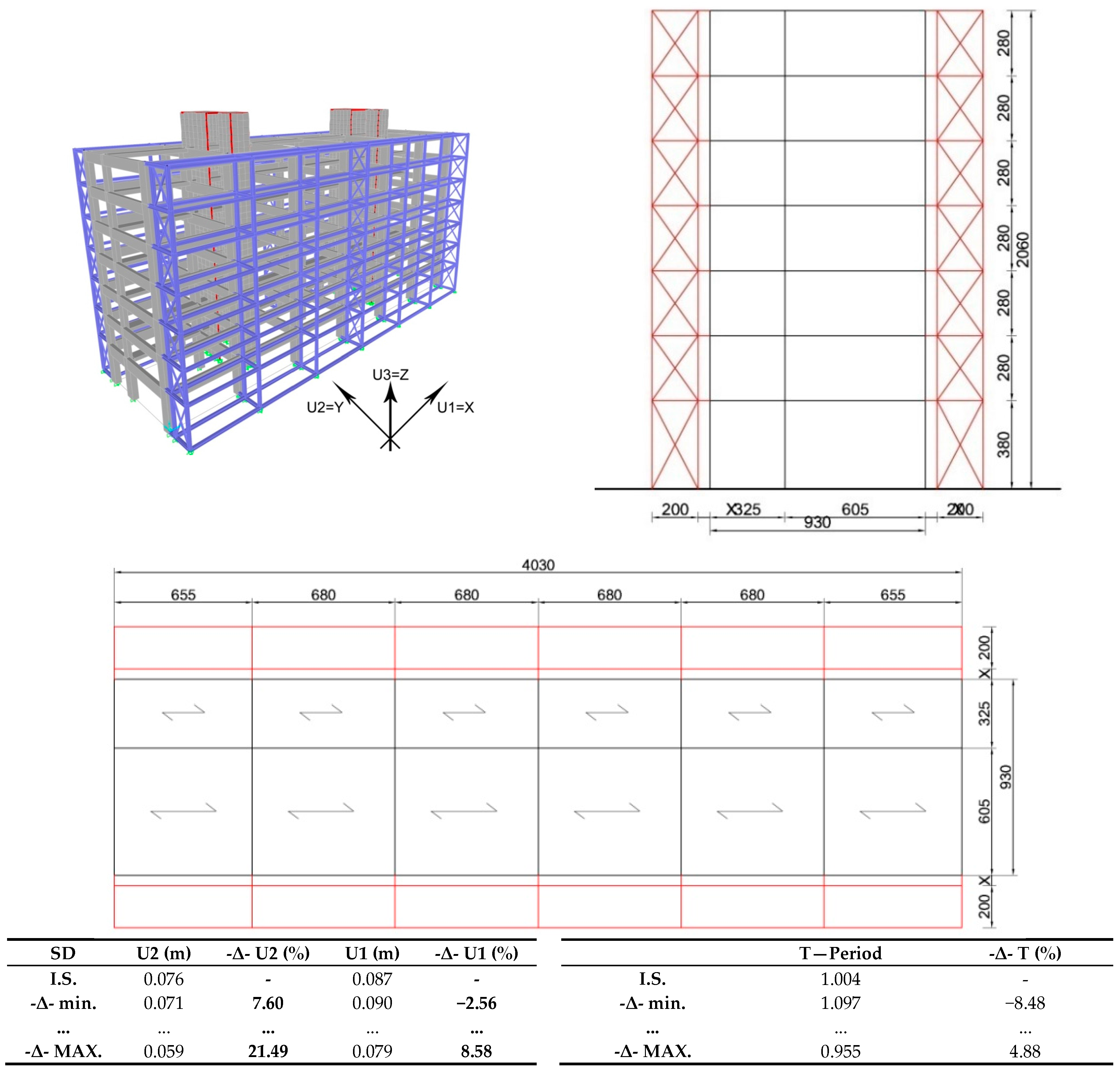
In this section, we refer to two parameters regarding the results of the proposed structure: the absolute displacements at the top of the existing building, and the period of the structure.
The assumed structure composed briefly as shown above in the structural plan was modeled in SAP2000 [
15] through the use of linear elements (for beams and columns) and bilinear elements, shells (for concrete walls).
Figure 11 reports the main results of the linear dynamics analysis of the initial state.
Regarding the building’s seismic response, it is evident that it was designed to withstand seismic actions. In fact, despite the high level of the applied seismic action, there are limited displacements considering the height of the building. From the analyses carried out after the application of the “GET” system, it was therefore predictable to obtain very limited improvements when compared to the virtual cases previously described.
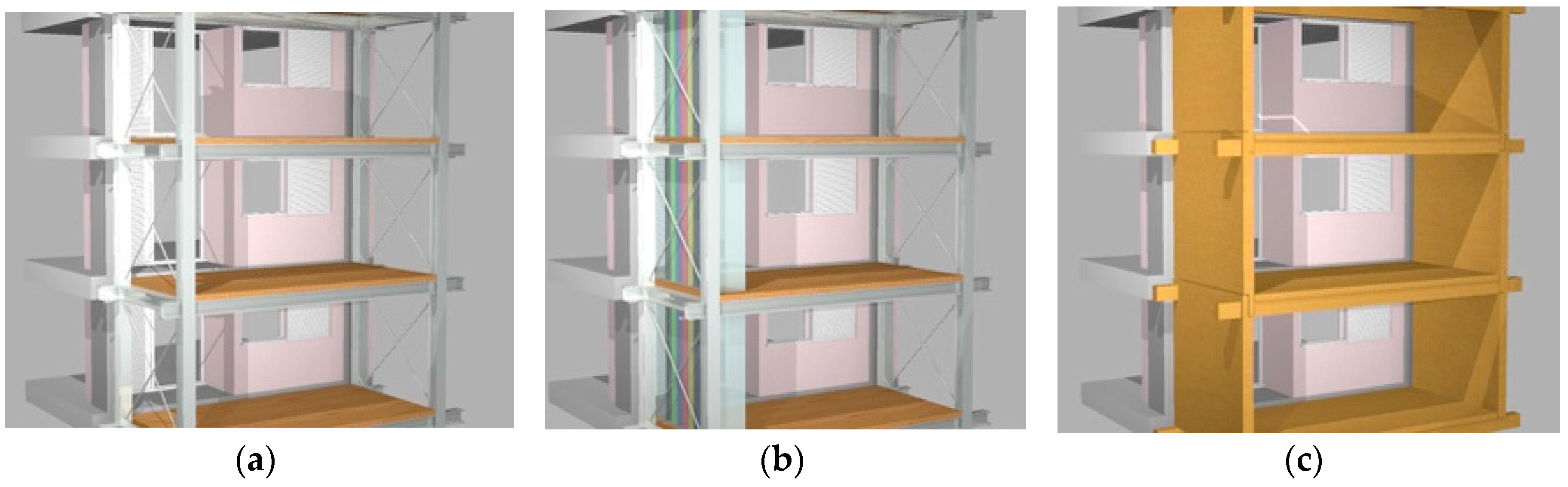
The additional structure provided for the project consists of steel frames (columns and beams) for each floor, braced in the transversal direction due to the architectural requirements, and linked to the joints of the existing reinforced concrete frame (created from the intersection of beams and pillars). These frames are also connected in the longitudinal direction to create a spatial frame interconnected with the existing structure.
The depth increase of the smaller side of the building allows it to obtain more regularity in plan and to increase the stiffness, causing a reduction of displacements and internal forces in the elements.
The first steel structure solution (solution A, shown in
Figure 12) is continuous on the whole façade and presents transversal bracing at the middle and at the ends of the new structure.
Here we show the results due to the variation of the profiles that compose the structure (columns and beams). The improvement is calculated on the comparison before and after the application of the steel structure.
In this phase, several profiles were examined initially by varying the type at the same weight and subsequently by varying the type with the same height in order to obtain a general scheme. Based on these analyses, the incidence of the profiles has been verified.
It has been verified that the choice of the columns is decisive in the improvement and that the types of profiles that have a different inertia module in the two directions (e.g., IPE type) are inconvenient. In fact, in some cases, these profiles aggravate the displacements in the longitudinal direction. The other way around, profiles with equivalent stiffness or almost in the two directions are ideal for the intervention (HE and pipes). Clearly, HE profiles are preferable during the assembly procedure.
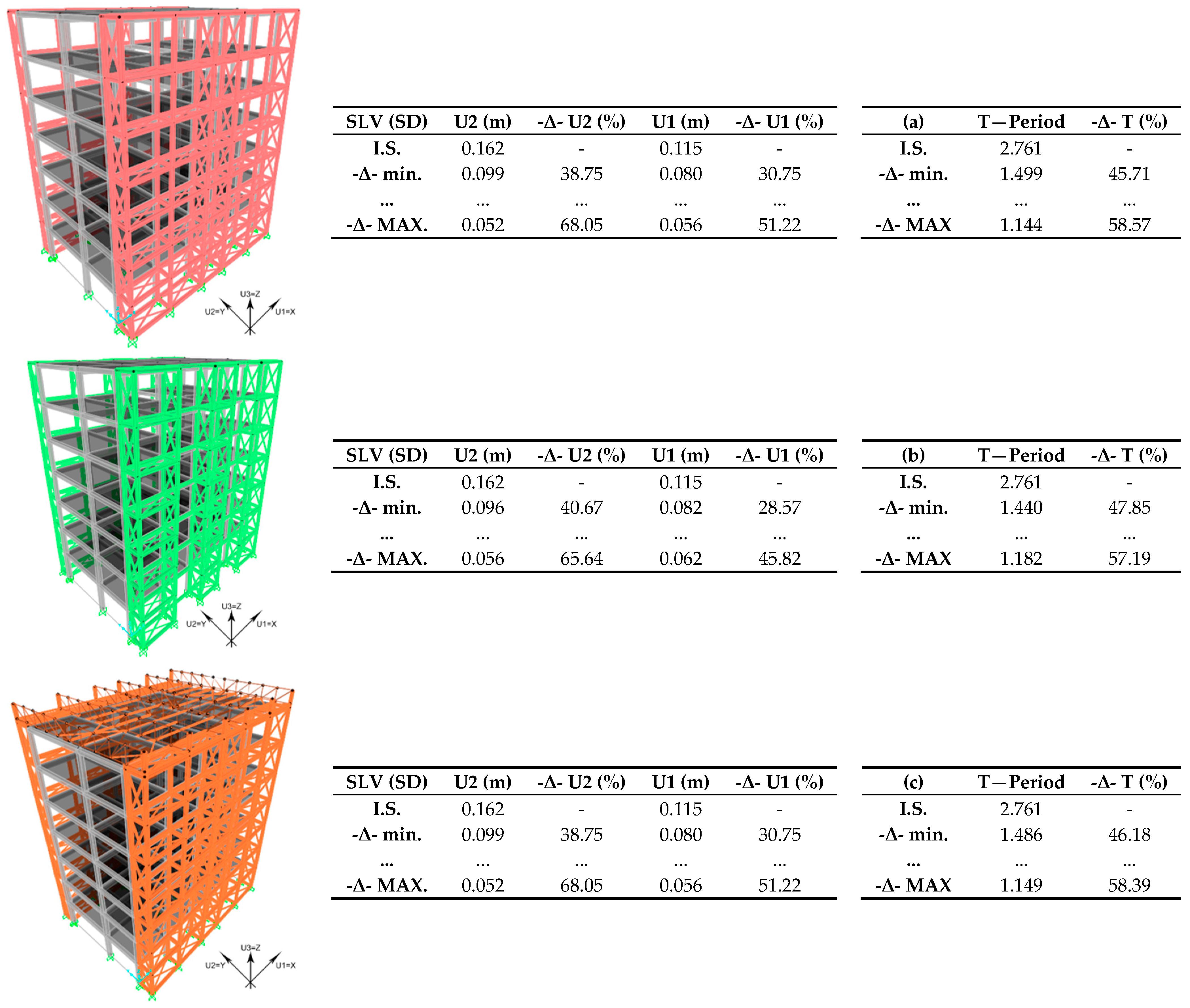
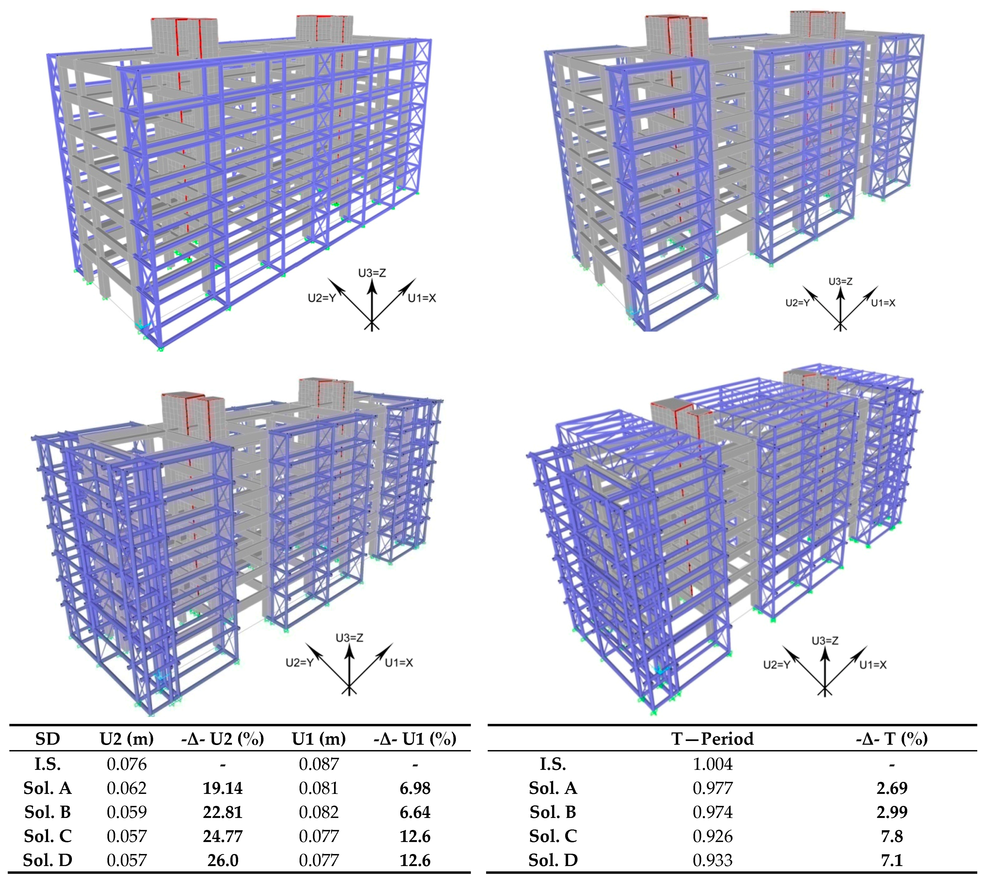
The following analyses were carried out with the use of HEB 240 and Φ323.9/12 profiles. The results obtained using the last indicated profile are shown below, but follow different structural configurations as described in
Section 2.1:
A—Continuous addition to the longitudinal façades. It presents transversal bracing at the middle and at the ends of the new structure.
B—Alternate addition to the longitudinal façades. It presents transversal bracing at each span.
C—Alternate addition to the longitudinal façades combined with continuous addition on the transversals.
D—Alternate addition to the longitudinal façades, continuous addition on the transversals plus top connection with reticular beams.
Looking at the results obtained from the analyses (
Figure 13), design solution B had more diagonal bracing on the transversal planes and smaller displacements in the Y (U2) direction. Moreover, this solution turned out to be the least expensive by using lower quantities of steel in the project.
Solution C had an alternate addition to the longitudinal facades and a continuous addition on the transversals. The addition on the short sides was not connected to the existing structure, but only to the longitudinal ones. This helped to improve the performance of the structure in both directions to the detriment of an increase in costs countered by a small increase in useful area.
The last solution of the analysis phase provided a superior connection between the lateral additions, which produced a decrease in displacements against an increase in the period due to the rise in building height.
Finally, by also combining an assessment of the costs of the structure, a check of the elements of the new steel frame was carried out. In this phase, all the profiles constituting the new structure were defined and differentiated based on internal stress and on the cost calculation dependent on the weight of steel. The aim was to find a fair compromise between the construction costs and performance in terms of improvement achieved on the existing structure.
Another fundamental aspect was represented by a parallel evaluation of the added surfaces due to the volumetric external addition. The added value given by these areas reduced the expenses.
As reported at the beginning of the section regarding the verifications (Eurocode 3 and 8), the seismic load relating to Athens was used based on the EAK2000 [
14].
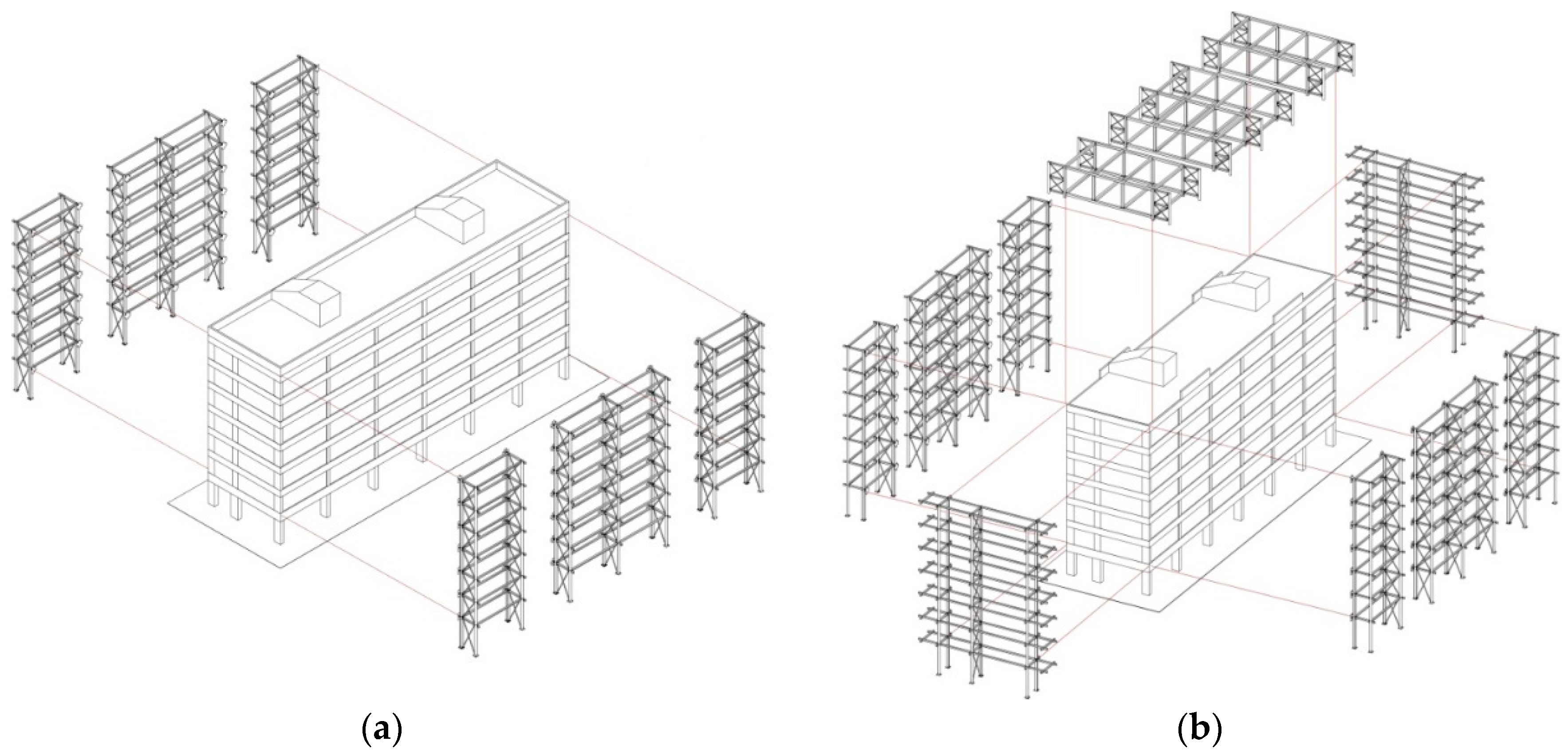
Two structural solutions were considered due to different benefits:
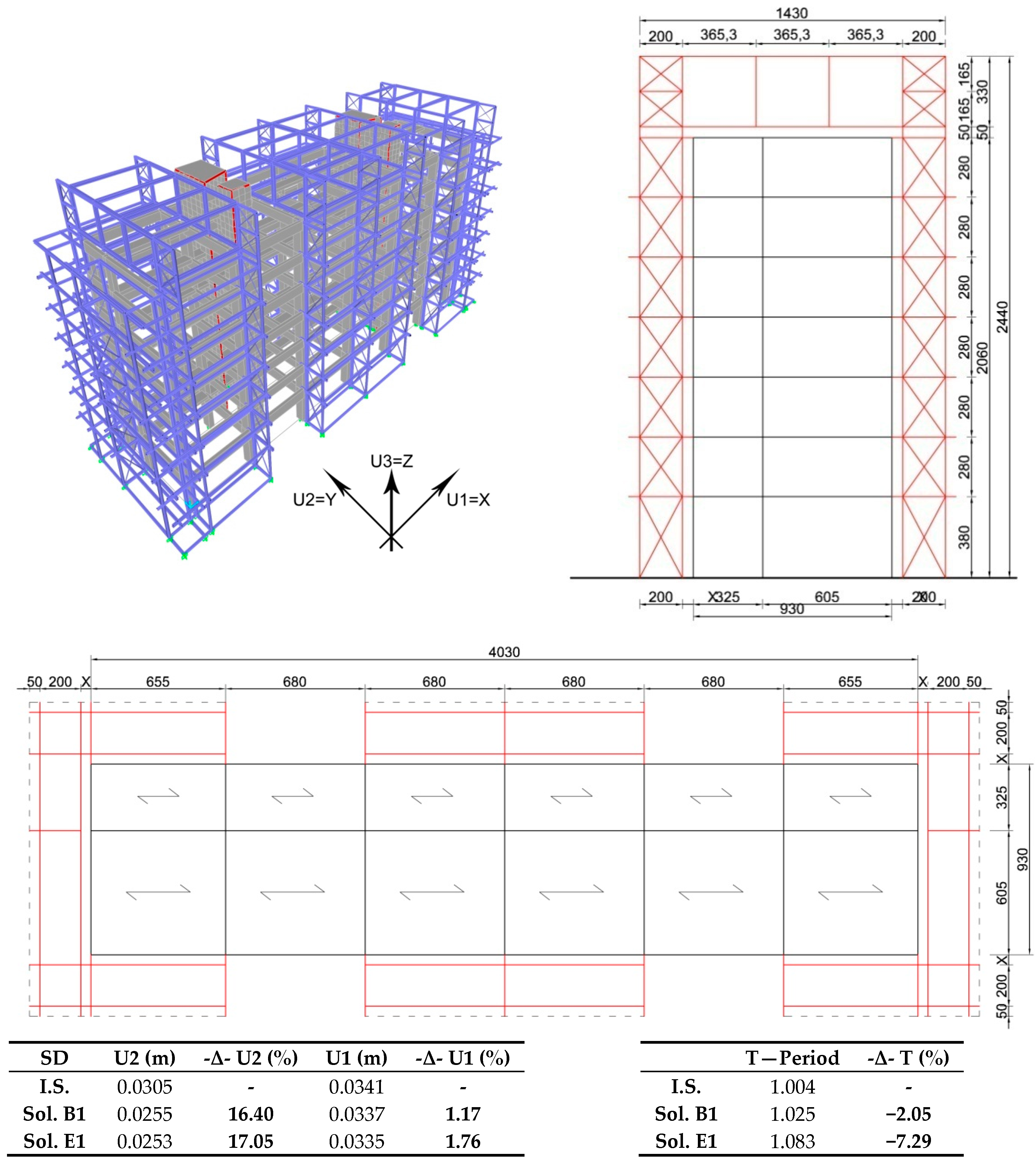
B1—Alternate addition to the longitudinal façades (
Figure 14a). This solution involves the greatest performance benefit with minimal cost; however, it has a small contribution in terms of added area.
E1—Alternate addition to the longitudinal façades, continuous addition on the transversals plus top connection with Vierendeel beams (
Figure 14b). A different solution to the previous ones is illustrated below. Thanks to the possibility of raising the structure of a floor, this allows the greatest contribution in terms of added surface, a higher cost with equal performance benefit on displacements.
Regarding the design solution E1,
Figure 15 shows the schemes and the analyses output data.
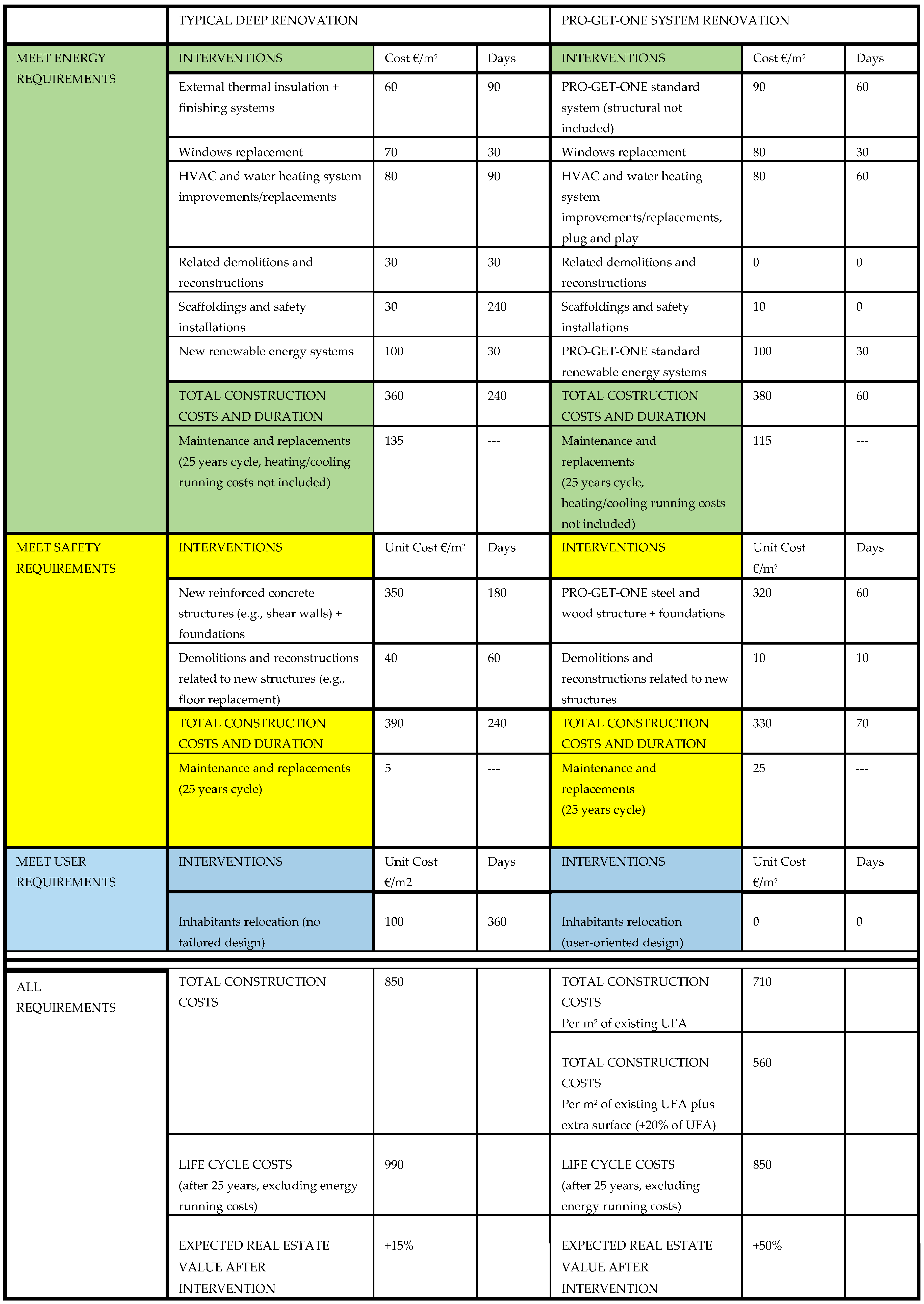
Furthermore, the actual benefit that the Pro-GET-onE implies for the existing construction in terms of earthquake response was verified. Various design solutions were analyzed that involved variable quantities of added area, and used material (steel), which produced different responses to the earthquake. Overall, an improvement in terms of displacements was always obtained due to the increase in stiffness given by the addition of the new structure. The analysis carried out initially focused on the maximization of the benefits on the existing construction and afterwards, on the most valid design solutions (in terms of performance), a compromise has been proposed to ensure a seismic improvement at the lowest possible construction cost (considering only the structural components of the project).
Two proposals have been made (B1 and E1), which guarantee good performance in terms of transversal displacements (16–17% improvement), a substantial indifference for the displacements in the longitudinal development of the construction, and a large increase in added surface that reduced the cost of construction. Additionally, the assessments on the construction cost showed that both solutions had the same cost per square meter of added surface.
In conclusion, as far as regarding seismic safety, this case study verified that the GET system could provide improvements even for buildings that have already been designed with an adequate performance for horizontal loads. Certainly, the value of improvement for the previous buildings mentioned, was limited when compared to the structures that have been designed to withstand only vertical loads, in which cases the GET system could prove better safety results.
3.2. Architectural Verification—The Abacus
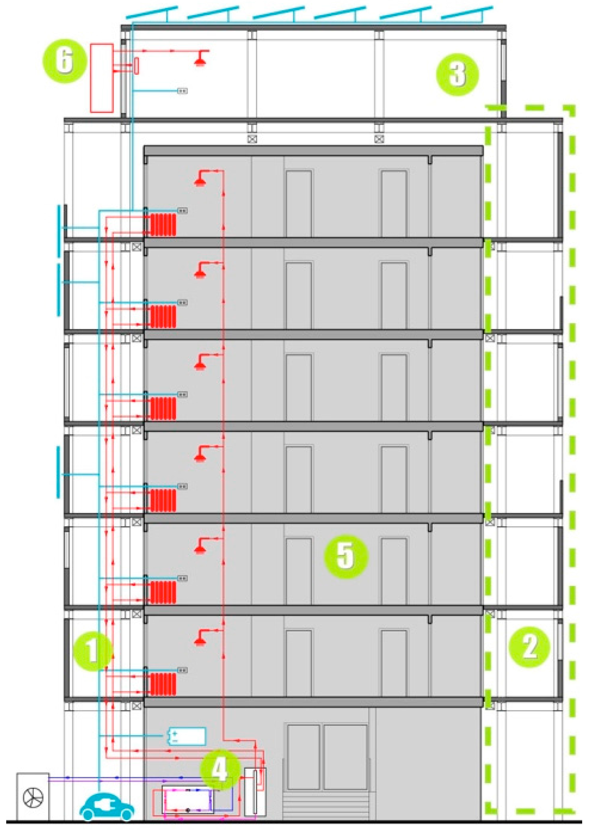
Parallel to the seismic improvement conferred by the external steel structure, a series of possible architectural solutions have been developed to incorporate the skeleton initially formed by the single structural component. In this phase, it is necessary to consider several factors that determine the appearance and the way of using the additional space by choosing constructive solutions, materials, and the functional types. Highlights of this design typology include the versatility of the additional volumetric units in relation to the possibilities and the choices of the user, and the constant search of energy improvement aimed at the goal of bringing the existing building toward the nZEB.
Currently, one of the main shortcomings of deep retrofitting towards nearly zero energy is that they generally rely on separate clusters of technologies that are difficult to integrate. To overcome these barriers and create a roadmap for cost effective renovation through a well-balanced strategy of mass customization, the research project has envisaged an integrated modular system, composed of components manufactured off-site, that can be customized and optimized for different cases in a user-oriented perspective (by adding balconies, loggias, sunspaces according to the users’ needs and expectations). The integration of the system will focus on the interfaces between the different components to ensure their collective performance according to the project requirements. Standardized interfaces will also ensure the flexibility of the system, as different components can be interchanged and adjusted as a function of different climate conditions and urban context, as well as according to the inhabitants’ requirement.
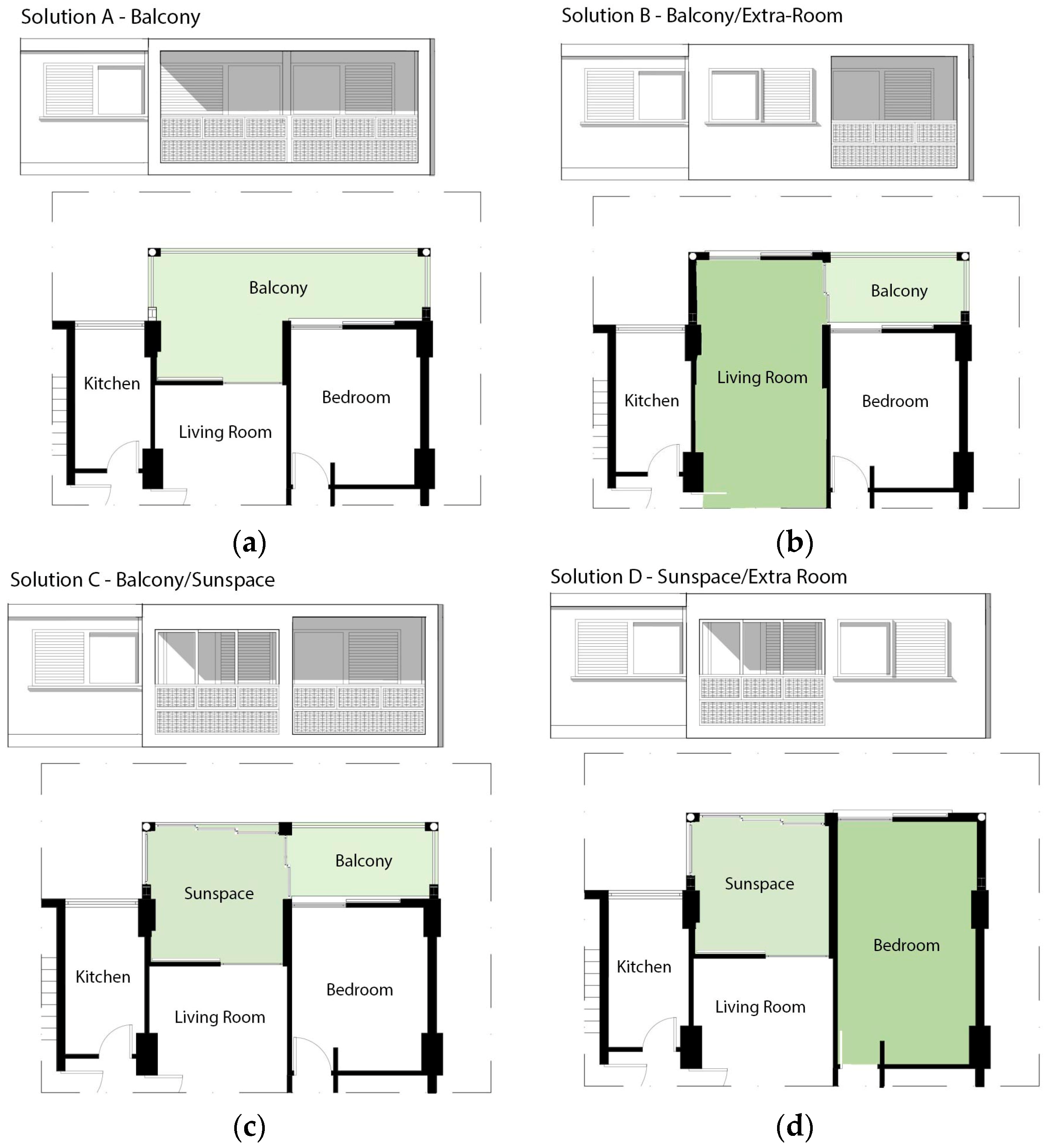
Regarding the Greek building, different architectural hypotheses have been realized. In each of these solutions, several additional volumetric units were hypothesized and divided into three functional types: sunspace, extra-room, and balcony.
Figure 16 shows a possible functional and therefore architectural variation of the same external volumetric addition.
Performed cost-benefit analysis in a large set of reference buildings in the context of another EU project ABRACADABRA [
16] that considered the hypothetic investment in additional units on top of GETs showed that the potential economic gains obtained through the sale would largely compensate the energy retrofit cost including RES to set the energy demand of the whole building to zero. The GET system, in fact, could be used to support additional loads on top of buildings that were not structurally conceived for addition. This aspect could implement and accelerate the market penetration of deep renovation within the private sector, which is the most challenging sector to overcome the existing barriers in energy retrofit market uptake. In fact, energy-retrofitting actions are very often implemented in over-imposed actions by the main ownership, with no direct benefits to the final users.
To overcome this limit, it is necessary to focus on the local private owners of real built environments where owners may directly benefit from the economic and spatial gains. Different options of façade adds-on to be integrated on the vertical surfaces of the existing buildings will be studied and categorized in a comprehensive abacus containing the different solution along with the variable measures/materials/technologies to be adopted. The possible modifications in the façade modules will be studied according the main structural frame and the residential units’ utilities.
They will be grouped in one abacus of possibilities that will become one of the main design tools for planners and professionals involved in the GET process. In fact, the abacus can be tailored and customized as a function of different construction elements and architecture in the different case studies and it will represent the catalogue of a new production line for a possible joint participation between SME partners. The abacus is designed to define classification criteria, to launch an open energy performance and architectural repository to be used as an unlocked resource where energy professionals and major users like home-owners, tenants, condominium’s administrators, etc. may find technical tools to deep renovate housing residential buildings.
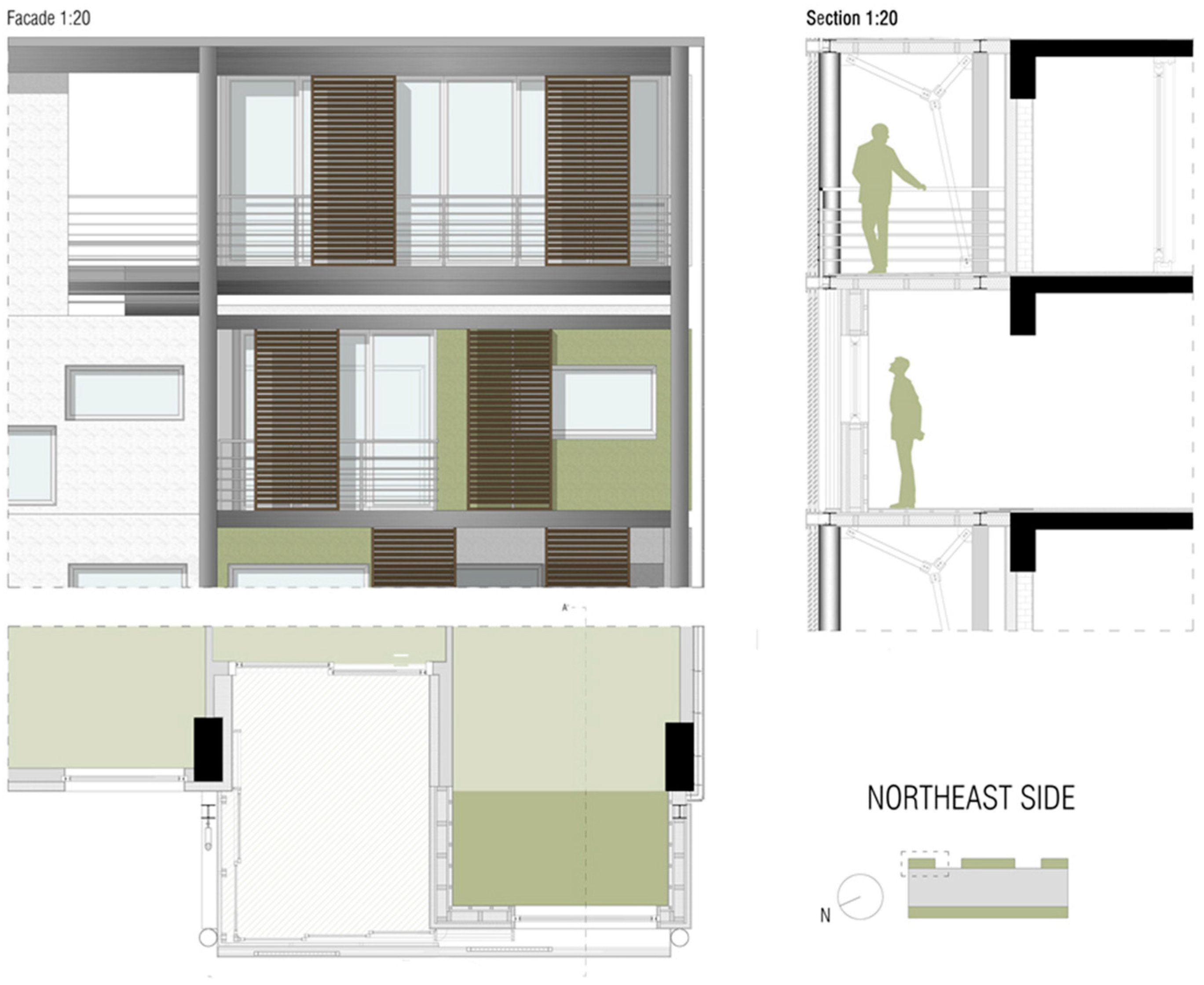
In terms of the architectural solutions, the development phase of the technical solutions for the realization of the horizontal and vertical partitions of the GET system is under process. Therefore, the Peristeri case application is the first approach to this detailed phase of design that will lead to the definition of the integrated technical solution.
Figure 17 shows drawings of another example of application.
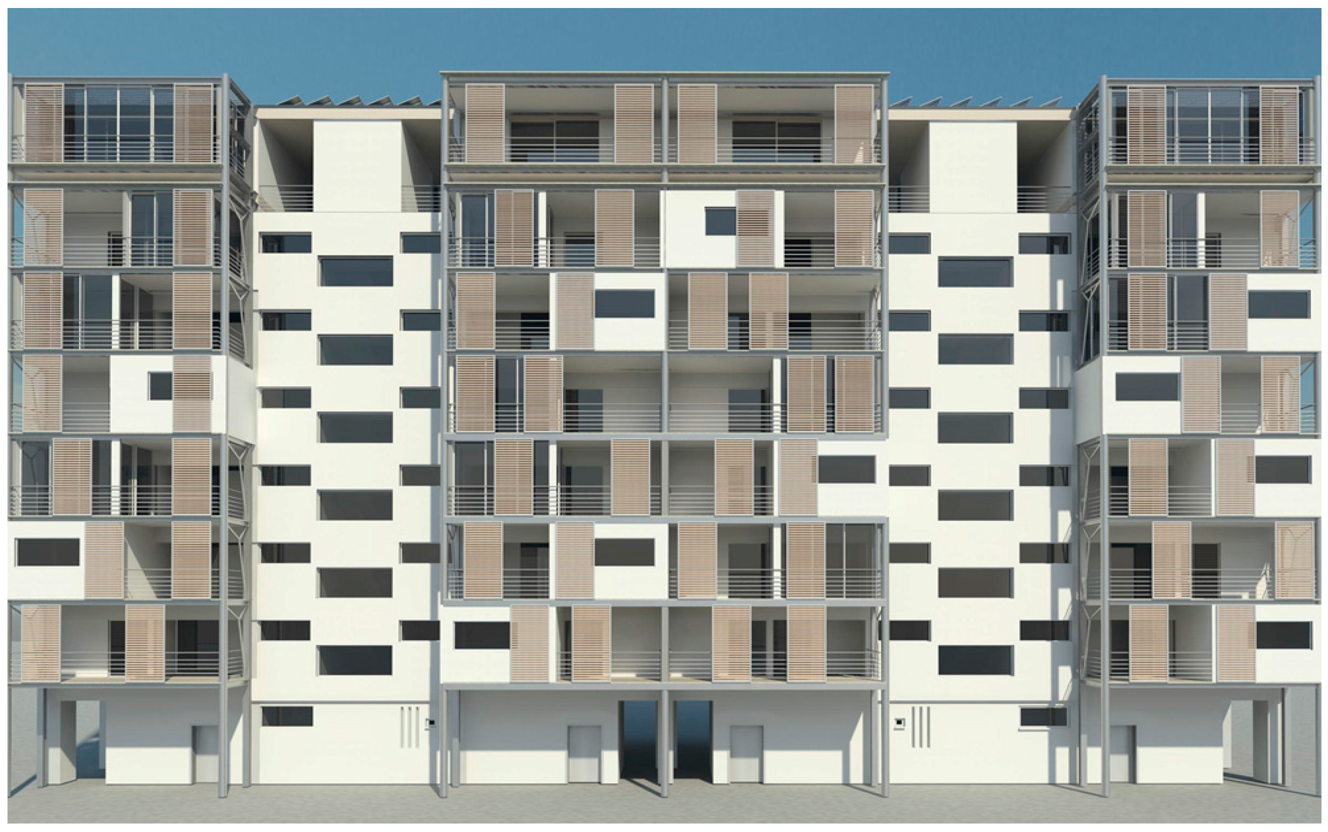
Different material, technical, and functional choices involve different compositional solutions. On the basis of the design hypotheses carried out on the Peristeri case, perspective views have been made of what may result following the realization of the Pro-GET-onE (
Figure 18).
Outstanding examples in architecture building practice so far that could be considered as the inspiration behind the GET strategy include the transformation of the Tour Bois Le Pretre by the French architect Frédéric Druot [
17,
18]. This is a significant example of deep renovation combining energy retrofit with architectural quality and social sustainability. Another significant example is the extension and refurbishment of the residential Tower Weberstrasse, Winterthur, an existing 12 level apartment tower, built at the 1960s by the architect H. Isler. The project refers to an extension of the rear facade planned by Bulkhalter Sumi architekten [
19].
In both examples, the additional space led to the variation of the existing apartments, the increase of a greater sense of security, and at the same time upgraded the social life of the community with the active participation of the owners during the whole procedure. New “envelopes” often consist of architectural spaces and units: the new volumes with the winter gardens, the extra balconies and galleries create a transition zone between the existing building envelope and the external climatic conditions and that results, as reported in the reference cases, in a consistent decrease in the initial energy consumption.
The architectural solutions here described, starting from a non-energy related objective like the increase of the rentable surface and, more generally, the increase of the asset value, prove that technological and architectural transformation in buildings do have the highest potential to decrease energy consumption in the existing ones. Regarding the case study of the Tower Weberstrasse [
19], the measured energy consumptions calculated on the heated surface before the renovation (3887 m
2) was calculated up to 604,244 kWh/year. This resulted in 155 kWh/m
2 per year in terms of gas consumption. After the renovation, the calculated energy consumption accounted for a global 61.5 kWh/m
2 per year, considering a total increased surface of 4.830 m
2, thus, including the addition.

 ,
, 


