Due to the low tensile capacity of concrete, RC structures are vulnerable to cracking. Fortunately, the high tensile strain capacity of ECC can compensate this defect of concrete, thus being an ideal retrofitting material. Some researchers have investigated the application of ECC strengthening in RC structures, including RC beams, columns, and beam–column joints. ECC is usually applied in combination with FRP textiles (
Figure 1) or steel bars in order to significantly increase the strength of the structure member. When ECC is introduced in a structure member, multiple tiny cracks form on the tensile surfaces or areas under complex stresses, such as the beam bottom soffit and joint core area, while the load bearing capacity of the structure member will not decrease. This multiple cracking process usually results in a ductile failure mode. FRP textiles and steel bars can also improve the structure integrity to some extent, especially in the strengthening of RC columns. However, the main role of FRP textiles or steel bars is to increase the strength of the structure members.
4.1. RC Beams Strengthened with ECC
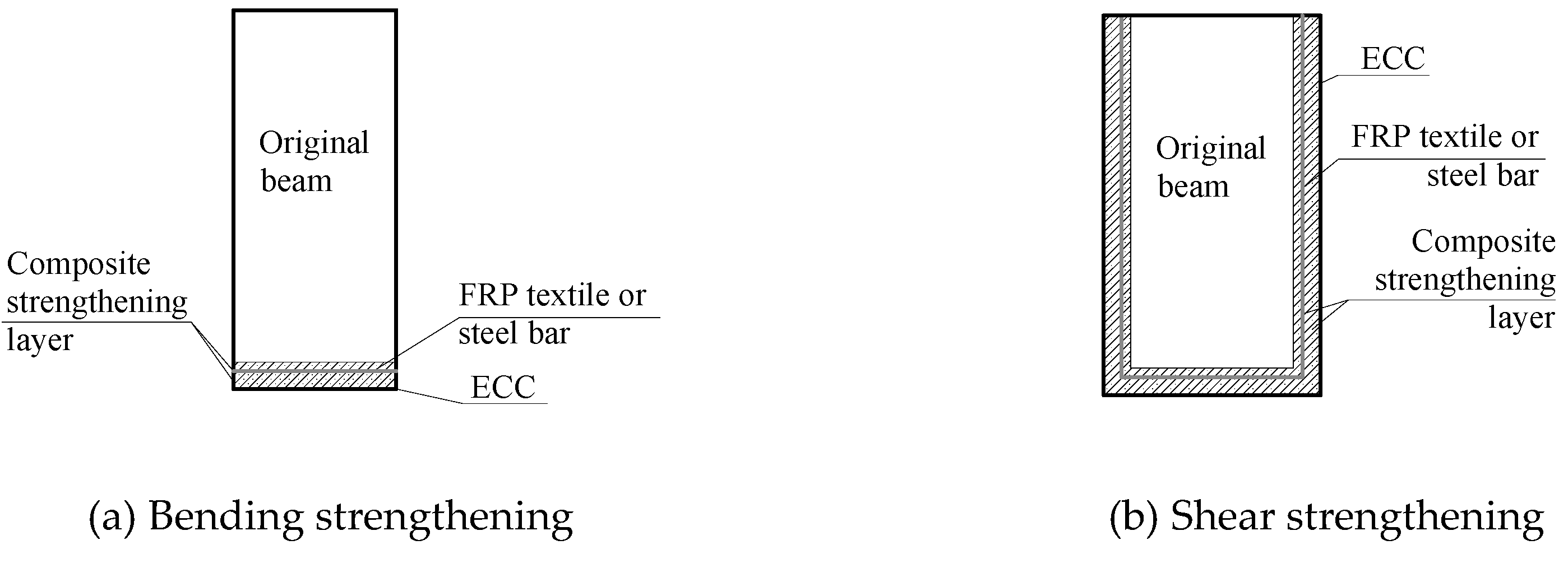
There are two strengthening arrangements for RC beams, i.e., the strengthening layer attached on the bottom soffit for bending strengthening (
Figure 2a) and U-shaped jackets used for shear strengthening (
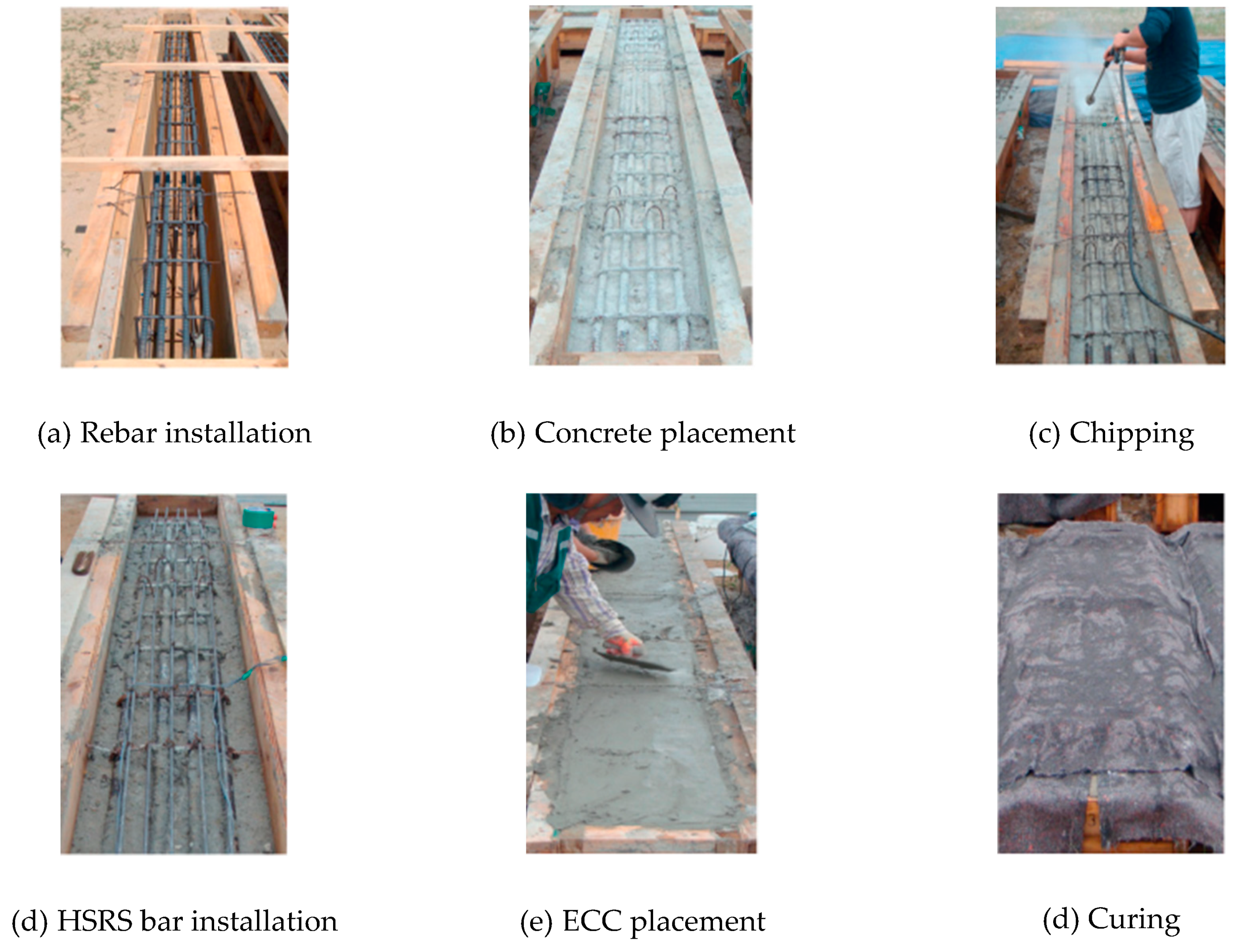
Figure 2b). The manufacturing process of beams strengthened with ECC and high strength reinforcing steel (HSRS) bars is shown in
Figure 3. For beams strengthened with ECC and FRP textile, the process is similar to those with ECC only, except that after a layer of ECC is plastered on the original concrete substrate, FRP bonding is conducted.
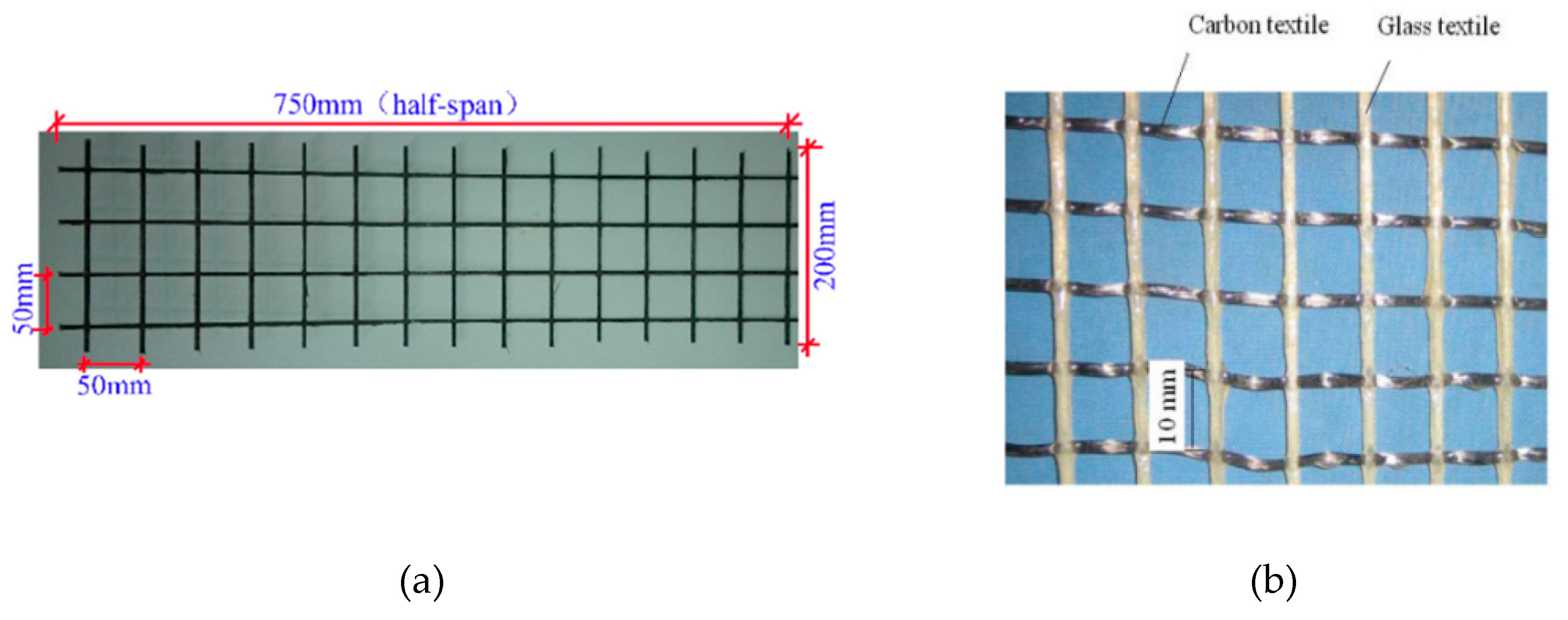
Zheng et al. [
60] combined ECC and a basalt FRP (BFRP) grid (
Figure 1a) to strengthen RC beams, which were externally attached on the beam bottom soffit and worked together as a composite reinforcement layer (CRL), as shown in
Figure 4. The test parameters were the grid thickness and the ratio of the CRL length to the clear span of the beam. The beams were subjected to four-point bending tests to investigate their flexural behavior. The strengthened beams, BB-1-500, BB-3-500, BB-3-450, and BB-3-400, failed in bending with BFRP rupture and concrete crushing, while the strengthened beam, BB-5-500, failed with partial debonding of the strengthening layer and BFRP rupture (
Figure 5a). Multiple fine cracks occurred in the composite reinforcement layer. However, for beams strengthened with BFRP only [
63], BFRP was completely debonded from the substrate concrete (
Figure 5b). Compared with beams strengthened with BFRP only, we can see the effective interface bonding of beams strengthened with ECC and BFRP, which can also be confirmed by analyzing the strain distribution along the beam depth, where the results showed no slip between the concrete and strengthening layer. The specimen details and strengthening effects of the beams are listed in
Table 2, where it is evident that the combination of ECC and BFRP grid strengthening greatly increased the strength and stiffness of the beams; however, the displacement was decreased.
Similarly, Dai et al. [
61] used textile reinforced ECC (TR-ECC) to strengthen RC beams. The textile used was carbon textile and glass textile (
Figure 1b), different from the BFRP grid in [
60]. In this paper, the beams were strengthened with an ECC strengthening layer attached on the bottom soffit except one (*ECC), whose ECC was attached on both the bottom soffit and the two vertical surfaces. The strengthening effect of ECC was also compared with that of steel fiber reinforced concrete (SFRC) and ordinary mortar. The test parameters included the textile stiffness, the matrix type, and the anchorage length of the textiles. Test results revealed that TR-ECC strengthening significantly increased the flexural capacity and stiffness of the beams. Beams strengthened with TR-ECC showed better performance than those with SFRC and mortar. Similar to [
60], debonding was not found before failure, indicating an effective bond between the strengthening layer and concrete substrate. Also, Yang et al. [
64] researched the flexural performance of RC beams strengthened with ECC and CFRP, which is proven as an effective strengthening scheme.
Kim et al. [
62] investigated the flexural behavior of RC beams retrofitted with strain-hardening cementitious composite (SHCC, i.e., ECC) and HSRS bars. The strengthening layer was attached on the bottom soffits of the beams, and then flexural bending tests were conducted. The test parameter was the number of HSRS bars. The test results revealed that ECC combined with HSRS bars can control the crack width as well as increase the stiffness and load bearing capacity of beams. Moreover, the stiffness and load bearing capacity increased with the number of HSRS bars.
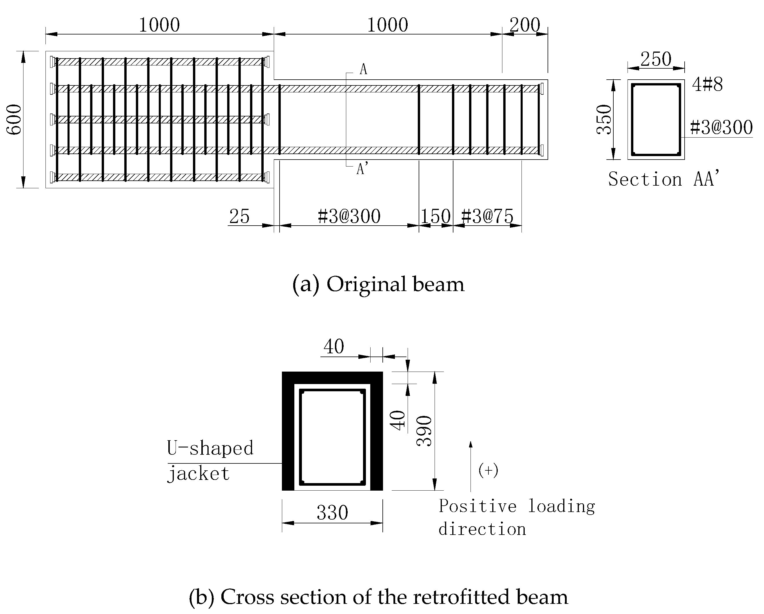
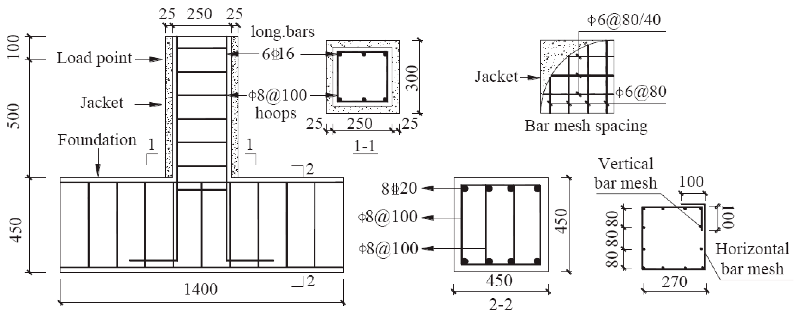
Huang and Chen [
65] manufactured six RC cantilever beams, five of which were shear strengthened with mortar jackets or ECC jackets, as shown in
Figure 6. The jackets were reinforced with or without steel meshes. The parameters were the matrix, layer of meshes, and category of meshes, as shown in
Table 3. All the beams were subjected to vertical cyclic loading. Experimental test results indicated that the ECC jacket was more effective than mortar jackets in restraining concrete spalling and crushing. Also, the combination of the ECC jacket and steel meshes was prone to the promotion of multiple tiny cracks and further enhancement of the shear performance of beams, including the shear strength capacity, deformability, and pinching behavior. In addition, the beam strengthened with the ECC jacket and a layer of steel mesh was the most effective retrofitting scheme.
Shang et al. [
66] investigated the shear behavior of fire damaged RC beams strengthened with steel reinforced ECC. Two types of ECC, including PVA-ECC and PE-ECC (polyethylene, PE), were used to retrofit the damaged beams. Test results showed that the strength, stiffness, and displacement increased a lot compared with the control beams, and the beams strengthened with PE-ECC showed better behavior.
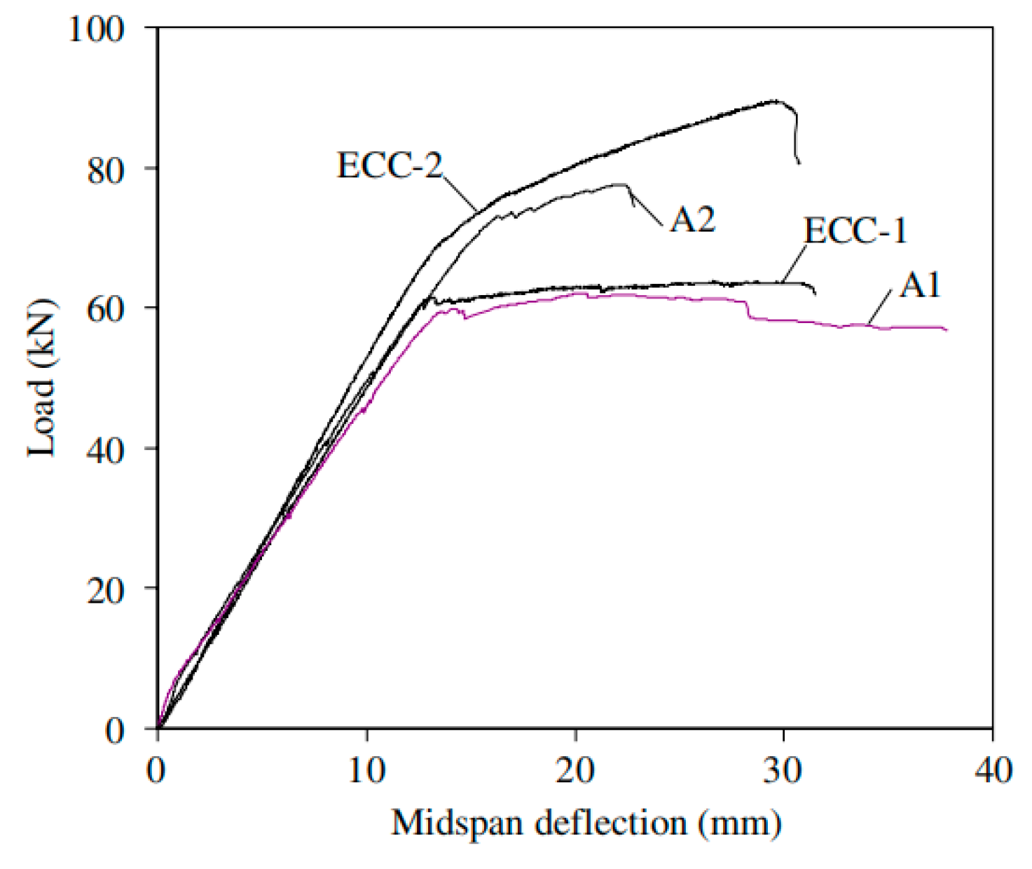
Maalej and Leong [
67] compared the behavior of RC beams strengthened with externally bonded FPR and FRP incorporating ECC, in which the concrete in the bottom region of the beams was replaced by ECC, as shown in
Figure 7. Beams A1 and A2 were the control beam and FRP bonded beam, respectively. Beam ECC-1 was strengthened by ECC only, and beam ECC-2 was strengthened by FRP incorporating ECC. It is obvious that FRP bonding significantly increased the bearing capacity. However, the deflection was decreased, owing to FRP debonding. When ECC was incorporated in ECC-2, the deflection capability increased considerably compared with A2 due to the tensile ductility of ECC materials but was still less than the control beam, A1. Finite element software, DIANA, was used to simulate the behavior of the beams, for instance, the FRP strains and load–deformation behavior. The simulation results agreed well with the experimental results. As shown in
Figure 8, the maximum CFRP stress in the strengthened beam with bonded FRP only was much higher than that with FRP incorporating ECC. Therefore, the load capacity of RC beams strengthened with the latter strategy was much higher. In addition, ECC delayed the CFRP debonding, thus increasing the effectiveness of the CFRP material. Meanwhile, ECC also reduced the loss of deflection capacity caused by FRP debonding or fracture.
Researchers also proposed a formula to predict the bearing capacity of the flexural strengthened beams. Based on the plane cross-section assumption and force equilibrium, flexural capacity formula were proposed according to different failure modes in [
64]:
where
xf is the depth of the equivalent rectangular compressive stress zone;
xbf,
xlfc, and
xuf are the depths of the compressive stress zone corresponding to different failure modes;
hf,
h0, and
are the distances from the centroids of CFRP, tensile steel bars, and compressive steel bars to the top of concrete compressive zone, respectively;
As (
),
σs (
), and
fy (
) are the cross-section area, the stress, and the yield strength of the tensile (or compressive) steel bars, respectively;
Af (
AE) and
ffu (
fe) are the cross-section area and the tensile strength of the FRP textile and ECC matrix, respectively;
α1 is a coefficient; and
fc is the compressive strength of concrete.
There is no formula for the shear strengthening of RC beams as yet, which needs further study.
4.2. RC Columns Strengthened with ECC
ECC combined with FRP textiles or steel bars was also applied in the strengthening of RC columns, including circular and square ones, or to change the section shape of the columns after strengthening, as shown in
Figure 9. In this strengthening scheme, the main role of the strengthening layer was to confine the core concrete, which was thus under a triaxial compression stress state. Therefore, the compressive strength and the ultimate compressive strain of the confined concrete increased. ECC can delay the formation and propagation of cracks and improve the brittle failure mode of concrete columns, thus increasing the energy absorption capability.
Four RC short columns were strengthened by Deng et al. [
68] with ECC jackets, while another was strengthened with a ferro-cement jacket for control. The retrofitting details are shown in
Figure 10. All specimens were subjected to lateral cyclic loading, which simulated seismic excitation. The effects of different design schemes on the performance of RC short columns were investigated. Test results showed that the failure modes of columns strengthened with ECC jackets were much more ductile than those of the control specimens, as shown in
Table 4. The shear strength and deformation capacity of the RC columns were effectively improved.
Zhu and Wang [
69] investigated the loading and deformation capacities of RC circular columns strengthened with FRP textile and ECC (
Figure 11). The specimens were subjected to a compressive test. The experimental results revealed that all strengthened RC columns failed by FRP rupture (
Table 5). The load and deformation capacity of confined RC columns increased with the reinforced FRP layer. Besides, the composite strengthened layer combined with FRP textile and ECC can provide effective lateral confining stress to the retrofitted RC columns and delay the yielding of the longitudinal bar.
AL-Gemeel and Zhuge [
70] investigated the strengthening effect of basalt fiber textile combined with ECC to confine RC columns. The effect of ordinary FRP strengthening decreased owing to the square shape of the column and brittleness of FRP, so that ductile ECC was incorporated and a circular mold was adopted to overcome these drawbacks. The cross section of the column changed from a square to circular shape. The strengthening details of the confined RC columns are shown in
Figure 12. The test parameters were the matrix type and basalt textile spacing, as shown in
Table 6. Compressive strength tests were conducted on all the columns. Test results showed that this strengthening scheme significantly increased the bearing capacity and ductility of RC columns.
Researchers also proposed several formulae to predict the shear capacity of the strengthened RC columns [
68]:
where
VC (
VL) and
h0 (
hl) are the shear contributions and the effective heights of the original RC column (the strengthening layer), respectively; 0.07
N is the shear contribution of the axial load to the shear strength;
λ is the shear span ratio of the columns;
ft and
ftl are the tensile strength of concrete and ECC, respectively;
fyv (
fyvl),
s (
sl), and
Asv (
Asvl) are the yield strength, the spacing, and the cross-section area of the stirrups (the FRP textiles or steel bars), respectively; and
αc and
αs are the effective strength coefficients of ECC and FRP textiles, respectively.
4.4. Fire Damaged RC Slabs Strengthened with ECC
Gao et al. [
72] and Hu et al. [
73] used BFRP reinforced ECC to strengthen fire damaged RC slabs. The strengthening procedure is shown in
Figure 14. The test parameters included the fire exposure time, matrix type, and layers of BFRP grids, as shown in
Table 7. This strengthening technique significantly increased the load-carrying capacity of RC slabs. Compared with polymer modified mortar, the ECC application resulted in a higher load capacity and ductility. However, the BFRP layer increased the load capacity but decreased the ductility at the same time. Most of the slabs failed in bending with the yielding of longitudinal bars, except slab B1-3, which failed in shear with plate end debonding of BFRP. This is because the BFRP debonding weakened the end section of the plate and led to shear failure.
Some researchers [
74,
75,
76,
77] also applied ECC materials to strengthen unreinforced masonry walls, which were constructed using bricks and mortars to resist horizontal loads, such as earthquakes. ECC strips or coatings, with or without the combination of steel mesh, were used to strengthen the unreinforced masonry walls and investigated the performance of the strengthened walls subjected to different loads, i.e., uniformly-distributed load, patch load, and low-velocity projectile impact. These efforts found that ECC retrofitting could significantly improve the lateral strength, ductility, and energy dissipation of unreinforced masonry walls.
Table 8 summarizes the strengthening materials and strengthening effects, from which we can see that for RC beams flexural-strengthened with ECC and FRP textiles, the strength and stiffness both increased; however, the deformation ductility decreased due to the brittleness of FRP textiles. Comparatively, beams strengthened with ECC and steel bars or steel meshes showed better behavior in ductility. The strengthening methods improved almost all the mechanical properties of RC columns, joints, and masonry structures.
ECC has been used in the real world. For example, it was used to retrofit the Ten-nou JR tunnel to prevent the concrete lining from cracking and spalling [
78]. The concrete dams of Hohenwarte II power plant were repaired with ECC to prevent the leakage of water [
79].


