In this section, the computational simulation of the annual operation of the investigated active cooling systems is analyzed and presented. The final goal is the estimation of the annual electricity consumption for the cooling of thermal zone 1 and the percentage of the heating load of thermal zone 2 (offices and shared spaces) that can be annually covered by the disposed heat recovery from the thermal zone 1 cooling process.
4.1. Operation Algorithm of the VAV System
The operation algorithm of the proposed VAV system in rough lines is:
The cooling load coverage of thermal zone 1 is the fundamental task of the whole system, with highest priority.
The heating load coverage of thermal zone 2 is accomplished in a second stage, by exploiting the available thermal energy disposed from the cooling process of thermal zone 1.
For the coverage of the thermal zone 1 cooling load, the following cooling sources are exploited with the particular order of priority:
- -
fresh air flow required for the ventilation of the thermal zone 2 indoor space
- -
recirculation air flow from the conditioned space of thermal zone 2, in the case of existing concurrent heating load
- -
additional fresh air flow from the ambient environment
- -
operation of the central heat pump unit.
The above roughly described operation algorithm is thoroughly analyzed below. The following process refers to each discrete calculation time step (one hour). In this operation algorithm presentation, the symbols presented in
Table 4 are used, all of them referring to the current time calculation step.
1. Case 1: Ambient temperature higher than indoor temperature
If the ambient temperature T
a is higher than the required indoor space temperature T
cm in thermal zone 1, a case exclusively expected during summer, then no physical cooling can be achieved. In this case, the total cooling load Q
cm of thermal zone 1 is exclusively covered by the available heat pump:
where q
hp is the final cooling power produced by the heat pump.
Obviously, in this case, with the ambient temperature higher than the required indoor space temperature in thermal zone 1 (30 °C), no heating load for thermal zone 2 is expected, hence, there is no sense to investigate the option of thermal power recovery for the indoor space heating.
2. Case 2: Ambient temperature lower than indoor temperature
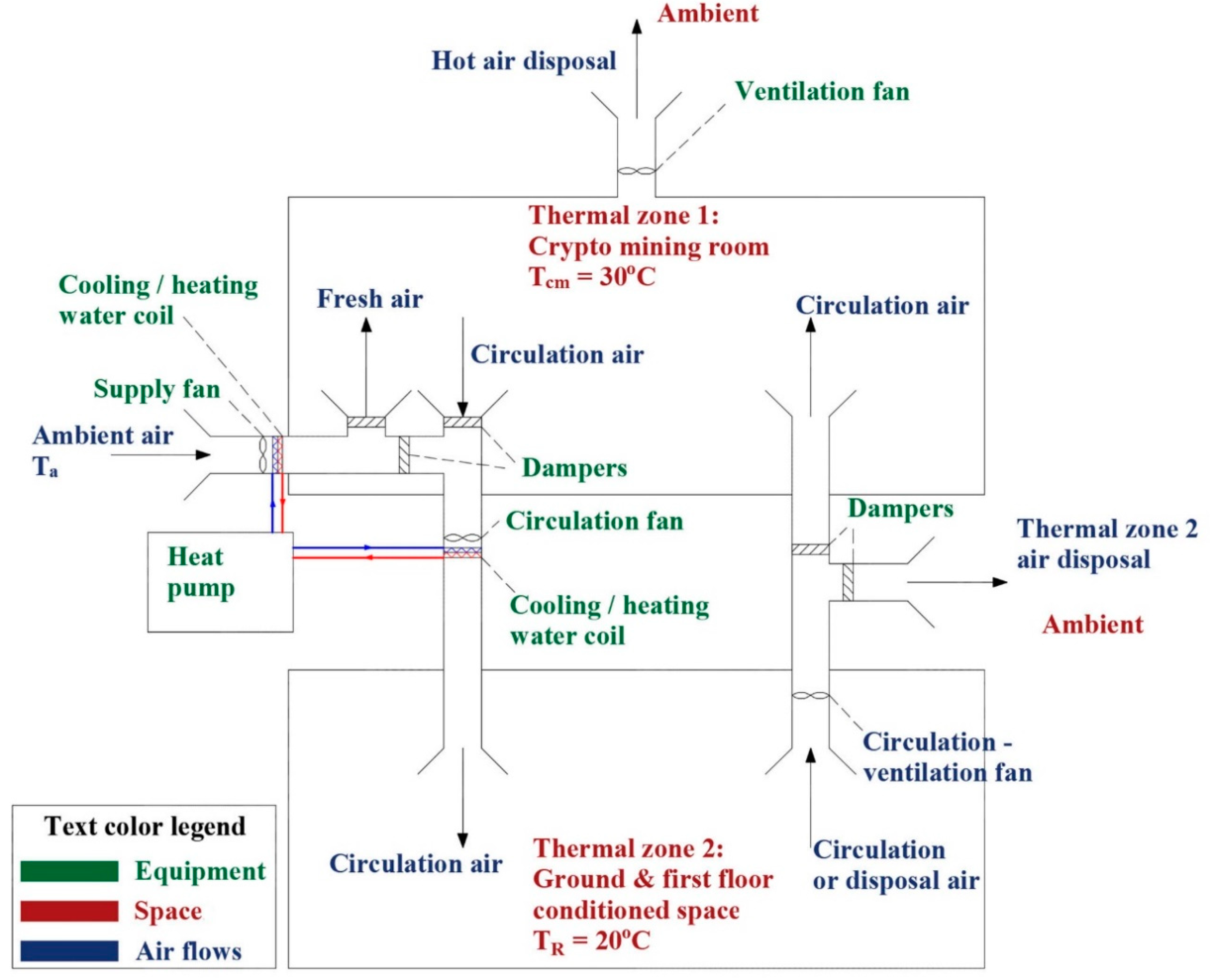
If the ambient temperature Ta is lower than the required indoor space temperature Tcm in thermal zone 1, a case met for most of the time during the annual period, then physical cooling can be implemented, by simply pumping fresh outdoor air into the conditioned space, without any mechanical cooling required from the heat pump. Physical cooling can be alternatively achieved by recirculating air between thermal zone 2 (TR = 20 °C) and thermal zone 1 (Tcm = 30 °C). The latter can be combined with the heating load coverage of thermal zone 2 during winter.
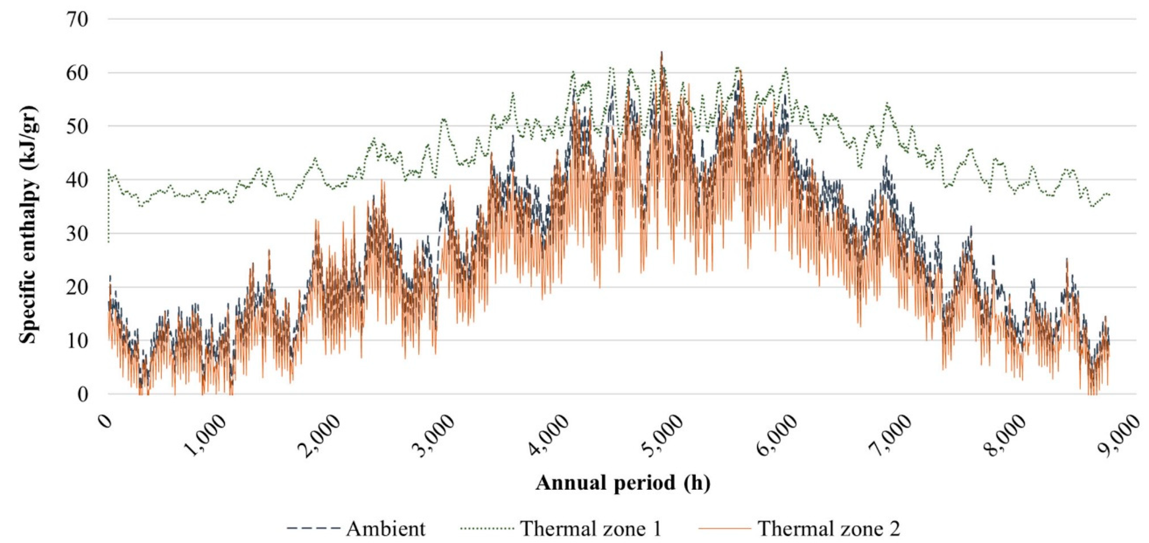
In this current case (Ta < Tcm), a number of sub-cases must be investigated. The main concept is to exploit the fresh air flow required for the ventilation of the thermal zone 2 indoor space to cool down thermal zone 1. Hence, fresh air of the low ambient temperate Ta is pumped into thermal zone 1 to remove the produced thermal power and keep the indoor space temperature at the required value of Tcm = 30 °C.
If q
v is the cooling power that corresponds to this fresh air flow, this power is given by the relationship:
where
is the required air mass flow rate for the ventilation of the thermal zone 2 indoor space and Δh
a is the specific enthalpies difference between the thermal zone 1 space h
cm and the ambient air h
a. If Q
cm is the cooling load of thermal zone 1 at the current calculation time step, two sub-cases are distinguished:
• Case 2.1: qv > Qcm
If the cooling power q
v of the fresh ventilation air flow is higher than the cooling load Q
cm of thermal zone 1, then the cooling load Q
cm can be totally covered by the fresh air flow. In order not to overcool down the conditioned space, the mass flow rate
required for the cooling process will be:
The cooling power coverage from the fresh air flow q
vcm will be equal to the total load:
Obviously, the required cooling power production q
hp from the heat pump will be null:
In the case of any existing concurrent heating load Q
R for thermal zone 2, the disposed heat from the cooling space can be exploited to cover a part or all of it. The thermal power q
r that can be recovered for the heating of thermal zone 2 is given by the relationship:
where Δh
R is the specific enthalpies difference between thermal zones 1 h
cm and 2 h
R. Two sub-cases are distinguished:
- Case 2.1.1: QR ≤ qr
If the heating load Q
R of thermal zone 2 is lower than the recovered heat q
r from the cooling process of thermal zone 1, then all or a part of the heating load can be covered from the heat recovery q
r, depending on the required mass flow rate
which must be recirculated between these two thermal zones. Specifically, in order to cover all the heating load of thermal zone 2, the required mass flow rate should be:
If is the maximum mass flow rate that the fan can provide, then:
▪ Case 2.1.1.a: :
All the heating load Q
R can be covered by the disposed heat from the cooling process:
The remaining heating demand Q
RD for thermal zone 2 will be null:
The recovered heat surplus:
from thermal zone 1 is disposed in the ambient.
The mass flow rate from the circulation fan will be .
▪ Case 2.1.1.b: :
Only a part of the heating load can be covered by the disposed heat from the cooling process:
The remaining heating demand Q
RD for thermal zone 2 will be:
The recovered heat surplus will be null:
The mass flow rate from the circulation fan will be .
- Case 2.1.2: QR > qr
If the heating load Q
R of thermal zone 2 is higher than the recovered heat q
r from the cooling process of thermal zone 1, then all the recovered thermal power can be used for the heating load coverage. The capability of the available fan to provide the required air mass flow rate must be checked again, similarly with the previous sub-section. In order to transfer all the recovered heat to thermal zone 2, the required air mass flow rate must be:
If is the maximum mass flow rate that the fan can provide, then:
▪ Case 2.1.2.a: :
All the recovered heat q
R can be provided for the coverage of the corresponding heating load of thermal zone 2:
The remaining heating demand Q
RD for thermal zone 2 will be:
The recovered heat surplus will be zero:
The mass flow rate from the circulation fan will be .
▪ Case 2.1.2.b: :
Only a part of the recovered heat can be provided for the thermal zone 2 heating load coverage:
The remaining heating demand Q
RD for thermal zone 2 will be:
The recovered heat surplus:
from thermal zone 1 is disposed in the ambient.
The mass flow rate from the circulation fan will be .
• Case 2.2: qv ≤ Qcm
If the cooling power q
v of the fresh air mass flow rate
is lower than the cooling load Q
cm of thermal zone 1, then all the available cooling power of the fresh air flow is utilized to cover only a part of the cooling load. The cooling power coverage from the fresh air flow q
vcm will be equal to the total available cooling power of the flow:
The thermal power q
r that can be recovered for the thermal zone 2 heating is given by the relationship:
The remaining cooling load of thermal zone 1 is:
This remaining cooling load is preferable to be covered by disposing the removed thermal power to cover the heating load Q
R of the thermal zone 2 space, if there is any. To this end, an air mass flow rate
should be recirculated between the thermal zone 1 (T
cm = 30 °C) to the thermal zone 2 spaces (T
R = 20 °C), calculated as presented below:
where, as previously, Δh
R is the specific enthalpies differences between the thermal zones 1 and 2. If
is the maximum mass flow rate that the fan can provide, then the following sub-cases are distinguished:
- Case 2.2.1: :
In this case the available fan is capable to provide the required air mass flow rate for the removal of the remaining cooling load from thermal zone 1. Yet, it must be further investigated if there is the requirement for the coverage of the corresponding heating load. For this reason two more sub-cases are examined:
▪ Case 2.2.1.a: QR ≥ Qcm − qv:
In this case, the heating load of thermal zone 2 is higher than the remaining cooling load of thermal zone 1. Hence, all the remaining cooling load in thermal zone 1 can be covered from the heating of thermal zone 2. This means that an air mass flow rate
will be recirculated from thermal zone 2 (at temperature T
R = 20 °C) to thermal zone 1, cooling the latter and, while returning back at the temperature of 30 °C, heating thermal zone 2. The cooling load coverage q
Rc from the heating load of thermal zone 2 will be:
Obviously, the required cooling power production q
hp from the heat pump will be null:
For the heating load coverage calculation of thermal zone 2, there is a remaining load to be covered equal to:
This remaining heating load is compared with the recovered thermal power qr from the fresh air flow:
A. If qr ≥ QR − qRc:
Then all the remaining heating load can be potentially covered by the recovered heat with the fresh air flow. To this end, an additional air mass flow rate will be needed, equal to:
The ability of the available fan to transfer this additional air mass flow rate is checked:
A.1. If :
Then the fan is able to transfer the additionally required air mass flow rate, so all the heating load in thermal zone 2 will be covered by the disposed heat from thermal zone 1 cooling with fresh air. The remaining heating load will be null:
The total mass flow rate from the fresh air fan will be:
A.2. If :
Then the fan is not able to transfer the entire additionally required air mass flow rate, so only a part of the heating load in thermal zone 2 will be covered by the disposed heat from thermal zone 1 cooling with fresh air:
The remaining heating load will be:
The total mass flow rate from the fresh air fan will be:
B. If qr < QR − qR:
Then the coverage of the heating load can be potentially equal to the recovered heat, while there will be a remaining heating load Q
RD to be covered. Again, the capability of the fan to provide the additional required air mass flow rate must be checked. The required air mass flow rate to exploit all the recovered heat q
r for the thermal zone 2 heating is:
B.1. If :
Then the fan is able to transfer the additionally required air mass flow rate, so all the recovered heat qr can be exploited for the thermal zone 2 heating.
The remaining heating load will be null:
The total mass flow rate from the fresh air fan will be:
B.2. If :
Then the fan is not able to transfer the additionally required air mass flow rate to exploit all the recovered heat. Only a part of the recovered heat can be transferred to thermal zone 2:
The remaining heating load will be:
The total mass flow rate from the fresh air fan will be:
▪ Case 2.2.1.b: QR < Qcm − qv:
In this case, the heating load of thermal zone 2 is lower than the remaining cooling load of thermal zone 1. Only a part of the remaining cooling load in thermal zone 1 can be covered from the heating process of thermal zone 2, which will be equal to:
The remaining cooling load:
can be potentially covered by increasing the mass flow rate of the fresh air flow, more than the required value for the indoor space ventilation. To this end, an additional fresh air mass flow rate
will be required, equal to:
A total mass flow rate of fresh air is now required, equal to .
If is the maximum fan’s mass flow rate from the ambient environment, then:
If
Then the remaining cooling load is fully covered with the increase of the fresh air flow:
The cooling power production from the heat pump is null:
If
Then the maximum additional mass flow rate from the ambient environment can be:
and the additional cooling load coverage of thermal zone 1 will be:
The cooling power production from the heat pump will be:
Obviously, in this sub-case (
QR < Qcm − qv), the heating load of thermal zone 2 is fully covered by the recovered heat for the cooling of thermal zone 1. There is no remaining heating load:
- Case 2.2.2: :
In this case the available fan is not capable of providing the required air mass flow rate for the removal of the remaining cooling load from thermal zone 1. The maximum cooling load q
Rmax that can be removed from the cooling space and be exploited for the concurrent heating of thermal zone 2 is:
As in the previous sub-case, the requirement for the heating load coverage for thermal zone 2 should be checked. Two further sub-cases are distinguished:
▪ Case 2.2.2.a: QR ≥ qRmax:
In this case, the heating load of thermal zone 2 is higher than the maximum load which can be covered by the recovered heat. This means that the cooling load coverage q
Rc from the heating load of thermal zone 2 will be:
Since the maximum air mass flow rate has been reached, the coverage of the thermal zone 2 heating load will be equal to q
Rc. The remaining heating load will be:
▪ Case 2.2.2.b: QR < qRmax:
In this case the heating load of thermal zone 2 is lower than the maximum load which can be covered by the recovered heat. Only a part of the remaining cooling load in thermal zone 1 can be covered by the heating of thermal zone 2, which will be equal to:
The required mass flow rate will be:
All the heating load of thermal zone 2 will be covered:
The remaining cooling load of thermal zone 1 for both the above sub-cases will be:
As in the previous case, this remaining cooling load can be potentially covered by increasing the mass flow rate of the fresh air flow, more than the required value for the indoor space ventilation. To this end, an additional fresh air mass flow rate
will be required, equal to:
A total mass flow rate of fresh air is now required, equal to .
If is the maximum fan’s mass flow rate from the ambient environment, then:
If
Then the remaining cooling load is fully covered with the increase of the fresh air flow:
The cooling power production from the heat pump is null:
If
Then the maximum additional mass flow rate from the ambient environment can be:
and the additional cooling load coverage of thermal zone 1 will be:
The cooling power production from the heat pump will be:
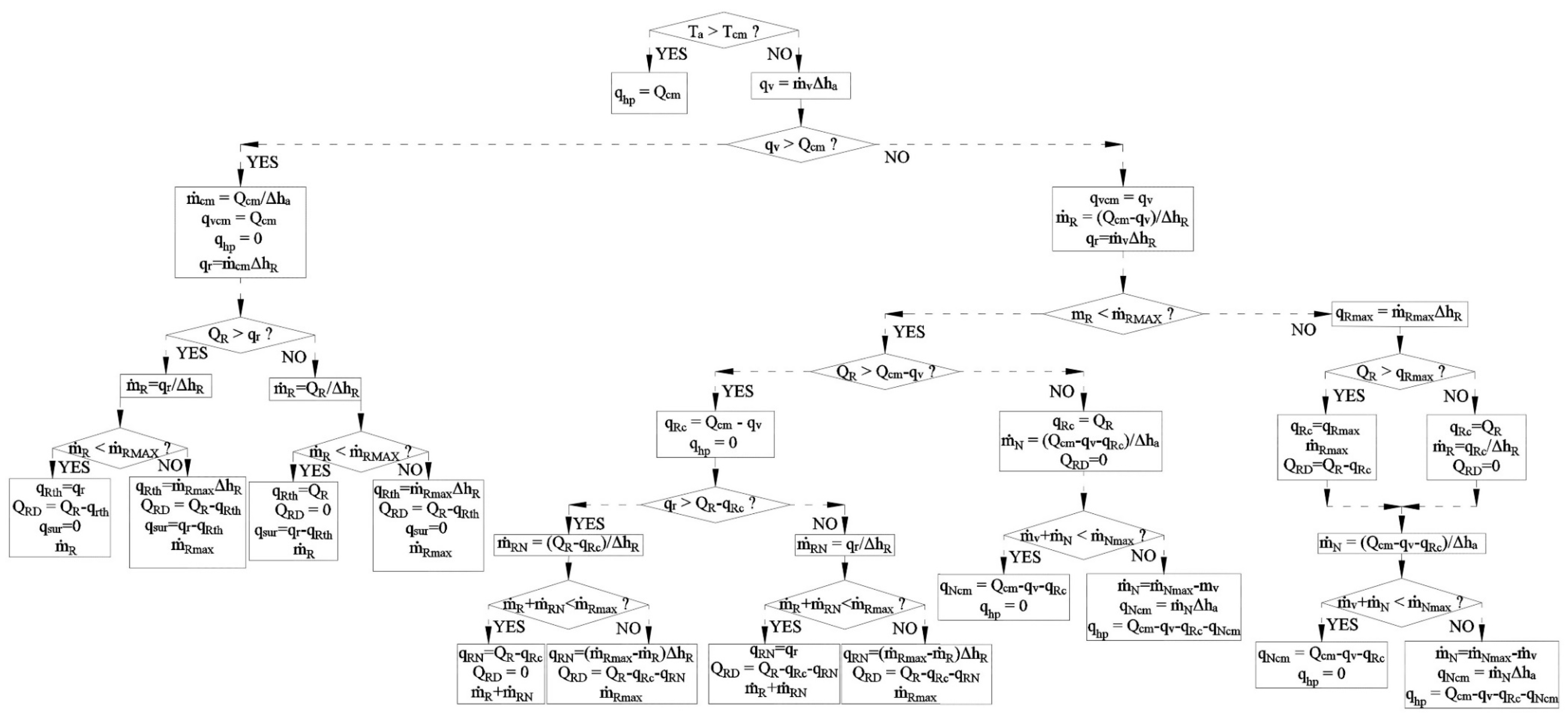
The above operation algorithm is graphically depicted in
Figure 6.
It must be underlined that with the structure of the proposed operation algorithm, it is intended to maximize the coverage of both the cooling load of thermal zone 1 and the heating load of thermal zone 2 with physical cooling and heat recovery, respectively. Specifically, as it is revealed with the presentation of the operation algorithm, first of all, the cooling load coverage of thermal zone 1 is examined through the fresh air flow for the ventilation requirements of thermal zone 2. The ventilation of the indoor space is obligatory, according to the relevant directives, hence, given the fact that this fresh air flow exists permanently, the first task is to exploit the corresponding cooling power from this flow, of course if Ta < Tcm.
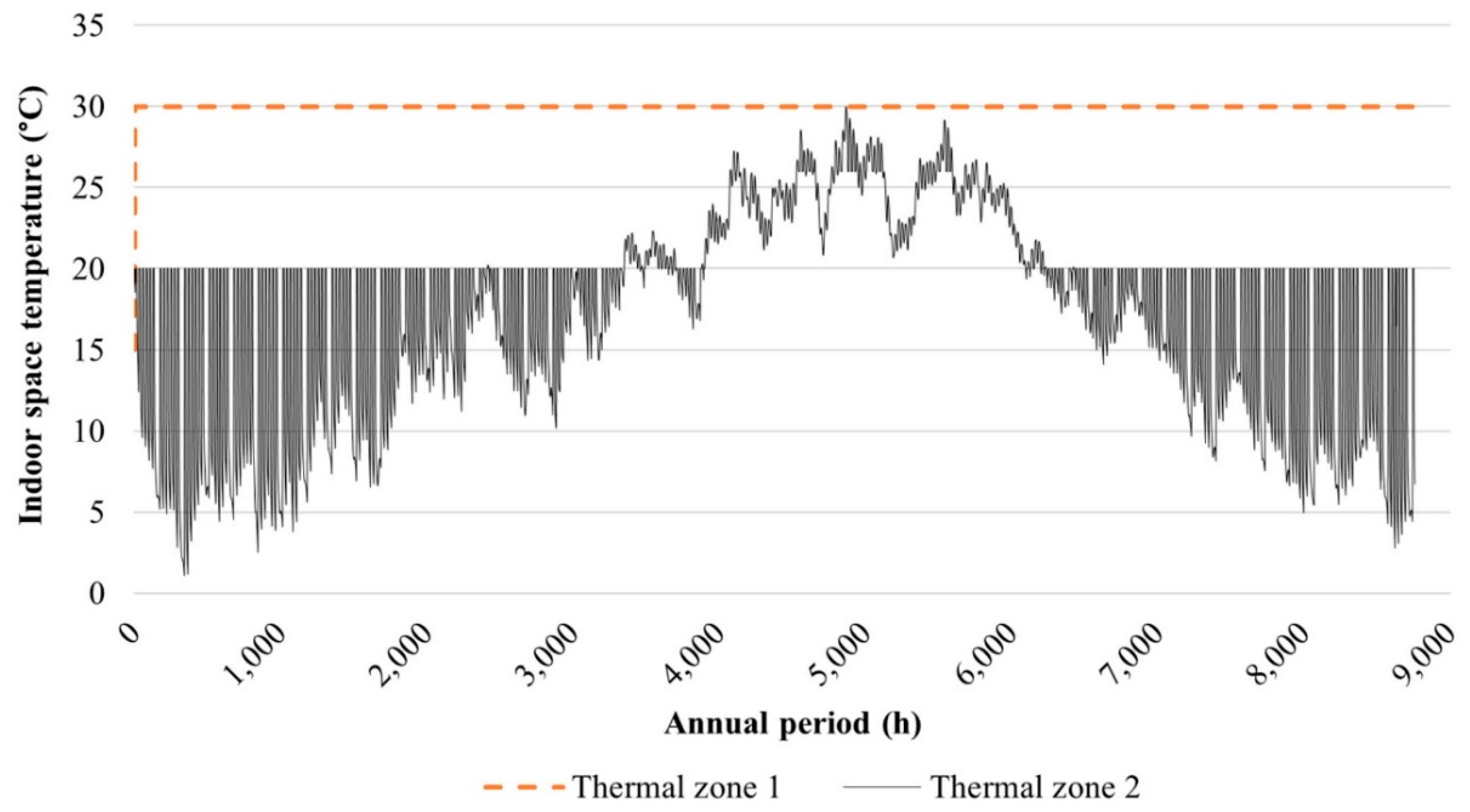
Secondly, in case the cooling load is not fully covered in the first step, instead of increasing the fresh air flow, the exploitation of any existing heating load in thermal zone 2 for the coverage of the remaining cooling load is examined. The indoor space temperature in thermal zone 2 is set at 20 °C, while the required temperature in thermal zone 1 is 30 °C. Hence, by circulating air between thermal zones 1 and 2, the first is cooled down and the second is heated. This is the task with the second in order priority towards the full coverage of the cooling load in thermal zone 1.
Thirdly, additional fresh air flow is provided, up to the available fan’s maximum flow rate and beyond the ventilation requirements for thermal zone 2, for the coverage of any remaining cooling load in thermal zone 1. Finally, in the case of the cooling load still remaining uncovered in thermal zone 1, the heat pump is put on duty, as the ultimate alternative for cooling power production.
The above essential targets are fulfilled with the proposed operation algorithm. It is certain that with this approach, the contribution of physical cooling and heat recovery, namely without the intervention of the heat pump, is maximized, while the utilization of the latter is limited. The above are clearly depicted in the results from the execution of the computational simulation procedure.


