Abstract
In maintaining the efficiency of coal mining, the stability of roadway plays a significant role, as it is closely related to the production of coal and the safety of personnel. In deep underground coal mines, the rheological deformation of roadway normally occurs, which affects its service life. To address this problem, in this paper, a novel high-efficiency Jet Grouting (JG) technique was presented, and its control effect on roadway stability was investigated. A creep test of a coal specimen in a laboratory scale was performed, and its creep behavior was revealed. The rheology of the coal mass surrounding the roadway was further analyzed according to the field-monitoring results of roadway deformation. A time-dependent numerical model with a Burger-creep visco-plastic model (CVISC) was established and validated by comparing the calculated displacement with in-situ measurement. The JG technique was tested in the field, and its applicability and practicability were confirmed. According to the validated model and field test results of JG, a numerical model with CVISC by JG support was established to analyze the effect of JG on the roadway. The results showed that the JG support can effectively reduce roadway deformation, optimize stress conditions, and reduce the extent of the plastic zone around the roadway. The rheological properties of the soft coal roadway were constrained and long-term stability was ensured. This pioneering work can guide the application of JG for the stability control of roadways and promote the sustainability of coal mining efficiently.
1. Introduction
The efficiency and sustainability of coal mining are greatly affected by the stability of the roadway (a transportation corridor) in underground mines [1]. Ensuring the long-term stability of the roadway is a quite challenging task in deep coal mines, although recent advances in support systems have been presented and utilized [2,3,4,5]. Experience and engineering practice have proven that roadway stability is closely related to the time-dependent behavior of the surrounding rock mass [6,7,8]. Normally, the time-dependent deformation of the rock mass is called rheology. When driving a roadway in poor geological conditions, such as weak rock mass and soft coal mass, the rheological deformation of the roadway is more serious. To maintain roadway stability, some traditional support techniques such as a bolting system, shotcrete, and steel sets have been utilized in some cases [9,10,11,12,13]. However, most support systems fail over time because of the rheological displacement of the surrounding rock mass. Therefore, further reinforcement and maintenance are necessary, which affects the service of the roadway and incurs high costs.
Many laboratory and field tests have confirmed that rock with high strength and integrity exhibits lower rheological properties [14,15,16,17,18]. In accordance with this, the grouting technique as a reinforcement method was applied to improve the physical and mechanical properties of the rock mass. After grouting treatment, the strength parameters of the rock mass, such as the cohesion and friction angle, increased considerably, and therefore its ability to resist rheology was enhanced [19,20]. However, for the roadway in a soft coal mass, it is difficult to utilize conventional grouting techniques, as the groutability and diffusion radius of the soft coal mass are severely limited [21].
To address this issue, a pre-grouting method—namely Jet Grouting (JG)—was introduced to reinforce the coal mass. The JG technique was invented for foundation treatment and it has been used for tunnel construction by improving soil strength before tunneling [22,23,24,25]. In practice, high-pressure cement grout is injected into a soft coal mass and mixed with coal particles cut by a high-velocity jet, and, therefore, a “coalcrete” composite with high strength is generated. By this technique, the properties of the original soft coal mass are deeply changed, and the formed coalcrete can be further used to construct coalcrete columns around the roadway profile. After roadway excavation, some additional support materials, such as shotcrete and U-shaped steel sets, can be applied and combined with preformed coalcrete columns, and, consequently, a JG support system is generated [26]. As this is a relatively new technique in coal mines, reports about the application of JG on the support system are limited. In addition, the control effect of JG on roadway stability has not been revealed. As described above, the rheological properties of the soft coal mass had a negative effect on roadway stability, and, thus, it is necessary to evaluate the support of JG in controlling the time-dependent behavior of the soft coal mass surrounding the roadway.
In this study, the rheological properties of a typical coal roadway were revealed, and the mechanism of the control effect of using JG support on roadway stability was investigated. A creep test of a coal specimen was conducted to analyze the creep behavior. Then, based on the field measurement, the rheological behavior of the roadway was obtained. A time-dependent numerical model was established and validated by comparing the roadway displacement from the calculation with field monitoring results. Furthermore, according to the field tests of JG and the validated model, a model with JG support was established, by which the control effect of JG on roadway stability was revealed. The mechanism of JG in controlling the development of deformation, stress conditions and the plastic zone around the roadway was systematically analyzed. The results are very encouraging and can guide the application of JG in coal mines.
2. Time-Dependent Behavior of a Soft Coal Roadway
2.1. The Geological Setting
A typical soft coal roadway is located at Guobei coal mine, in Huaibei coalfield in the east of China. The buried depth of this roadway is around 700–750 m. A conventional retreat Longwall Top Coal Caving method (LTCC) was utilized. A designed support system (i.e., rock bolts, U-shaped steel set, and shotcrete) was applied to such a roadway (see Figure 1a). The coal—with a thickness of around 10 m—is extremely soft, and collapse and spalling normally occur when tunneling a roadway (Figure 1b). The immediate and main floors are 2.0 m thick mudstone and 15 m thick sandstone, respectively. The immediate roof with mudstone is 2.7 m in thickness, and the main roof with sandstone is 23 m in thickness. A field test of such soft coal is shown in Figure 1c,d; an intact coal sample can be easily crumbled just by hand. The fractures and cracks were full in the coal mass, because of the frequent tectonic movement of coal layers in this coalfield historically. Such soft coal mass easily experiences rheology. The poor geological conditions normally cause the failure of the original support system, and, therefore, a larger deformation of the roadway occurs.
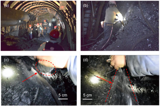
Figure 1.
The geological setting of the studied roadway: (a) the original support system; (b) the collapse and spalling in soft coal mass; (c) a soft coal sample in hand; (d) the coal sample in fragmentized coal particles.
2.2. Creep Behavior of Soft Coal Specimen
As described above, the rheological soft coal mass had a negative effect on the roadway stability. Thus, a uniaxial creep test with multi-stage loading was performed on a soft coal specimen to evaluate its time-dependent property. A constant loading (σ1) was applied on the specimen and maintained for a certain time (t1); then, the loading was increased to σ2 and kept CONSTANT from t1 to t2. Then, the mentioned procedures were repeated several times until specimen failure. The sketch maps of the loading and strain–time curve are shown in Figure 2. The creep results of the coal specimen are shown in Figure 3. It is clear that the soft coal specimen under various loadings displayed time-dependent strains during the creep stages of the tests. The specimen began to creep under a small stress condition (0.25 MPa). Normally, with lower stresses, the creep of the coal sample exhibits a two-stage creep behavior (stage A, decelerating creep, and stage B, uniform creep behavior), as shown in Figure 3b. With an increase in stress, sometimes the specimen directly fails during its loading process (the last loading is shown in Figure 3a). Overall, it has been indicated that the time-dependent behavior of soft coal cannot be ignored.
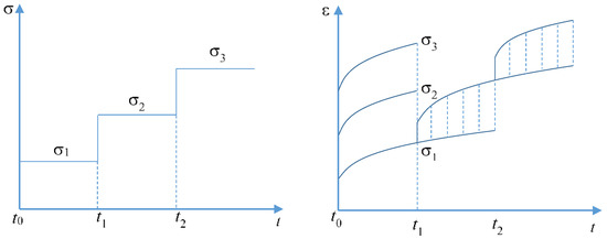
Figure 2.
Diagrammatic sketch of loading on uniaxial creep test and the data processing of the strain–time curve.
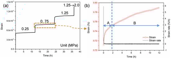
Figure 3.
Uniaxial creep test results under different stresses, showing the changes of axial strain versus time: (a) full creep curve under various stress; (b) creep curve under stress of 0.75 MPa.
2.3. Field Observation of Roadway Deformation
The field measurements of the roadway deformation were obtained (shown in Figure 4). As can be seen, the roof-to-floor displacement and sidewall convergence demonstrated time-dependent features. With the increase in time, the displacement of the roof and sidewalls evidently increased. The maximum convergence of the sidewalls and roof-to-floor displacement reached 880 mm and 310 mm, respectively. In 300 days, this roadway experienced re-excavation and reinforcement several times, which meant the rheology of the soft coal mass affected the roadway stability severely.
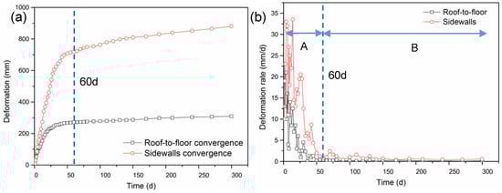
Figure 4.
Measured convergence and deformation rate of roadway: (a) convergence; (b) deformation rate.
Then, the deformation rate of the roadway was calculated by the monitoring data (shown in Figure 4b). Similar to the creep behavior of a coal specimen, there were also two rheology stages (Stages A and B) of the roadway. Stage A showed that the displacement rate decreased quickly, in around 60 days, and the maximum values of the sidewall convergence rate and roof-to-floor convergence rate were 33.5 mm/day and 23 mm/day, respectively, showing a decelerating rheological characteristic. The deformation rate in Stage B was small but still larger than zero, signifying the rheological deformation increased gradually.
3. Time-Dependent Numerical Modeling and its Validation
3.1. The Numerical Model of the Roadway by Conventional Support
A FLAC 3D (fine difference code) numerical model was established to simulate the deformation properties of soft coal roadway (Figure 5a). The size of the roadway, the lithology of strata, and their corresponding thickness were consistent with the real situation. To minimize the boundary effects, a domain 60 × 60 m was selected at XZ direction, which was about ten times the span of the roadway section. In the YZ direction, the length was set as 100 m and the studied cross-section was chosen in the middle of the roadway. The element size and aspect ratios were refined near the roadway and gradually increased outwards. The support structures, such as rock bolts and shotcrete, were generated in the model by cable and shell structural elements, respectively. The U-shaped steel sets were simulated by shell element by converting their supporting effect to equivalent elastic modules of the shell. The properties of the support materials are given in Table 1. Some monitoring points were set on the roof, floor, and sidewalls of the roadway to obtain the displacement (shown in Figure 5b). The vertical stress and horizontal stresses applied to the model were taken from the literature about this coal mine [27].
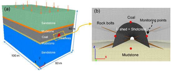
Figure 5.
Numerical model for conventional support: (a) the established 3D model; (b) the details of the roadway section in the model.

Table 1.
The support materials used in the numerical simulation.
3.2. Burger–Creep Viscoplastic Model (CVISC)
One of the objectives of this study is to reveal the rheological behavior of the soft coal mass around the roadway. To simulate the time-dependent behavior of the soft coal mass, the Burger–creep viscoplastic model (CVISC) was adopted to model the coal mass, which was effective at reflecting the rheological properties of the rock or coal mass, and was confirmed in the literature [3,7,14,15]. In CVISC, the rheological parameters ηM, GM, ηK and GK represent the time-dependent behavior of the unit element corresponding to a Burgers model (visco-elastic constitutive law), while C, φ, and E denote the elastic–plastic behavior of the unit element, corresponding to a Mohr–Coulomb (M–C) model [28]. A back-analysis method was referenced to obtain the rheological parameters of the coal mass [29]. The results are given in Table 2.
Table 2.
Back analysis results of rheological parameters of the soft coal mass.
3.3. Properties of the Rock Mass
Based on the field measurement, the time-dependent behavior of the rock mass was not obvious compared with the coal mass, and, consequently, the M–C model was used in the surrounding rock. According to the engineering geological investigation, the rock mass rating (RMR) was inferred from underground mapping, and then the rock mass quality was determined by the geological strength index (GSI). Then, the rock mass properties were calculated based on the following equations (Equation (2) to Equation (12)) in the literature [30,31,32]. The results were summarized in Table 3.
where GSI means the value of the geological strength index, and RMR is the value of rock mass rating classification.
Table 3.
Rock mass properties.
The general form of Hoek–Brown criterion is given as:
where mb, s and a are the rock mass constants; the following equations can be used for the calculation of the constants:
By setting the σ3 to zero, the uniaxial compressive strength of rock mass (σcm) is calculated. Similarly, the tensile strength (σt) of rock mass is calculated by setting σ1 = σ3 = σt.
The global rock mass strength is more useful when the estimation of overall strength is required without detailed knowledge of the failure propagation process, as in the considered case in this study. The global rock mass strength is calculated as follows:
In order to calculate the rock mass deformation modulus, two GSI based empirical equations are widely used:
In this study, D, the disturbance factor, is assumed as zero. It is also possible to obtain the equivalent cohesion (c) and friction angle (ϕ) of the rock mass for the design tools based on Mohr–Coulomb failure criterion:
where σ3n = σ3max/σci.
For underground openings, σ3n should be determined for each case depending on the depth of the opening:
In Equation (12), γ is the unit weight of the rock mass and H is the depth of the underground opening below the surface.
3.4. The Critical Time-Stepping
The time in the CVISC model in FLAC is different from time-independent constitutive models such as the M–C model. For creep runs in CVISC, time-step means real time, while in statics analysis modes, the time-step represents a virtual value for stepping the steady–state condition. Thus, the calculated displacement by the numerical model with CVISC is related to real time, and the monitoring results from the model can be used for comparison with the in-situ measurements. Then, the accuracy of the model and its input parameters can be validated.
3.5. Validation of the Established Model
A 300 day creep run was set in the established model, and the monitoring results are depicted in Figure 6. Ten representative time points (i.e., 0, 1, 3, 7, 15, 30, 60, 120, 150, 300 d) and their corresponding displacements were select from all calculation results (as shown in Figure 6a by the red circle). The deformation rates at these points were further calculated (as shown in Figure 6b by the red circle). As can be seen, compared with the field measurement, the simulated results were close to the real displacement, not only in tendency but also in specific values, confirming that the time-dependent model and its input parameters are reasonable and accurate.
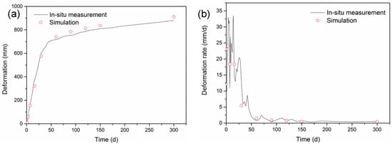
Figure 6.
Comparison of measured convergence and deformation rate with computed results: (a) convergence; (b) deformation rate.
4. The Numerical Model of the Roadway by JG Support
4.1. The Field Tests of JG
As mentioned above, the JG method can improve the mechanical properties of the soft coal mass and therefore reduce the deformation of the roadway. To examine the applicability of the JG, a field test was conducted (shown in Figure 7a). With the drill stem withdrawing in the drilling hole (reverse speed of 20 cm/min), the high-pressure cement grout (23 MPa) with a high jet velocity rotated and cut the coal mass (rotating speed of 18 r/min), then mixed with coal particles, and, finally, a coalcrete column was formed. In the field, parts of the soft coal mass around the roadway profile (approximately 400–600 mm in range (Figure 7b)) could be replaced by coalcrete after JG application. This meets the requirements of a roadway support system by coalcrete columns and indicates that the JG technique in a soft coal mass is practicable and promising.
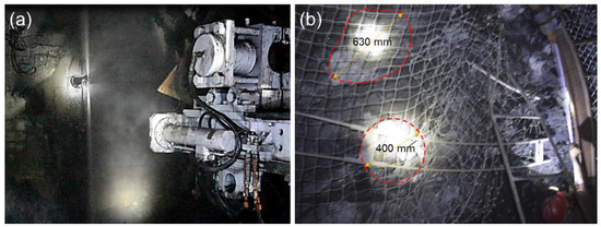
Figure 7.
Jet Grouting (JG) tests in the field: (a) JG tests; (b) the formed coalcrete in the soft coal mass.
4.2. Mechanical Parameters of Coalcrete
The coalcrete is a composite with high strength and a high deformation modulus. Considering its size effect, a series of shear tests and compressive tests with various sizes of specimens were carried out to determine mechanical parameters (Figure 8). The coalcrete specimens (50, 100, 150, 200 mm) were prepared in the laboratory (shown in Figure 8a). The cohesion and friction angle of coalcrete were obtained by shear tests (Figure 8b), and the deformation modulus and compressive strength were gained by uniaxial compressive tests (Figure 8c). Furthermore, according to the fitting functions mentioned in the literature [33,34], the empirical equations, reflecting the size effect on the strength properties of coalcrete, were further established. By using these equations, the mechanical parameters of coalcrete with 400 mm in diameter were determined and are given in Table 4.
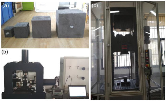
Figure 8.
The prepared specimens and test machines: (a) typical specimens for tests; (b) high-precision servo-hydraulic shear test apparatus; (c) compression testing machine.
Table 4.
The mechanical parameters of coalcrete.
4.3. Numerical Modeling of JG Support
Based on the validated numerical model, the field test results of JG, and the mechanical properties of coalcrete, a JG support system, including jet-grouted coalcrete columns, rock bolts, and U-shaped steel sets, was proposed and further modeled in FLAC3D to examine its control effect on roadway stability (Figure 9a). In coalcrete columns, the M–C model was employed, and the minimum size of elements was set as 0.1 m to minimize the size effect (Figure 9b). In this model, the stress conditions, boundary domain, constitutive model, and support materials such as shotcrete, rock bolts, and U shed were consistent with the original model (shown in Figure 5). To investigate the positive effect of coalcrete in controlling roadway stability, the time-dependent behavior of the surrounding coal mass was simulated for 300 days. The observation points (shown in Figure 9b) monitored the displacement.
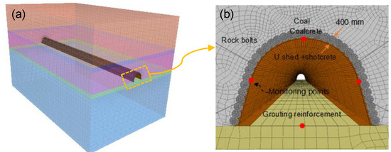
Figure 9.
JG support for rheological coal roadway: (a) the established 3D model of JG; (b) the proposed JG support system.
5. Stability Analysis of Rheological Roadway by JG support
After the installation of the JG support system, the roadway deformation, stress states, and plastic zones around the roadway were studied to reveal its control effect on roadway stability. Therefore, some typical days after roadway excavation were selected (i.e., 3 days, 15 days, 30 days, 300 days) for further analysis and comparison.
5.1. The Deformation of the Roadway by JG Support
The horizontal displacement of the roadway after JG support is depicted in Figure 10. As can be seen, with the increase in time, the moving areas of the sidewalls of the roadway gradually expanded (Figure 10a,b). After 15 days, the movement of the two sidewalls was not obvious. From 30 to 300 days, the horizontal displacement increased slowly (Figure 10c,d). The movement range of the surrounding coal mass was basically unchanging, and the displacement values were relatively small in this period.
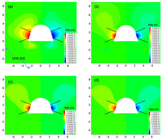
Figure 10.
The horizontal displacement of the roadway by JG support with time: (a) 3 days; (b) 15 days; (c) 30 days; (d) 300 days.
The vertical displacement of the roadway after JG support is displayed in Figure 11. It can be seen from Figure 11a that, after the excavation of the roadway (3 days), the displacement of the floor was obvious, and that value accounted for the majority of the total floor deformation. With the increase in time, the roof and shoulder of the roadway also began to deform (Figure 11b). After 15 days, the deformation around the roadway was basically stable (Figure 11c). By 300 days, the vertical deformation of the roadway did not increase significantly, and only the movement area in the coal mass slightly expanded, owing to the long-term creep behavior of the soft coal mass on the roof (Figure 11d).
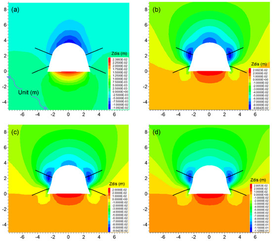
Figure 11.
The vertical displacement of the roadway by JG support with time: (a) 3 days; (b) 15 days; (c) 30 days; (d) 300 days.
Furthermore, the monitoring displacements of the two sidewalls, roof, and floor over time are shown in Figure 12. It is clear that the tendency of roadway deformation was divided into two stages (Stages I and II). In Stage I, within 15 days, the cumulative deformations of the sidewall and roof were just 83 mm and 76 mm, respectively. Interestingly, there was no obvious decelerating rheology of the roadway by JG support at this stage. At Stage II, the coal mass in the deep sidewalls experienced slow rheology, and the time-dependent deformation only accounted for about 15% of the total displacement (100 mm). In terms of the development of roof displacement in this stage, the rheological deformation only accounted for about 5% of the total displacement (80 mm). It is interesting to note that the deformation of the floor was not obvious and was consistent with traditional support. This is because most of the areas in the floor were not in support, and therefore parts of rock mass still failed. It should be pointed out that, although failure happened, the residual strength of the rock mass was still high, and consequently the value of the floor heave was very small (28 mm) in all stages.
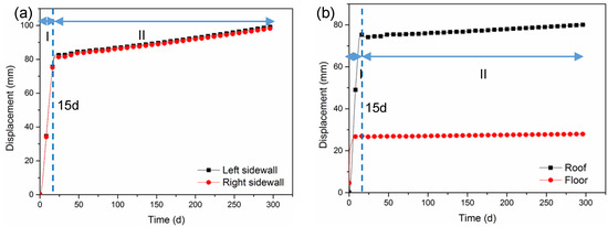
Figure 12.
The roadway deformation of the sidewalls, roof, and floor; (a) deformation of the left and right sidewall; (b) deformation of roof and floor.
Generally, the results showed that, for the horizontal and vertical displacement of the roadway, the JG support scheme was effective for restraining the rheological deformation, reducing the total displacement and stabilization time of the roadway. Specifically, compared with the conventional support system, after JG support, the roof-to-floor convergence reduced from 197 mm to 107 mm: a 45% reduction. The sidewall convergence of the roadway by JG support decreased from 880 mm to 310 m: a 65% reduction. The stabilization time reduced from 60 days to 15 days: a 75% reduction.
5.2. The Stress States around the Roadway by JG Support
The distribution of the maximum principal stress around the roadway by JG support is depicted in Figure 13. After the roadway excavation, a large stress release zone appeared as there was no effective support on the floor (Figure 13a). At the same time, the stress concentration appeared on the two sides of the roadway. Then, the high stress transferred from the shallow sidewalls to the internal sidewalls, roadway vault and roadway shoulders (Figure 13b), forming stress concentration zones. Such behavior of stress movement showed that some yield failures of JG columns in sidewalls occurred, while the JG columns in the roof still had a bearing capacity. From 30 days to 300 days (Figure 13c to 13d), due to the slow creep behavior of the coal mass, the range of the stress release zone and stress concentration area slightly increased.
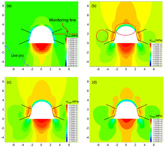
Figure 13.
The maximum principle distribution around the roadway by JG support with time: (a) 3 days; (b) 15 days; (c) 30 days; (d) 300 days.
In addition, a monitoring line (shown by a red dashed line in Figure 13a) was set in the middle of the roadway to obtain the changes in maximum principal stress with time (1, 3, 7, 15, 30, 60, 150, 300 days). The monitoring results are shown in Figure 14. As can be seen, the stress in the coalcrete column increased with the distance to the roadway surface (about 0.4 m within the JG columns). With the increase of time, the peak value of stress in JG columns gradually decreased, indicating that the JG columns gradually failed, and the corresponding bearing capacity decreased. However, the minimum peak value in the JG column was about 15 MPa, which was far greater than 4.9 MPa in the coal mass (reflecting the bearing capacity of the coal mass). With the increase in the distance from the roadway surface, the maximum principal stress in the coal mass gradually increased, until the second peak value of stress (22.08 MPa). This value in the coal mass was close to the initial stress (19.2 MPa), demonstrating that a lower stress concentration accumulated in the coal mass, and therefore JG support optimized the stress conditions around the roadway effectively.
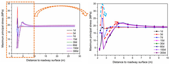
Figure 14.
The changes in the maximum principal stress along the monitoring lines with time.
The distribution of the minimum principal stress around the roadway by JG support is illustrated in Figure 15. After roadway excavation (Figure 15a), there were no tensile stresses in the surrounding rock mass, due to the reinforcement effect of the bottom corner of the roadway. However, there was still a large stress release zone in the floor as parts of the floor failed. With the increase in time, some small stress concentration areas gradually appeared near the roof and bottom corner of the roadway and basically remained stable (Figure 15b). From 30 to 300 days (Figure 15c to 15d), these areas were slightly enlarged by the rheological effect of the coal mass, but the stress concentration areas were not obvious, signifying that the JG support system can optimize the minimum principal stress around the roadway efficiently.
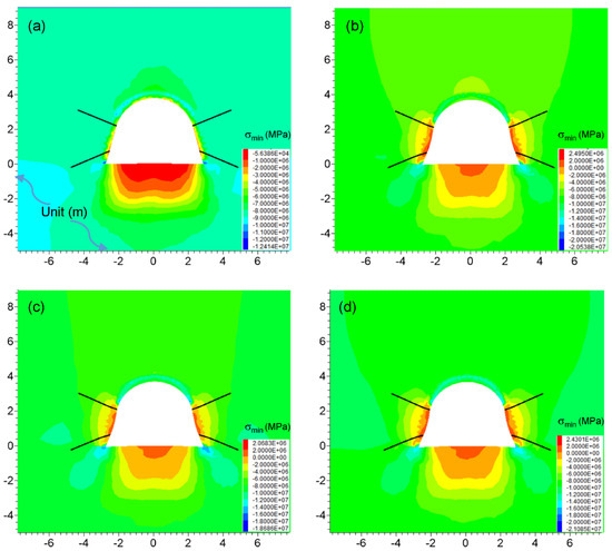
Figure 15.
The minimum principle around the roadway by JG support with time: (a) 3 days; (b) 15 days; (c) 30 days; (d) 300 days.
5.3. The Development of Plastic Zones of the Roadway by JG Support
The development of the plastic zone around the roadway with time is depicted in Figure 16. After excavation (Figure 16a), there was no obvious damage on the roadway vault, but most parts of the floor failed. With the increase in time (Figure 16b), the plastic zone extended into the sidewalls, and the roof was also damaged to a small extent. The development of the plastic zone was basically in a stable state in this period. The failure zones of the roof, floor, and sidewalls did not noticeably expand from 30 to 300 days (Figure 16c to 16d). It is noted that, even at 300 days, the failure areas in the sidewalls were still within the anchoring range of the rock bolts, which avoided the sudden collapse of sidewalls. It should be pointed out that the plastic zones around the roadway cannot be eliminated absolutely. The most economic and efficient way is to stabilize the damage zone into a reasonable range. Overall, the proposed JG support system can reduce the plastic zone to a controllable extent and maintain the long-term stability of the roadway.
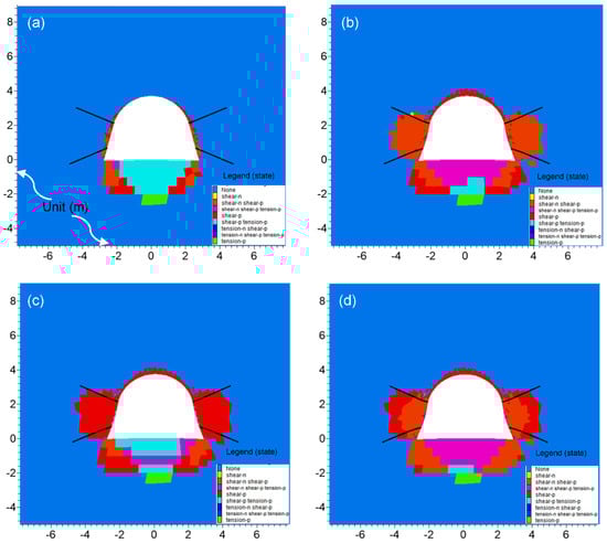
Figure 16.
The development of the plastic zone around the roadway by JG support with time: (a) 3 days; (b) 15 days; (c) 30 days; (d) 300 days.
6. Conclusions
In this study, based on the laboratory creep test of the coal specimen and field measurement of the roadway, the rheological behavior of the soft coal roadway was revealed. A time-dependent 3D numerical model was established and validated by in-situ roadway displacement. According to the field tests of Jet Grouting (JG), a numerical model of the rheological roadway by JG support was further generated and investigated systematically. The mechanism of JG support on roadway stability was revealed by analyzing the roadway deformation, stress distribution, and plastic zones of the roadway. The main results of the study are as follows:
- According to the geological setting, the soft coal mass had a negative effect on the roadway stability. The creep test results showed that the soft coal specimen exhibited a two-stage creep behavior, i.e., decelerating creep and uniform creep.
- Based on the in-situ measurements, the roadway deformation also demonstrated two-stage rheological behavior. A large rheological deformation with a large deformation rate occurred, and the conventional support system could not control the stability of the roadway.
- A CVISC model was adopted in a 3D numerical model to simulate the rheological properties of the roadway. Based on the field measurement, the model was validated, confirming that the input parameters and the time-dependent model were reasonable and accurate.
- As per JG tests in the field and laboratory, a numerical model of the roadway with JG support was proposed, and its control effect on roadway stability was systematically analyzed. The results showed that the JG support could efficiently reduce roadway deformation, optimize the stress conditions and reduce the extent of the plastic zone. The rheological properties of soft coal roadways were constrained, and the long-term stability was guaranteed by JG support.
Author Contributions
Conceptualization by Y.S. and G.L.; methodology, D.Q.; investigation, J.Z.; writing—original draft preparation, Y.S.; writing—review and editing, G.L., D.Q., J.Z.; supervision, G.L.; funding acquisition, G.L.
Funding
This research was supported by the projects of “National Key Research and Development Program (2016YFC0600901)”, “National Natural Science Foundation of China (Grant No.51574224, 51704277)”.
Acknowledgments
The authors are grateful to Huaibei Mining (Group) Co. Ltd. Special thanks to the reviewers’ comments and editor’s work. Special thanks to Dr Zuqi Wang for her encouragement and help.
Conflicts of Interest
The authors declare no conflict of interest.
Abbreviations
| JG | Jet Grouting |
| σ | Constant loading |
| t | Time |
| ε | Strain |
| ηM | Maxwell viscosity |
| GM | Maxwell shear modulus |
| ηK | Kelvin viscosity |
| GK | Kelvin shear modulus |
| CVISC | Burger-creep visco-plastic model |
| M-C | Mohr-Coulomb |
| RMR | Rock mass rating |
| GSI | Geological strength index |
| mb | Rock mass constants |
| σcm | Uniaxial compressive strength of rock mass |
| σt | Tensile strength |
| D | The disturbance factor |
| c | Cohesion |
| ϕ | Friction angle |
| γ | Unit weight of the rock mass |
| ν | Poisson’s ratio |
| Ei | Intact rock modulus |
References
- Zhang, Z.; Shimada, H.; Sasaoka, T.; Hamanaka, A. Stability control of retained goaf-side gateroad under different roof conditions in deep underground y type longwall mining. Sustainability 2017, 9, 1671. [Google Scholar] [CrossRef]
- Wagner, H. Deep Mining: A Rock Engineering Challenge. Rock Mech. Rock Eng. 2019, 52, 1417–1446. [Google Scholar] [CrossRef]
- Yang, F.; Zhang, C.; Zhou, H.; Liu, N.; Zhang, Y.; Azhar, M.U.; Dai, F. The long-term safety of a deeply buried soft rock tunnel lining under inside-to-outside seepage conditions. Tunn. Undergr. Sp. Technol. 2017, 67, 132–146. [Google Scholar] [CrossRef]
- Szurgacz, D.; Brodny, J. Tests of Geometry of the Powered Roof Support Section. Energies 2019, 12, 3945. [Google Scholar] [CrossRef]
- Szurgacz, D.; Brodny, J. Analysis of the Influence of Dynamic Load on the Work Parameters of a Powered Roof Support’s Hydraulic Leg. Sustainability 2019, 11, 2570. [Google Scholar] [CrossRef]
- Xie, H.; Gao, M.; Zhang, R.; Peng, G.; Wang, W.; Li, A. Study on the Mechanical Properties and Mechanical Response of Coal Mining at 1000 m or Deeper. Rock Mech. Rock Eng. 2019, 52, 1475–1490. [Google Scholar] [CrossRef]
- Sainoki, A.; Tabata, S.; Mitri, H.S.; Fukuda, D.; Kodama, J. ichi Time-dependent tunnel deformations in homogeneous and heterogeneous weak rock formations. Comput. Geotech. 2017, 92, 186–200. [Google Scholar] [CrossRef]
- Lee, C.L.; Shou, K.J.; Chen, S.S.; Zhou, W.C. Numerical analysis of tunneling in slates with anisotropic time-dependent behavior. Tunn. Undergr. Sp. Technol. 2019, 84, 281–294. [Google Scholar] [CrossRef]
- Yang, S.Q.; Chen, M.; Jing, H.W.; Chen, K.F.; Meng, B. A case study on large deformation failure mechanism of deep soft rock roadway in Xin’An coal mine, China. Eng. Geol. 2017, 217, 89–101. [Google Scholar] [CrossRef]
- Jiao, Y.Y.; Song, L.; Wang, X.Z.; Coffi Adoko, A. Improvement of the U-shaped steel sets for supporting the roadways in loose thick coal seam. Int. J. Rock Mech. Min. Sci. 2013, 60, 19–25. [Google Scholar] [CrossRef]
- Kang, H.P.; Lin, J.; Fan, M.J. Investigation on support pattern of a coal mine roadway within soft rocks—A case study. Int. J. Coal Geol. 2015, 140, 31–40. [Google Scholar] [CrossRef]
- Yu, W.; Wang, W.; Chen, X.; Du, S. Field investigations of high stress soft surrounding rocks and deformation control. J. Rock Mech. Geotech. Eng. 2015, 7, 421–433. [Google Scholar] [CrossRef]
- Li, S.C.; Wang, H.T.; Wang, Q.; Jiang, B.; Wang, F.Q.; Guo, N.B.; Liu, W.J.; Ren, Y.X. Failure mechanism of bolting support and high-strength bolt-grouting technology for deep and soft surrounding rock with high stress. J. Cent. South. Univ. 2016, 23, 440–448. [Google Scholar] [CrossRef]
- Ghorbani, M.; Sharifzadeh, M. Long term stability assessment of Siah Bisheh powerhouse cavern based on displacement back analysis method. Tunn. Undergr. Sp. Technol. 2009, 24, 574–583. [Google Scholar] [CrossRef]
- Sharifzadeh, M.; Tarifard, A.; Moridi, M.A. Time-dependent behavior of tunnel lining in weak rock mass based on displacement back analysis method. Tunn. Undergr. Sp. Technol. 2013, 38, 348–356. [Google Scholar] [CrossRef]
- Nadimi, S.; Shahriar, K. Experimental creep tests and prediction of long-term creep behavior of grouting material. Arab. J. Geosci. 2014, 7, 3251–3257. [Google Scholar] [CrossRef]
- Nadimi, S.; Shahriar, K.; Sharifzadeh, M.; Moarefvand, P. Triaxial creep tests and back analysis of time-dependent behavior of Siah Bisheh cavern by 3-Dimensional Distinct Element Method. Tunn. Undergr. Sp. Technol. 2011, 26, 155–162. [Google Scholar] [CrossRef]
- Mishra, B.; Verma, P. Uniaxial and triaxial single and multistage creep tests on coal-measure shale rocks. Int. J. Coal Geol. 2015, 137, 55–65. [Google Scholar] [CrossRef]
- Lu, Y.; Wang, L.; Li, Z.; Sun, H. Experimental Study on the Shear Behavior of Regular Sandstone Joints Filled with Cement Grout. Rock Mech. Rock Eng. 2016, 50, 1321–1336. [Google Scholar] [CrossRef]
- Littlejohn, S. The development of practice in permeation and compensation grouting: A historical review (1802–2002): Part 1 permeation grouting. In Proceedings of the Third International Conference on Grouting and Ground Treatment, New Orleans, LA, USA, 10–12 February 2003; pp. 50–99. [Google Scholar]
- Kang, H. Support technologies for deep and complex roadways in underground coal mines: A review. Int. J. Coal Sci. Technol. 2014, 1, 261–277. [Google Scholar] [CrossRef]
- Tinoco, J.; Gomes Correia, A.; Cortez, P. Application of data mining techniques in the estimation of the uniaxial compressive strength of jet grouting columns over time. Constr. Build. Mater. 2011, 25, 1257–1262. [Google Scholar] [CrossRef]
- Ehsanzadeh, B.; Ahangari, K. A Novel Approach in Estimation of the Soilcrete Column’s Diameter and Optimization of the High Pressure Jet Grouting Using Adaptive Neuro Fuzzy Inference System (ANFIS). Open J. Geol. 2014, 4, 386–398. [Google Scholar] [CrossRef]
- Croce, P.; Flora, A.; Modoni, G. Jet Grouting: Technology, Design and Control; CRC Press: Boca Raton, FL, USA, 2014; ISBN 041552640X. [Google Scholar]
- Asteris, P.G.; Roussis, P.C.; Douvika, M.G. Feed-forward neural network prediction of the mechanical properties of sandcrete materials. Sensors 2017, 17, 1344. [Google Scholar] [CrossRef] [PubMed]
- Sun, Y.; Zhang, J.; Li, G.; Wang, Y.; Sun, J.; Jiang, C. Optimized neural network using beetle antennae search for predicting the unconfined compressive strength of jet grouting coalcretes. Int. J. Numer. Anal. Methods Geomech. 2019, 43, 801–813. [Google Scholar] [CrossRef]
- Basarir, H.; Sun, Y.; Li, G. Gateway stability analysis by global-local modeling approach. Int. J. Rock Mech. Min. Sci. 2019, 113, 31–40. [Google Scholar] [CrossRef]
- Guan, Z.; Jiang, Y.; Tanabashi, Y.; Huang, H. A new rheological model and its application in mountain tunnelling. Tunn. Undergr. Sp. Technol. 2008, 23, 292–299. [Google Scholar] [CrossRef]
- Guan, Z.; Jiang, Y.; Tanabashi, Y. Rheological parameter estimation for the prediction of long-term deformations in conventional tunnelling. Tunn. Undergr. Sp. Technol. 2009, 24, 250–259. [Google Scholar] [CrossRef]
- Hoek, E.; Carter, T.G.; Diederichs, M.S. Quantification of the geological strength index chart. In Proceedings of the 47th US rock mechanics/geomechanics symposium, San Francisco, CA, USA, 23–26 June 2013. [Google Scholar]
- Hoek, E.; Marinos, P.G.; Marinos, V.P. Characterisation and engineering properties of tectonically undisturbed but lithologically varied sedimentary rock masses. Int. J. Rock Mech. Min. Sci. 2005, 42, 277–285. [Google Scholar] [CrossRef]
- Hoek, E.; Diederichs, M.S. Empirical estimation of rock mass modulus. Int. J. Rock Mech. Min. Sci. 2006, 43, 203–215. [Google Scholar] [CrossRef]
- Sun, Y.; Zhang, J.; Li, G.; Ma, G.; Huang, Y.; Sun, J.; Wang, Y.; Nener, B. Determination of Young’s modulus of jet grouted coalcretes using an intelligent model. Eng. Geol. 2019, 252, 43–53. [Google Scholar] [CrossRef]
- Sun, Y.; Li, G.; Zhang, J.; Qian, D. Experimental and numerical investigation on a novel support system for controlling roadway deformation in underground coal mines. Energy Sci. Eng. 2019. [Google Scholar] [CrossRef]


© 2019 by the authors. Licensee MDPI, Basel, Switzerland. This article is an open access article distributed under the terms and conditions of the Creative Commons Attribution (CC BY) license (http://creativecommons.org/licenses/by/4.0/).