Abstract
This article focuses on the energy density alteration during non-pillar mining method of goaf-side entry retaining by roof cutting (GERRC) and adjacent working face mining. We also studied the support control strategy of goaf-side roadway. Numerical calculation model is established, and the parameters of the model are verified by the measured advance abutment pressure and numerical solution. Based on the numerical model, the energy density during mining is studied. It is found that the whole energy evolution pattern of the goaf side entry during the two adjacent working face mining includes: the original rock energy, the advance energy of the current working face, the dynamic lateral abutment energy caused by strata movement, the lateral abutment energy of the adjacent working face. The support body failure and surrounding rock large deformation phenomenon often occur in goaf side roadway, which is influenced by multiple energy disturbances. Research shows that strong stress disturbance of surrounding rock generates in front of the working face 23 m and behind of working face 60 m in GERRC method. In the second goaf-side entry retaining, the range is in front of the working face 47 m. The evolution law of energy field puts forward the strategy of using the high constant resistance and large deformation (CRLD) anchor cable and procured preferable effect.
1. Introduction
The goaf-side entry retaining by roof cutting (GERRC) technology can avoid the waste of coal resources and save the cost of tunnel driving [1]. This method is expected to be better applied and improved in China [2]. In this technology, the pre-splitting blasting is carried out in the roadway. In the roof, a pre-cracked structural plane is formed along the strike direction of the working face. Therefore, the stress transfer path between the working face and the roof above the roadway is cut off. Under the action of periodic mine pressure, the roof above the goaf will collapse along the cutting seam. The formed roadway can be used in the next working face. Compared with the traditional coal mining method, no pillar mining has significant technical and economic advantages, such as: (1) the existence of the traditional coal pillar is eliminated, and the recovery rate of resources is improved; (2) it solves the problems of stress concentration caused by coal pillars; (3) the driving cost can be reduced and eliminate the existence of isolated island working face.
Currently, research on GERRC is mainly focused on the key parameter of roof, such as the cutting height, pre-cracking angle, blasting borehole spacing and supporting measures in roadway under different geological conditions. Furthermore, the deformation pattern of roadway surrounding rock and the structure type of roof rock stratum should be analyzed. Zhang et al. [3] demonstrated that the application of GERRC in deep mines can improve the state of roadway stress, thus the superiority and feasibility of this technology is verified. Some scholars studied the key parameters of GERRC, and the calculation method of the cutting height and angle are proposed [4,5,6,7]. He, Gao et al. [1,8] put forward the theory of short beam by cutting roof, and the distribution pattern and the evolution mechanism of GERRC were obtained by the theoretical analysis and field measurement. Meanwhile, the traditional goaf-side entry retaining has made great progress. Xue et al. [9] studied distribution characteristics of roofs stress for goaf-side entry retaining influenced by mining height. Their research obtained the following conclusions: goaf-side entry retaining is in the area of stress decreasing zone; the impact scope and range to the rock becomes more wide with the increase of mining height of working face; the optimal cross-height ratio and the high pre-stress supporting system could be helpful to control the deformation of surrounding rock. Kang, Chen et al. [10,11] analyzed a goaf side entry retaining technology using high strength bolt as the basic support method. At the same time, they put forward the strategy of using hydraulic support to control unstable roadway roof. Zhangnong et al. [12] explained the transfer mechanism of stress, through the analysis of stope overlying strata, and studied pressure relief mechanism of lateral roof presplitting. However, few studies have been published on the roadway stress, energy distribution and deformation in the service period including GERRC progress and the second goaf-side entry stage. In this paper, the GERRC of working face 1200 of Zhongxing coal mine is used as a case study. A 3DEC (3 Dimension Distinct Element Code) numerical model is established to investigate the evolution pattern of three-dimensional stress in the GERRC and adjacent working face mining. In order to ensure the stability of the surrounding rock of the tunnel, the combined support measures are put forward. Constant resistance and large deformation anchor cable and anchor net are used as foundation support. In the area of strong stress disturbance, the deformation of surrounding rock is controlled by the joint action of single hydraulic prop and anchor cable.
2. Case Study
The ZhongXing coal mine 1200 working face is the compound roof in Lvliang City, Shanxi Province, China (Figure 1). There are 14 layers of coal in the mine field, mainly including Shanxi formation of Lower Permian and Taiyuan Formation of Upper Carboniferous. The total thickness of coal bearing stratum is 143.1 m, the total thickness of coal seam is 16.21 m, and the average thickness of minable coal seam is 13.24 m. NNW (North Northwest) fold is relatively developed in coalfield. In this mine, the longwall method is used to coal seam mining at a depth of about 295~397 m. The length of the working face is 190 m and the strike length is 300 m. The cross-section shape of the roadway is a rectangular of 4.5 m × 2.8 m. The total length of roadway is 500 m, of which 142.7 m is constructed by GERRC method (Figure 2). The roof of the mining seam consists of three mudstone layers and two thin coal seams (Figure 3). The coal seam structure is simple, the uniaxial compressive strength is 8.6 MPa. It belongs to the lower Permian Shanxi formation. There is no obvious fault near the working face, and the exposed rock stratum of the roadway roof is relatively broken. Above the coal seam are sandy mudstone, coal, sandy mudstone, coal body and fine sandstone. The uniaxial compressive strength of sandy mudstone is about 22.2~28.9 MPa; the coal is about 8.6~10.3 MPa; the fine sandstone is about 39.2 MPa. The strength of roof above coal seam is weak. The thickness of the direct roof is about 12.8 m. According to the GERRC theory [4,13] GERRC technical progress is introduced in Zhongxing Coal Mine (Figure 4). Before mining face moving, the drill hole process should have been completed. The drill hole inclines 15 degrees, with 6000 mm in depth and 48 mm in diameter. By using smooth blasting technology, the roof can be pre cracked [14]. As shown in Figure 5, After the completion of the working face system, anchor cable and other supporting measures are used for support. After the support is completed, the pre-splitting blasting is carried out to form cracks in the side roof of the goaf. After the working face is mined, the roof of the goaf automatically collapses along the crack under the action of self-weight and mine pressure, forming one side wall of the roadway. The wall can be isolated to the empty area of mining. The goaf-side entry roadway can be regarded as the next working face roadway.
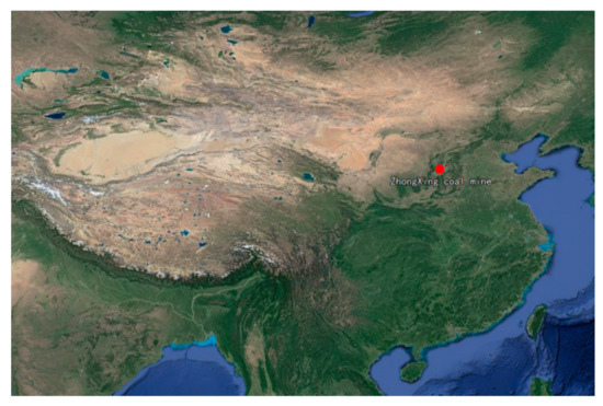
Figure 1.
Mine location.
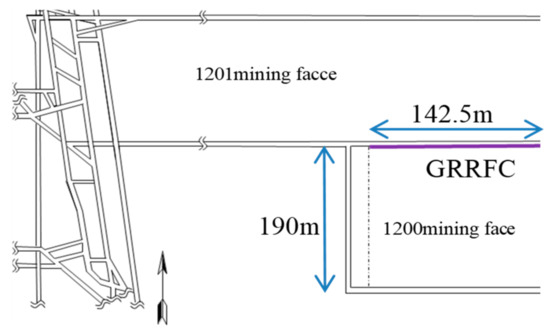
Figure 2.
Layout of working face.
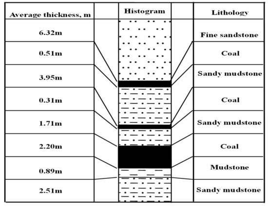
Figure 3.
Lithology of roof and floor.
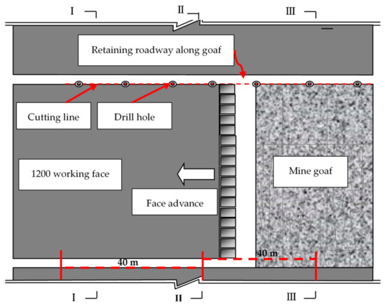
Figure 4.
The plane graph of cutting roof goaf-side entry retaining technical process.
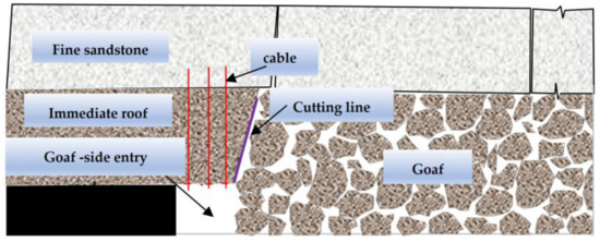
Figure 5.
The section of cutting roof goaf-side entry retaining technical process.
2.1. Numerical Model
The geological properties were taken from ZhongXing coal mine 1200 working face. We choose to use commercial discrete element program 3DEC for numerical simulation analysis, which has been widely used in coal mining [15]. The purpose of the model is to predict the stress distribution and energy evolution after excavation in GERRC. The dynamic stress distribution characteristic and energy evolution were analyzed to propose proper supporting measures. The numerical simulation is based on the model of ubiquitous joints and the bedding is considered, as shown in Figure 6. The dimensions of the 3D model are 500 × 200 × 60 m (length × width × height). The base 3D model consists of 1013840 blocks and 1078650 nodes.
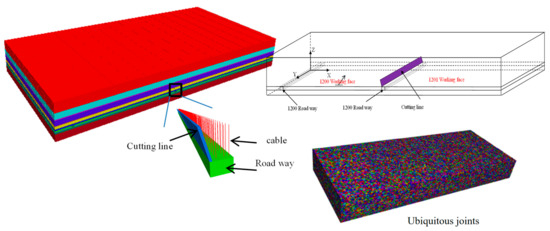
Figure 6.
The 3DEC (3 Dimension Distinct Element Code) numerical simulation model for the goaf-side entry retaining by roof cutting (GERRC).
The problem is solved using a “dynamic solution model” discrete element solution procedure. An automatic “adaptive” viscous damping scheme is developed by Cundall [16] for solution of mining problems involving seismic release of energy. The is the damping power for a node; is the rate of change of nodal kinetic energy; . At , the damping would be reduced. Nonreflecting (or absorbing) boundary is regarded as the boundary condition. Based on the Mohr–Coulomb failure criterion, the yield function is established in the model. The numerical simulation contributes to obtaining the movement pattern of overlying strata, distribution characteristic of energy in stope and stress evolution pattern of roadway roof. Then, the time–space relationship of stress superposition and the excavation would be predicted to decide the roof control strategy in GERRC. According to the ground stress in the geological survey, the horizontal stress in the X direction is 3.5 MPa, and the horizontal stress in the Y direction is 3.5 MPa. The vertical stress is set 8 MPa to represent the gravity of the overlying rock mass.
2.2. Parameter Verification and Analysis of Abutment Pressure
Advanced support pressure of working face is the result of redistribution of original rock stress after underground coal seam mining. Research on advanced support pressure in coal mining process has important reference function for selection of support mode. It is also an important reference for verifying the selection of numerical simulation parameters. The field measured values are mainly adopted by borehole stress meter. The depth of drill hole reaches 10 m. The stress gauge is divided into six groups, each with a spacing of 25 m.
It is not feasible to select the mechanical parameters of engineering rock mass directly using the data obtained from experiments, and the selection of numerical calculation parameters is one of the key problems in geotechnical engineering, which plays a vital role in the calculation results. The selection of parameters not only needs to consider the intrinsic properties of rock such as rock strength, but also needs to combine the occurrence environment and structural characteristics of rock mass. According to the literature ‘Itasca Consulting Group, Inc. 3DEC User Manual; Itasca Consulting Group, Inc.: Minneapolis, MN, USA, 2016’ [17], The selection of rock mechanics parameters needs to satisfy the following formulas.
Formulas: Elastic modulus; Poisson’s ratio; Bulk modulus; G Shear modulus; Joint normal stiffness; Minimum side length of block; Joint tangential stiffness.
In order to compare and verify the relevant rock mechanics parameters selected in Table 1 and Table 2, the abutment pressure distribution is analyzed which is obtained by the measured and numerical methods. The stress data extraction point of the numerical result is consistent with the coordinate position of the measured point, and the result is shown in Figure 7. Through the comparison between the measured data and the numerical data, the parameter values in Table 1 and Table 2 are adjusted. Finally, the mechanical parameters that are more suitable for practical engineering are obtained. The borehole stress meter cannot measure the true earth stress value, but can reflect the stress change law of the measuring point. As shown in Figure 8a, the initial pressure of the borehole stress gauge is 5 MPa. As the distance between the mining face and the monitoring point is shortened to 40–-45m, the abutment pressure begins to increase. The monitoring point reaches the highest pressure when the mining face is 9–12 m, and the maximum value is 45–55 MPa. As the working surface continues to mine, the support pressure value gradually decreases.

Table 1.
Rock mechanics parameters settled in numerical model.
Table 2.
Joint parameters settled in numerical model.
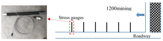
Figure 7.
Installation position of borehole stressmeter.
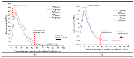
Figure 8.
Abutment pressure comparison. Notes: (a) Measured values of stress gauges; (b) Numerical value.
The numerical simulation can reflect the stress on the monitoring point. As shown in Figure 8b, when the working surface is 48 m away from the measuring point, it begins to enter the abutment pressure influence area. When the distance between the working face and the measuring point is 9–12 m, the maximum abutment pressure is reached. The numerical simulation results are basically consistent with the measured results. Therefore, it can be considered that the simulation method and parameter setting can meet the research needs.
3. Results of Numerical Simulation
The mechanical behavior of the rock mass is related to the mining history and mining process in Mining Engineering. The following steps were adopted to simulate correctly the energy density distribution and stress evolution of roadway roof induced by mining. (1) Computing the initial state of the model under obtained boundary mechanical condition and displacement condition. (2) Simulating the tunnel excavation. (3) Simulating the cutting line excavation. (4) Simulating the mining seam of face 1200 step-by-step, this stage is the process of GERRC. (5) Simulating the mining seam of face 1201. The numerical results show that the roadway is affected by multiple dynamic pressure during the service period.
3.1. Strata Movement
It can be seen from the 3D_z_displacement field (Figure 9) that they are divided into the stable zone and the unstable region in the overlying strata of face 1200 in the GERRC. For example, stratum movement begins to stabilize behind the coal face 60 m when the coal seam is mined on 140 m. The advance influence scope in roadway roof reaches 18 m when the working face 1201 is excavated to 95 m.
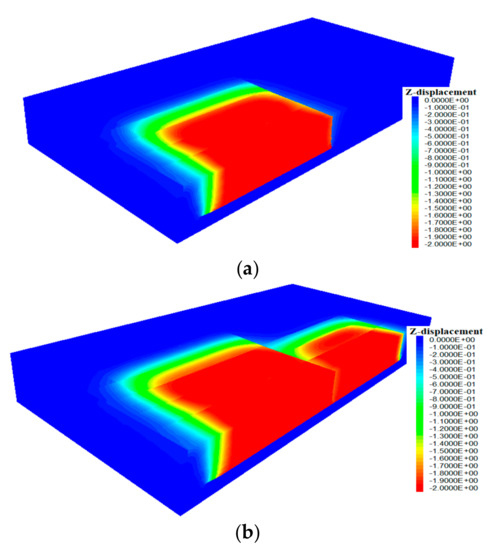
Figure 9.
The 3D_z_displacement field of surrounding rock. Notes: (a) 1200 working face mining; (b) 1201 working face mining.
The displacement nephogram is showed in Figure 10a–d, which were in front of 1200 working face 20, 60 and 100 m and advanced 1201 working face 10 m respectively. The maximum displacement of roadway roof subsidence in 1200 working face mining is 0.26 m. The maximum displacement of roadway roof subsidence in 1201 working face mining is 0.50 m. Figure 10a shows that under the action of mine pressure, after coal seam mining, the upper immediate roof is beginning to collapse. At this time, the movement of rock strata will cause a certain dynamic pressure impact on the roadway. Figure 9b,c represents the process of rock collapse to stability. Figure 10d indicates the deformation characteristics of roadway under the interaction between 1200 and 1201 working faces. The numerical results show that the roof of roadway sinks 0.24 m under the influence of secondary mining.
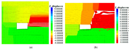
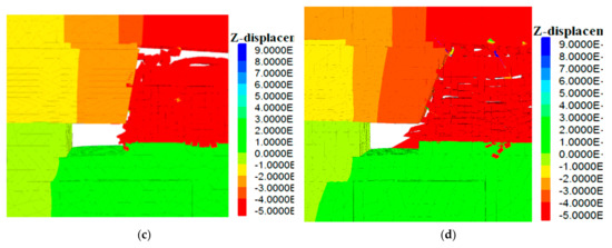
Figure 10.
Displacement diagram of the GERRC process. (a) Immediate roof begin to collapse; (b) Immediate roof Complete collapse; (c) The upper strata began to collapse; (d) Roadway and surrounding rock stability. Notes: (a) Immediate roof begin to collapse; (b) Immediate roof Complete collapse; (c) The upper strata began to collapse; (d) Roadway and surrounding rock stability.
3.2. Energy Density Evolution of Surrounding Rock
The overlying strata movement will induce the new stress distribution and stress distribution of surrounding rock in roadway. Thus the stabilization of roadway is affected [18]. However, due to the anisotropy of rock mass, the state of surrounding rock cannot be adequately reflected through simple stress analysis. Therefore, it is necessary to study the distribution of energy density and the dynamic evolution of stress in mining progress. The strain energy density is completely decided by stress and strain [19,20,21,22], the calculation method is shown in Formula 5. The 3D_energy density field which parallel roadway floor is shown in Figure 11. The unit of stress is MPa. Strain represents the relative change of length. The unit of elastic energy density is J/m3.
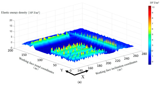
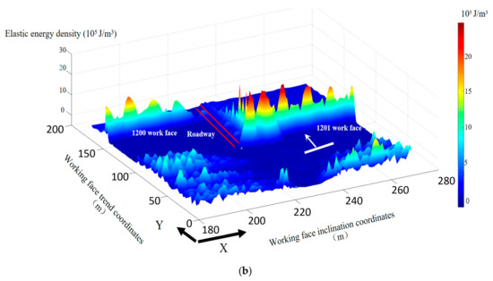
Figure 11.
The 3D_energy density field of surrounding rocks. Notes: (a) The 3D_energy density field in GERRC. (b) The 3D_energy density field in the second goaf-side entry.
(1) The Goaf-Side Entry Retaining by Roof Cutting (GERRC) Process
In the process of GERRC, the elastic energy distribution characteristics are obvious, which are mainly divided into goaf compaction area, stope lateral energy concentration area and ahead workface energy concentration area. About 60 m behind the working face, the overburden strata collapsed stably. Fixed X value and Z value in numerical simulation, the working face is pushed to Y = 150 m, and elastic energy is extracted in the range of X = 180 m, Y = 120 ~ 170 m, forming the energy distribution map, as shown in Figure 12. The peak energy appears at 9 m in front of the working face, the peak elastic energy density is 6.4e5 J/m3, and the influence range of advanced elastic energy is about 23 m.
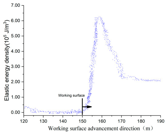
Figure 12.
Energy density distribution along working face.
In order to study the lateral energy distribution in the GERRC stage, the elastic energy distribution at X = 160 ~ 260 m and Y = 60 m is extracted, as shown in Figure 13.
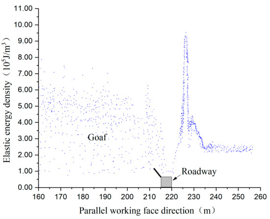
Figure 13.
The lateral energy density distribution.
The area of lateral abutment energy density distribution near the roadway is about 18 m, when coal seam is mined 150 m. The data shows that the maximum energy density of in front of the coal face is about 3.2 times that of the original elastic energy density, and the lateral abutment energy density is 4.6 times of it. The energy density complexly changes behind of the coal face [19,23,24,25]. It is found that the energy density field tended to be stable in the displacement and energy density field when the stratum is beginning to stabilize. Figure 12 shows that the Goaf-side Entry is located in the low stress region, and the peak lateral support stress is located 6 meters apart. The vertical stress fluctuation is mainly affected by the overlying strata movement in a coal mine. During the stress wave spreading process, a dynamic stress loading state will be occurred in roadway roof. Then it could lead to the damage of the support of roadway. Research suggests that there are complex relations among the dynamic stress, roof hanging distance, thickness, and propagation distance of stress wave [19,26].
The dynamic path of roadway roof energy, which located above the roof, the point at Y = 60 m is showed in Figure 14. The evolution law of energy on roadway roof could be divided into three stages in GERRC.
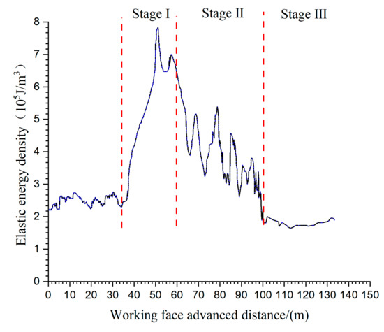
Figure 14.
Evolution law of energy density of roadway roof.
The stage Ⅰ-advanced dynamic energy in front of working face 25 m, stage Ⅱ-dynamic energy behind working face 40 m. The maximum stress of roadway roof is located in stage Ⅰ. It concluded that the stage Ⅰ is generated by advancing support pressure and stratum movement, stage Ⅱ of stress is generated by lateral abutment pressure and stratum movement. In the stage Ⅲ, the dynamic pressure disappears and the energy density returns to a lower level than the original state.
(2) The Second Goaf-Side Entry Retaining
The surrounding rock of the roadway would easily occur instability, which is applied by the lateral abutment pressure of the adjacent working face and the advance abutment pressure of the current working face. As shown in Figure 15, the advance influence scope in roadway roof reached 47 m when working face 1201 is excavated to 95 m. Select the location of roadway roof at y = 80. Figure 15 shows that the front abutment energy the peak is 1.5 × 10⁶ J/m3, which is approximately 2 times that of GERRC operations.
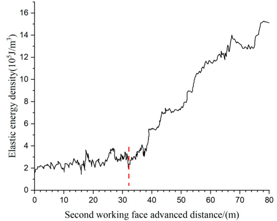
Figure 15.
Energy density of roadway roof (second goaf-side entry retaining).
4. Proposed Supporting Strategy
4.1. Supporting Measure
- (1).
- In the GERRC progress and the second goaf-side entry retaining progress, the roof of roadway is affected by the in-situ stress and disturbed stress. The high constant resistance and large deformation (CRLD) anchor cable has a huge advantage in resistant to dynamic loading. Therefore, the high CRLD anchor cable is selected to control the deformation and damage of surrounding rock.
- (2).
- The stress state and mechanical property of surrounding rock could be improved by the increasing pretension of bolting. It contributes to keep the stability of the roadway roof.
- (3).
- The numerical simulation result shows that intense stress disturbance region of surrounding rock is in front of the working face 17 m and behind working face 55 m in GERRC. In the second goaf-side entry retaining, the range is in front of the working face 45 m. Improving roadway supporting (hydraulic support) is used to control the surrounding rock deformation in stress disturbance region.
The maximum support resistance of high CRLD anchor cable is 300 KN. The pretension of this bolting can reach 200~270 KN. And it could span 405.38 mm under higher support resistance. As shown in Figure 16 and Figure 17, it has good resistance to high stress dynamic load [27,28].
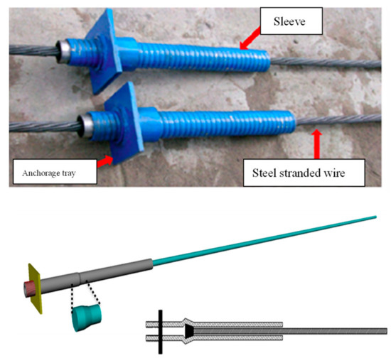
Figure 16.
High constant resistance and large deformation (CRLD) anchor cable.
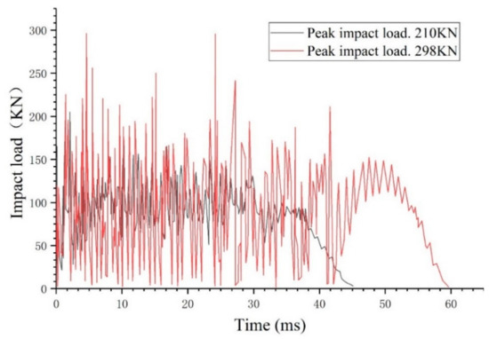
Figure 17.
Dynamic impact test of anchorage cable.
4.2. Reinforcement System for Roadway
Based on numerical simulation and theoretical analysis, an improving support system for roadway is proposed as shown in Figure 18. Detailed build process is as follows:
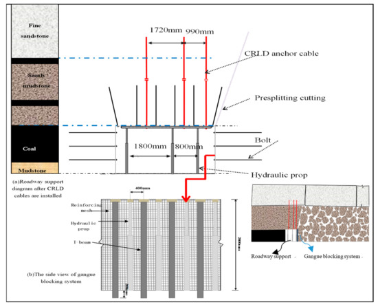
Figure 18.
Support system for roadway.
- (1)
- When the roadway excavation, the roof of the roadway is supported by withthread steel cable, CRLD anchor cable and mesh. The thread steel cable is 20 mm in diameter and 1.1 m in length, and the inter-row space is set to 0.86 m 1 m. Furthermore, three CRLD anchor cables (= 21.6 mm, = 7300 mm) were set in the roadway roof, which the inter-row space is set to 1.72 m 1 m and 0.99 m 1 m. The pre-tightening force of the CRLD anchor cable is set to 200 KN. This step could contribute to improve the strength of the rock mass and prevent collapse of the roadway roof. The CRLD anchor cable also contributed to restrict dynamic load.
- (2)
- In the progress of GERRC, the combined support with thread steel cable, CRLD anchor cable, mesh, and the hydraulic prop (rated working resistance, 294 KN. initial work resistance: 114–154 KN. maximum support height: 2.24 m. minimum support height: 1.44 m, column travel: 0.8 m) were installed in disturbed stress zone, which is located in front of working face 17 m and behind working face 60 m.
- (3)
- In the second goaf-side entry retaining, the hydraulic prop is installed in front of working face 45 m.
Furthermore, hydraulic prop + I-beam+ reinforcing mesh were applied in roadside to avoid the gangue entering the roadway. As shown in Figure 19, the good application result is achieved.
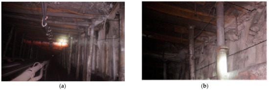
Figure 19.
Goaf-side entry retaining through releasing pressure by roof-cutting. Notes: (a) support layout of roadway; (b) gangue wall forms one side of the roadway.
5. Monitoring Results
5.1. The Subsidence Displacement of Roof
The stability of roadway could be analyzed by subsidence displacement of roof. It could be used to observe the effect of support system. Selecting the monitoring points corresponding to the numerical simulation, the monitoring points is set to 20 m (section A), 60 m (section B) and 100 m (section C) in the place ahead the starting position of GERRC respectively. The results were shown in Figure 20. During the GERRC process, the deformation of roadway is obviously divided into three stages. The first stage Ⅰ starts from the 30 m ahead of the working face, and the deformation of the roadway is 30 mm. In the second stage Ⅱ, the roadway deformation increased to 70 mm. Behind the working face 40 m, the roof of the roadway is relatively stable. In the second mining face, the deformation of roadway begins at 60 m ahead of the face, and the maximum deformation is 120 mm.
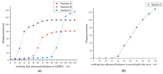
Figure 20.
Roof subsidence. Notes: (a) deformation curve of roadway roof in the process of GERFC; (b) deformation curve of roadway roof in the process of second mining.
5.2. Axial Force of the CRLD Anchor Cable
Vibration wires pressure sensor is used to measure the axial force of the CRLD anchor cable. The measured results were shown in Figure 21. All axial force of the cable increases gradually with working face distance in front of working face 15–18 m., The axial force of the CRLD anchor cable is confined to the max-loading condition (300 KN) behind working face 0–30 m. The anchor cable will be constant resistance deformation when the force is greater than 300 KN. Due to the force of CRLD anchor cable had already reach maximum supporting resistance in GERRC, and the force would not observably change in second goaf-side entry. However, the tensile constant resistance deformation of the anchorage cable appeared.
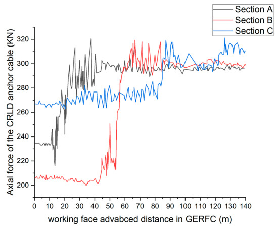
Figure 21.
Axial force of the constant resistance and large deformation (CRLD) anchor cable.
6. Conclusions
In this paper, the characteristics of energy distribution and stability control of surrounding rock in GERRC are the main research contents. The laws of strata movement, deformation of surrounding rock, energy evolution and roadway stability control countermeasures are analyzed.
The results of numerical simulation and field monitoring show that the stress in roadway roof could be divided into three stages. In the second goaf-side entry retaining, advancing pressure is significantly increased, compared with the GERRC.
The research shows that in the process of GERRC, on the basis of the original support measures, the temporary support means should be adopted. The key control area is 23 m ahead of the working face and 60 m behind the working face. In the secondary mining process, the area is about 47 m ahead of the working face.
Based on the study of energy distribution characteristics of this method, a reasonable support design scheme is proposed. Across the numerical simulation and monitoring result, the combination supporting method and dynamic staged control strategy can effectively control the deformation of roadway.
According to the research of this paper, GERRC technology can effectively reduce the energy concentration around the roadway, thus avoiding such phenomena as large deformation of soft rock, roof instability, floor heave and so on, which ensures the safety of coal mining from the technical level. Compared with common mining and driving methods, GRRFC method can effectively saving coal resources due to no pillar mining. The strategy can reduce the amount of tunnel excavation, save the cost of excavation, and reduce the accidents caused by excavation.
Author Contributions
Conceptualization, L..L. and G.L.; Methodology, G.L.; Software, G.L.; Validation, L.L., W.G.;Formal Analysis, W.G.; Investigation, L.L.; Resources, G.L.;Data Curation, G.L.; Writing Original Draft Preparation, L.L.; Writing Review & Editing, L.L.; Visualization, J.W., H.D.; Supervision, W.G.; Project Administration, L.L.; Funding Acquisition, L.L.
Funding
This research was funded by [National Natural Science Foundation of China] grant number [No. 51574248], and [Guizhou Department of Education Youth Talent Growth Project of China] grant number [No. [2019]161 and [2019]162], [Guizhou Science and Technology Plan Project of China] grant number [No. [2018]5622].
Conflicts of Interest
The authors declare no conflicts of interest.
References
- Wang, Y.; Gao, Y.; Wang, E.; He, M.; Yang, J. Roof Deformation Characteristics and Preventive Techniques Using a Novel Non-Pillar Mining Method of Gob-Side Entry Retaining by Roof Cutting. Energies 2018, 11, 627. [Google Scholar] [CrossRef]
- He, M.C.; Zhu, G.L.; Guo, Z.B. Longwall mining “cutting cantilever beam theory” and 110 mining method in China—The third mining science innovation. J. Rock Mech. Geotech. Eng. 2015, 7, 483–492. [Google Scholar] [CrossRef]
- Zhang, G.F.; Man-Chao, H.E.; Xue-Ping, Y.U.; Zheng-gu, H. Research on the Technique of No-Pillar Mining with Gob-Side Entry Formed by Advanced Roof Caving in the Protective Seam in Baijiao Coal Mine. J. Min. Saf. Eng. 2011, 28, 511–516. [Google Scholar]
- Sun, X.; Liu, X.; Liang, G.; Wang, D.; Jiang, Y.L. Key parameters of gob-side entry retaining formed by roof cut and pressure releasing in thin coal seams. Chin. J. Rock Mech. Eng. 2014, 33, 1449–1456. [Google Scholar]
- Guo, Z.; Wang, J.; Cao, T.; Chen, L.; Wang, J. Research on key parameters of gob-side entry retaining automatically formed by roof cutting and pressure release in thin coal seam mining. J. China Univ. Min. Technol. 2016, 45, 879–885. [Google Scholar]
- Zhang, G.; Xu, Y.; Ge, P. Research on cut gob-side entry retaining in thin coal seam of Tangshan ditch. Chin. J. Rock Mech. Eng. 2016, 35, 1397–1406. [Google Scholar]
- Cai, F.; Miao, P.; Wang, E.; Wang, J. Fracture condition and moving rule of surrounding rocks in the joint cutting immediate roof of thick-layer limestone. Caikuang Yu Anquan Gongcheng Xuebao. J. Min. Saf. Eng. 2017, 34, 488–494. [Google Scholar]
- Manchao, H.E.; Gao, Y.; Yang, J.; Guo, Z.; Wang, E.; Wang, Y. An energy-gathered roof cutting technique in no-pillar mining and its impact on stress variation in surrounding rocks. Chin. J. Rock Mech. Eng. 2017, 36, 1314–1325. [Google Scholar]
- Xue, J.H.; Han, C.L. Strata Behavior and Control Countermeasures for the Gob-Side Entry Retaining in the Condition of Large Mining Height. J. Min. Saf. Eng. 2012, 29, 466–473. [Google Scholar]
- Chen, Y.; Bai, J.B.; Wang, X.Y.; Ma, S.Q.; Xu, Y.; Bi, T.F.; Yang, H.Q. Support technology research and application inside roadway of gob side entry retaining. J. China Coal Soc. 2012, 37, 903–910. [Google Scholar]
- Kang, H.; Niu, D.; Zhen, Z.; Lin, J.; Li, Z. Deformation characteristics of surrounding rock and supporting technology of gob-side entry retaining in deep coal mine. Chin. J. Rock Mech. Eng. 2010, 29, 1977–1987. [Google Scholar]
- Zhang, N.; Han, C.L.; Han, J.G.; Zhang, X.G. Theory and practice of surrounding rock control for pillarless gob-side entry retaining. J. China Coal Soc. 2014, 39, 1635–1641. [Google Scholar]
- Gao, Y.; Liu, D.; Zhang, X.; He, M. Analysis and Optimization of Entry Stability in Underground Longwall Mining. Sustainability 2017, 9, 2079. [Google Scholar] [CrossRef]
- He, M.; Cao, W.; Shan, R.; Wang, S. Blasting technology—Bilateral cumulative tensile explosion. Chin. J. Rock Mech. Eng. 2003, 22, 2047–2051. [Google Scholar]
- Gao, F.; Stead, D. Discrete element modelling of cutter roof failure in coal mine roadways. Int. J. Coal Geol. 2013, 116, 158–171. [Google Scholar] [CrossRef]
- Cundall, P.A. Adaptive density-scaling for time-explicit calculations. In Proceedings of the 4th International Conference on Numerical Methods in Geomechanics (Edmonton 1982), Edmonton, AB, Canada, 31 May–4 June 1982. [Google Scholar]
- Itasca Consulting Group, Inc. 3DEC User Manual; Itasca Consulting Group, Inc.: Minneapolis, MN, USA, 2016. [Google Scholar]
- Bai, J.B.; Shen, W.L.; Guo, G.L.; Wang, X.Y.; Yu, Y. Roof Deformation, Failure Characteristics, and Preventive Techniques of Gob-Side Entry Driving Heading Adjacent to the Advancing Working Face. Rock Mech. Rock Eng. 2015, 48, 2447–2458. [Google Scholar] [CrossRef]
- Yang, W.; Lin, B.Q.; Qu, Y.A.; Li, Z.W.; Zhai, C.; Jia, L.L.; Zhao, W.Q. Stress evolution with time and space during mining of a coal seam. Int. J. Rock Mech. Min. Sci. 2011, 48, 1145–1152. [Google Scholar] [CrossRef]
- Xu, Z. Mechanics of Elasticity, 4th ed.; Higher Education Press: Beijing, China, 2006. [Google Scholar]
- Sun, X.L.; Liu, J.B.; Zhu, H. Correlational fractal characterisation of stress and acoustic emision during coal and rock failure under multilevel dynamic loading. Int. J. Rock Mech. Min. Sci. 2019, 117, 1–10. [Google Scholar] [CrossRef]
- Maleki, H.N.; Weaver, A.; Acre, R. Stress-Induced Stability Problems—A Coal Mine Case Study. In Proceedings of the 32nd US Symposium on Rock Mechanics (USRMS), Norman, OK, USA, 10–12 July 1991. [Google Scholar]
- Mahdevari, S.; Shahriar, K.; Sharifzadeh, M.; Tannant, D.D. Stability prediction of gate roadways in longwall mining using artificial neural networks. Neural Comput. Appl. 2017, 28, 3537–3555. [Google Scholar] [CrossRef]
- Shi, X.M.; Liu, B.G.; Tannant, D.; Qi, Y. Influence of consolidation settlement on the stability of inclined TBM tunnels in a coal mine. Tunnell. Undergr. Space Technol. 2017, 69, 64–71. [Google Scholar] [CrossRef]
- Du, W.; Jiang, Y.; Ma, Z.; Jiao, Z. Assessment of water inrush and factor sensitivity analysis in an amalgamated coal mine in China. Arab. J. Geosci. 2017, 10, 471. [Google Scholar] [CrossRef]
- He, J.; Dou, L.; Gong, S.; Li, J.; Ma, Z. Rock burst assessment and prediction by dynamic and static stress analysis based on micro-seismic monitoring. Int. J. Rock Mech. Min. Sci. 2017, 93, 46–53. [Google Scholar] [CrossRef]
- He, M.; Guo, Z. Mechanical property and engineering application of anchor bolt with constant resistance and large deformation. Chin. J. Rock Mech. Eng. 2014, 33, 1297–1308. [Google Scholar]
- He, M.; Gong, W.; Wang, J.; Qi, P.; Tao, Z.; Du, S.; Peng, Y. Development of a novel energy-absorbing bolt with extraordinarily large elongation and constant resistance. Int. J. Rock Mech. Min. Sci. 2014, 67, 29–42. [Google Scholar] [CrossRef]


© 2019 by the authors. Licensee MDPI, Basel, Switzerland. This article is an open access article distributed under the terms and conditions of the Creative Commons Attribution (CC BY) license (http://creativecommons.org/licenses/by/4.0/).