1. Introduction
CO
2 is a main greenhouse gas and undoubtedly a major contributor to global warming. Capturing CO
2 from the atmosphere is an essential parameter of the carbon management for sequestrating CO
2 from our environment. The concentration of CO
2 in our atmosphere is promoted by the combustion of fossil fuels for generating electricity [
1,
2]. In addition, the amount of the fly ash produced from power plants is expected to increase continuously as the demand for electricity increases. Thus, the interest in fly ash utilization has increased [
3,
4,
5,
6].
Among many CO
2 reduction and sequestration techniques, solid-looping using calcium oxide (CaO) is a promising CO
2 capture process, known as carbonate looping [
7,
8,
9,
10,
11,
12,
13]. This process is based on the reversible reaction between CaO and CO
2 to form calcium carbonate. The carbonation reaction can be used to remove CO
2 from the atmosphere. Derevschikov et al. prepared a CaO/Y
2O
3 sorbent to capture CO
2 at high temperatures [
14]. J. Shi et al. synthesized a CaO/sepiolite sorbent by the hydration reaction [
15]. However, these manufacturing processes are complex and uneconomical for industrial application.
Meanwhile, solid refused fuel (SRF), a highly heterogeneous mixture of high calorific fraction of non-hazardous waste materials, has been recognized as a viable alternative to fossil fuels, and is already being used as a fuel in various industrial sectors, including power plants [
16]. The fly ash from SRF plants contains about 20 wt% of lime (CaO) which can be used to sequester CO
2 by aqueous carbonation. Thus, studies about utilizing fly ash as a solid sorbent material for CO
2 capture have increased. In the carbonation reaction between CaO and CO
2, water plays an essential role in hydrating the calcium-based materials to form calcium hydroxide and most studies were conducted in environments with a high amount of water. Loo et al. conducted accelerated wet carbonation experiments on circulating fluidized bed combustion (CFBC) ash (the prepared solution possessed an ash-to-water ratio of 1:10) [
17]. Dananjayan et al. and Ebrahimi et al. conducted aqueous carbonation with the water-to-ash ratio of 15:1 with carbonation capacities of 50.3 g and 32 g of CO
2/kg of fly ash, respectively [
18,
19].
However, although a Ca(OH)2 aqueous solution can be effectively used as an absorbent to capture CO2, commercialization of the CO2 capture process is still hindered because of the high amount of energy required to evaporate water. Moreover, the process needs a wastewater treatment plant which can be a source of greenhouse gasses.
In this study, we investigated the utilization of fly ash as a solid sorbent material for CO
2 capture via semi-dry carbonation reaction. The effects of the amount of moisture, CO
2 concentration, and reaction time on the performance of fly ash was investigated. The rest of the paper is structured as follows:
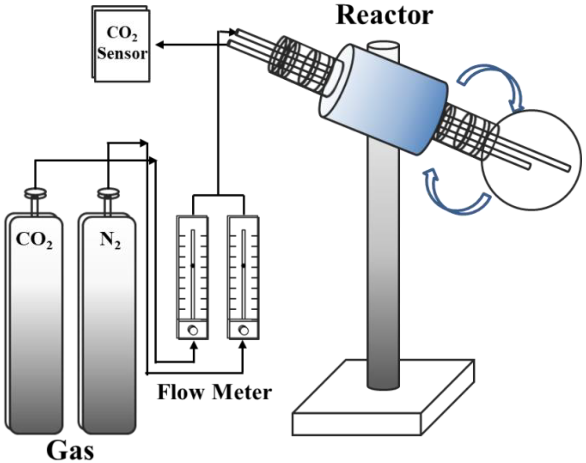
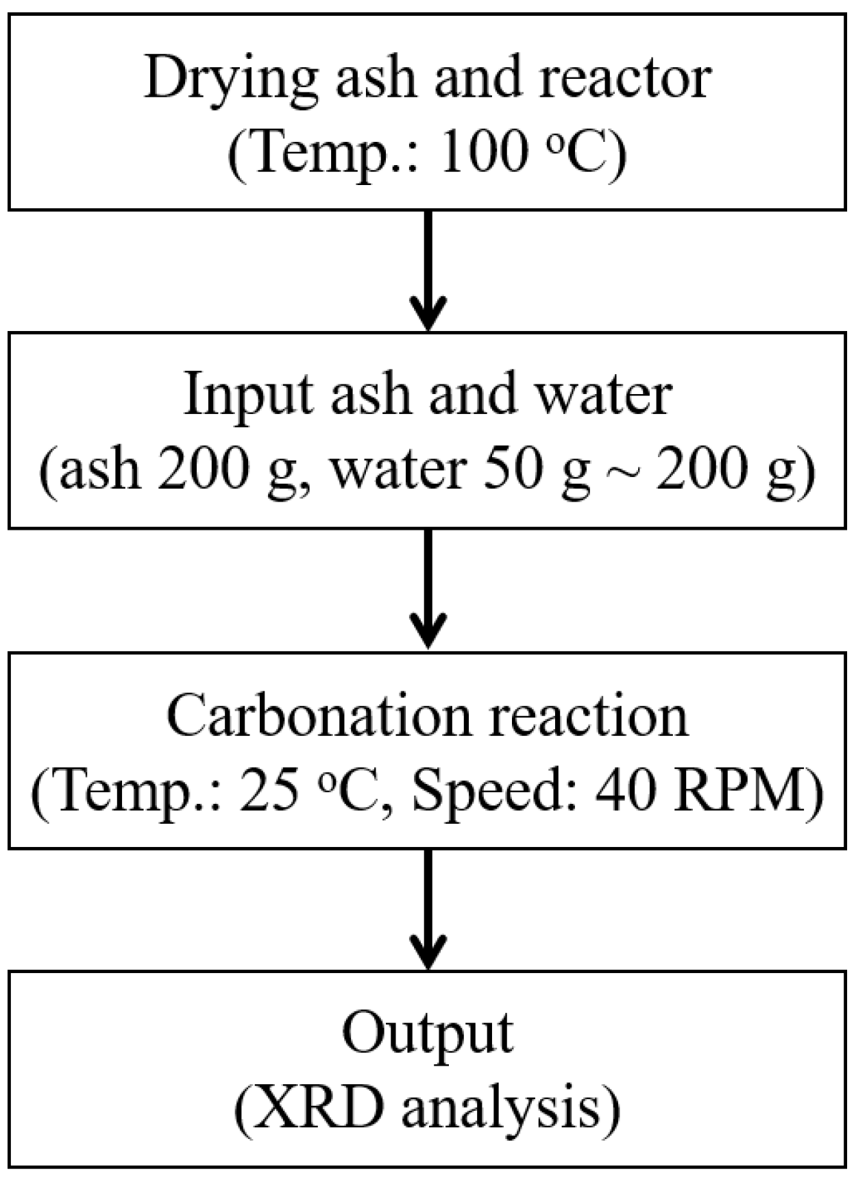
Section 2 describes the experimental framework used to evaluate the semi-dry carbonation.
Section 3 contains the composition changes after the carbonation of SRF ash.
Section 4 and
Section 5 present our discussions and conclusions.
3. Results
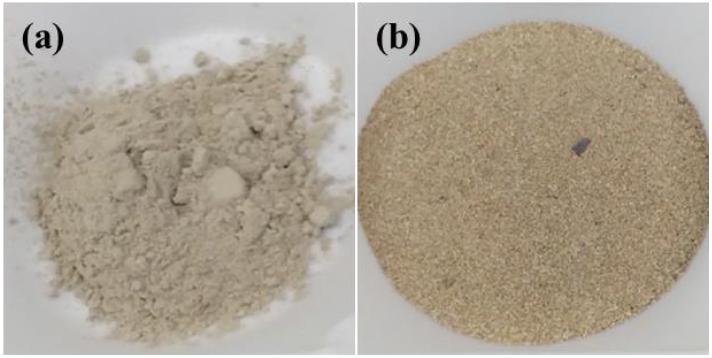
When SRF is burned in a bottom boiler, most of the unburned material is caught in the flue gas and captured as fly ash. Bottom ash is an incombustible byproduct that is collected from the bottom of the furnaces that burn SRF for generating steam. Therefore, fly ash and bottom ash are quite different physically and chemically. The fly ash and the bottom ash used in the study are shown in
Figure 3.
The fly ash was composed of fine particles, while the bottom ash was coarse and granular. The color of the bottom ash was dark, dull brown while the color of the fly ash was light brown.
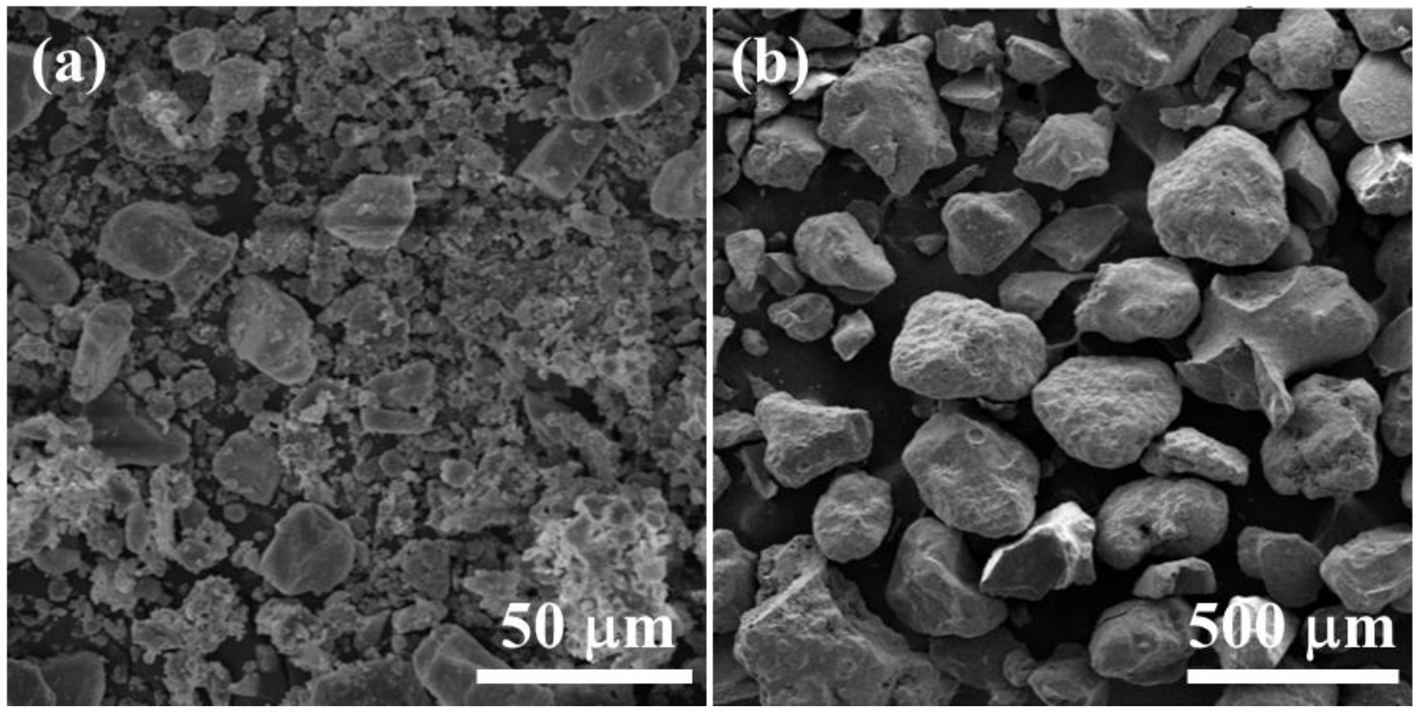
Figure 4 shows the morphologies of the fly ash and the bottom ash. The microstructure of the bottom ash (
Figure 4b) had a much larger particle size compared to fly ash, which was about the size of sand but was more porous. As shown in
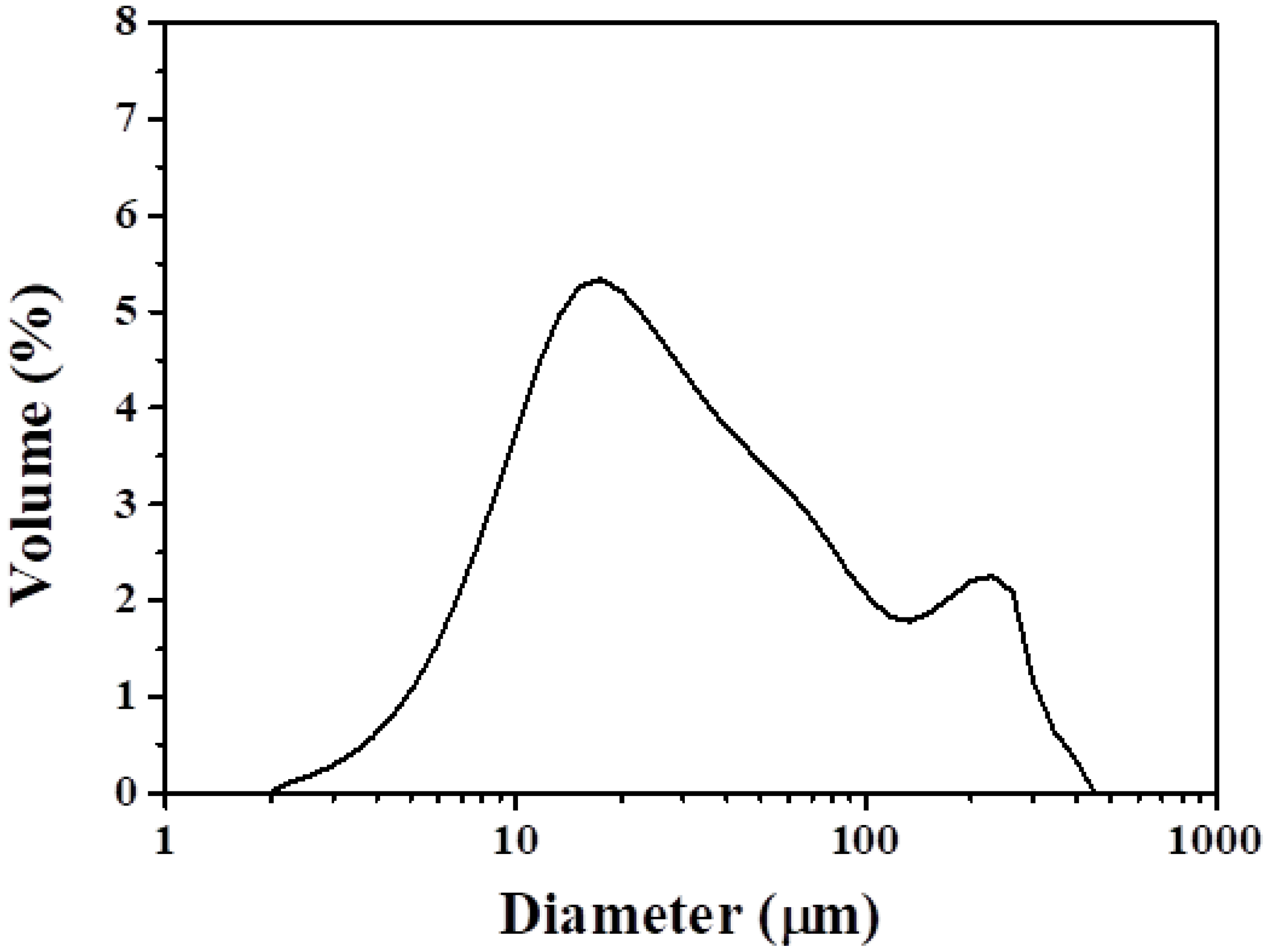
Figure 5, the particle size of the fly ash was between 2 and 130 µm, with D50 (medium diameter) of 25 µm, D10 of 7 µm and D90 of 160 µm.
Table 1 shows the results of X-ray fluorescence analysis of the fly ash and bottom ash. Concentration of the major elements in the fly ash was given in the form of oxides by XRF. The chemical compositions of the fly ash showed that SiO
2, Al
2O
3, Fe
2O
3, CaO, and Na
2O were the main oxides. On the other hand, the major chemical composition of the bottom ash was SiO
2. Lead and copper were the most common heavy metals in both ashes (
Table 2).
The content of CaO (17.1%) in the fly ash was much higher than that in the bottom ash (7.27%). Therefore, the fly ash, which has high calcium-based contents, was selected for CO2 capture.
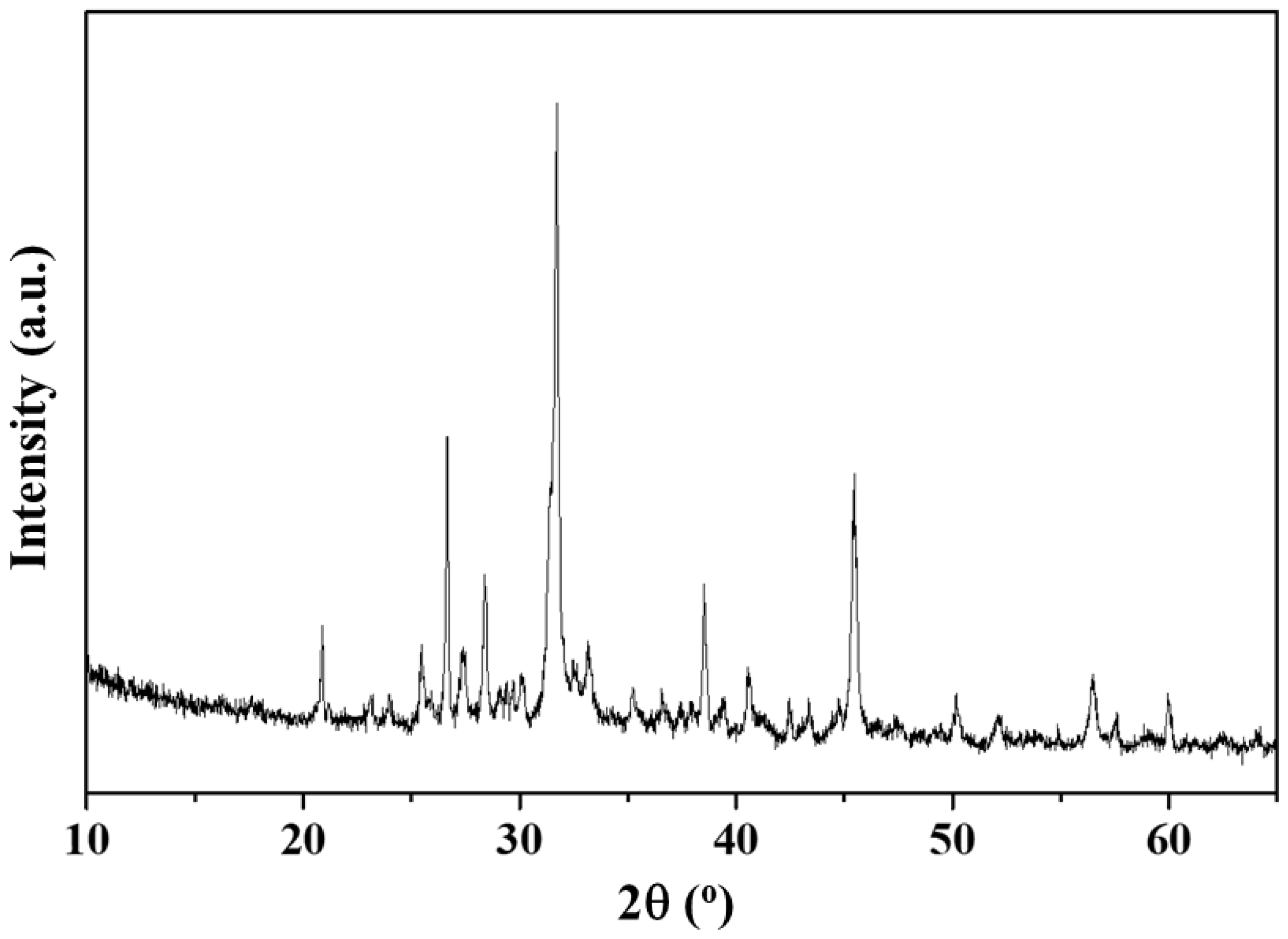
Figure 6 shows the crystal structure of the fly ash. The XRD pattern in
Figure 6 confirms the formation of composite powders with mixed crystal structures consisting of periclase (MgO), lime (CaO), calcite (CaCO
3), anhydrite (CaSO
4), quartz (SiO
2), mullite (3Al
2O
3-2SiO
2), hematite (Fe
2O
3), gehlenite (Ca
2Al[AlSiO
7]), halite (NaCl), and sylvite (KCl). The calcium-based materials such as calcite, anhydrite, and gehlenite could be prepared by a high temperature combustion. By using the relative intensity ratio (RIR) technique from the XRD we found that the weight percentage of the periclase, lime, calcite, anhydrite, quartz, mullite, hematite, gehlenite, halite, and sylvite were 0.89, 0.40, 3.02, 7.57, 12.78, 0.54, 2.27, 24.58, 42.46, and 5.48%, respectively (
Table 3).
Among the above materials, calcium-based materials (lime, anhydrite, and gehlenite) can react with CO2:
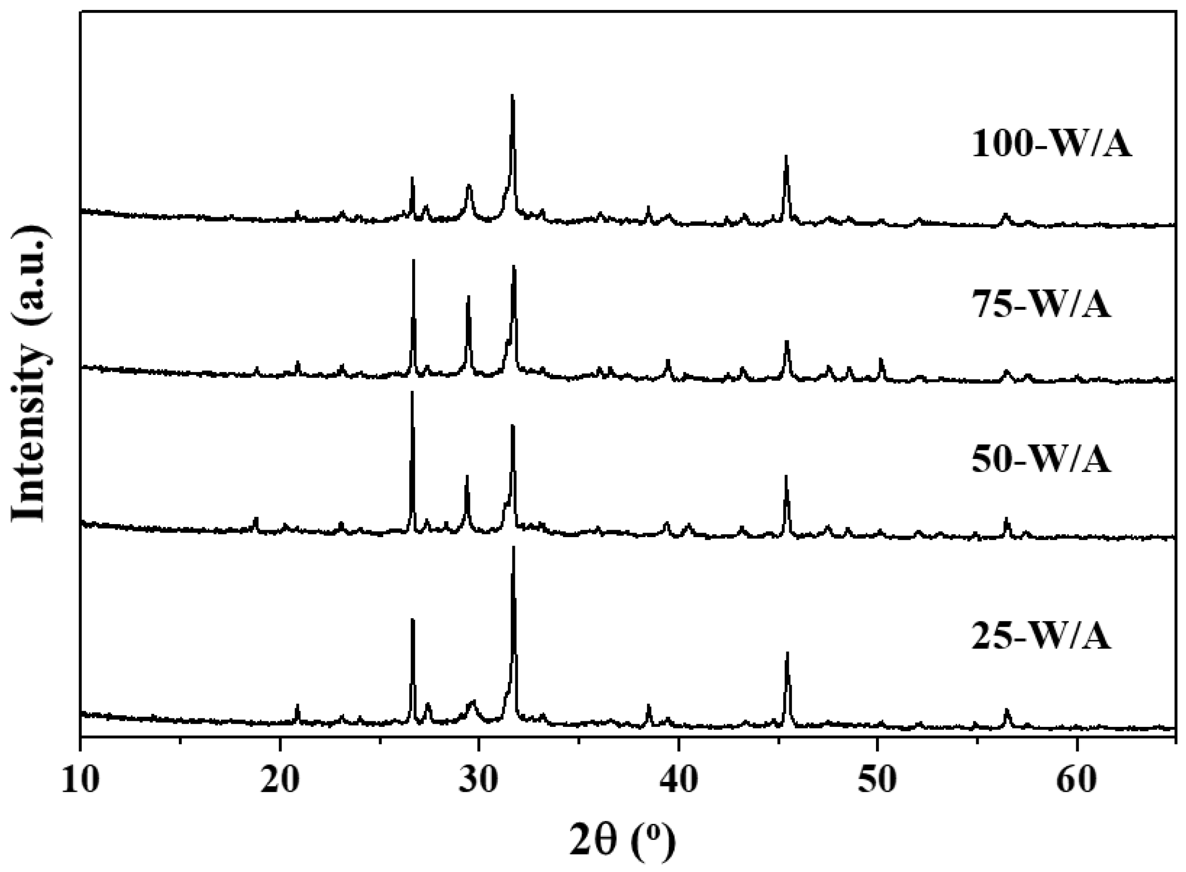
To investigate the effect of the amount of moisture on the performance of fly ash for CO2 capture, reaction with CO2 was conducted with the following amounts of water: 25 (25-W/A), 50 (50-W/A), 75 (75-W/A), and 100% (100-W/A). The CO2 concentration and reaction time were fixed at 100% and 60 min, respectively.
Figure 7 and
Table 4 show the crystal structure of the fly ash after CO
2 capture using different amounts of moisture and materials by using the relative intensity ratio (RIR) technique from the XRD. The CaCO
3 components of the 25-W/A, 50-W/A, 75-W/A, and 100-W/A were 14.13, 21.31, 26.16, and 21.98%, respectively. The amount of CaCO
3 increased with increasing the amount of water. This suggests that the presence of water played an essential role in hydrating the calcium-based materials to form calcium hydroxide, which then sequestrated carbon by forming calcium carbonate. Notably, the amount of CaCO
3 increased from 3.02 to 26.16% when the ratio of the ash-to-water was 1:0.75. The results showed that fly ash of 100 g from a SRF fired power plant captured CO
2 of 10.17 g. However, when the ratio of the ash-to-water was 1:1, the amount of CaCO
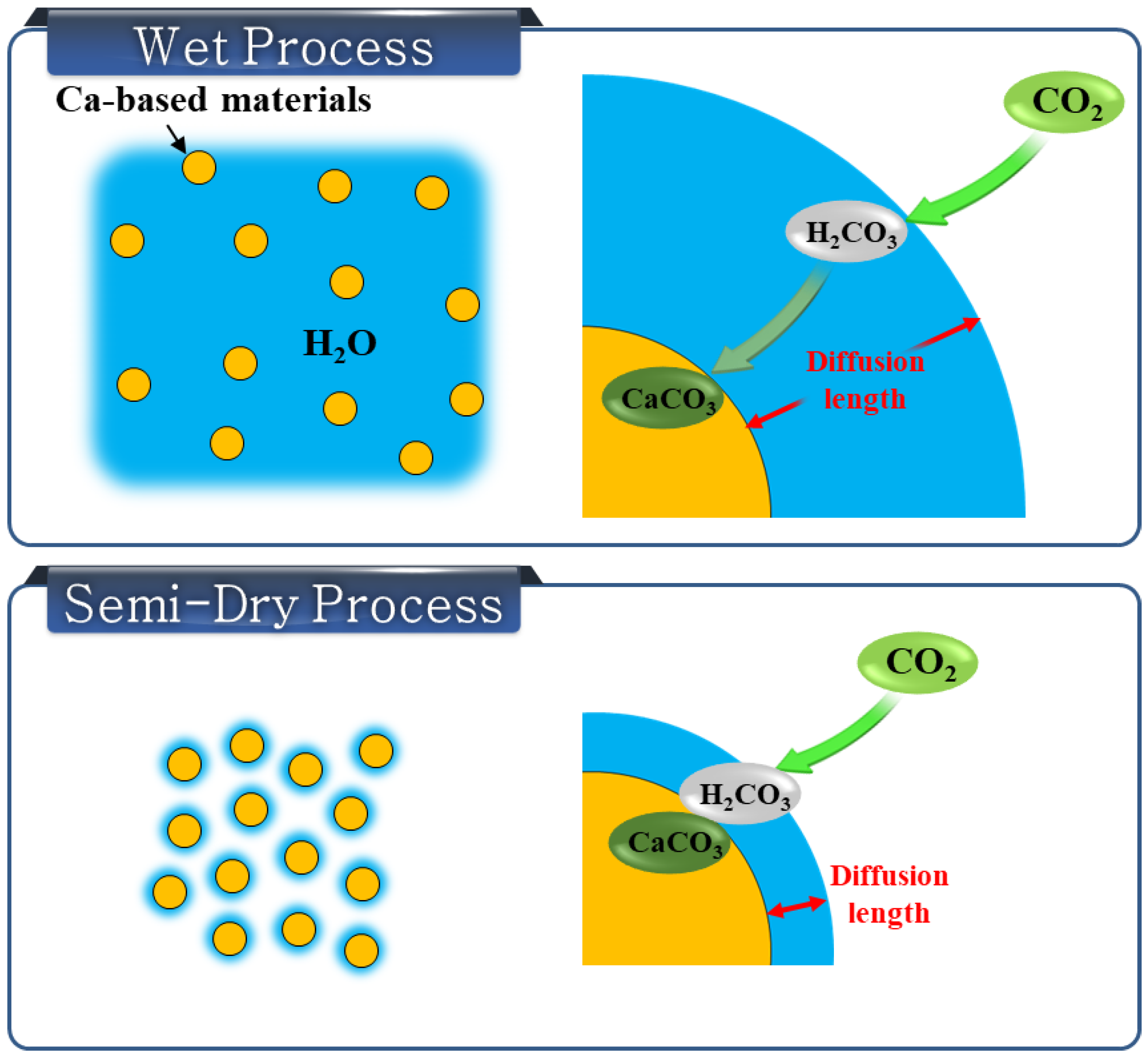
3 decreased. CO
2 in gaseous phase does not react with calcium-based materials; it has to dissolve in the water first to form carbonic acid (H
2CO
3) [
22]. As shown in
Figure 8, the diffusion length of the H
2CO
3 from the outside of the water to the calcium-based materials increased with the increasing amount of water. Therefore, the fly ash with too much water reacted slowly with CO
2.
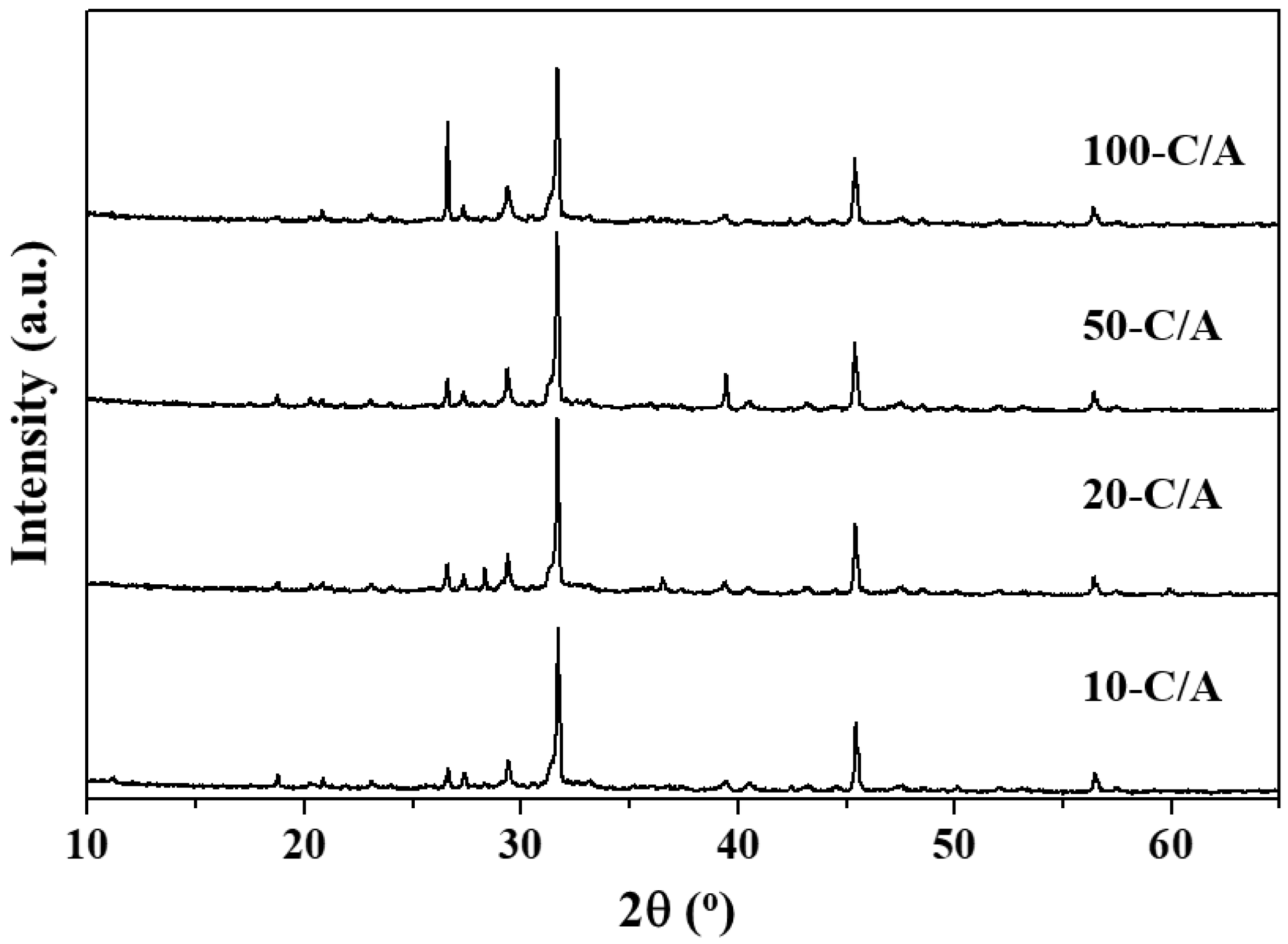
To investigate the properties of the fly ash with a small amount of water in the environments with low CO2 concentrations, CO2 captures were conducted at CO2 concentrations of 10 (10-C/A), 20 (20-C/A), 50 (50-C/A), and 100% (100-C/A). The moisture content and reaction time were fixed at 20% and 10 min, respectively.
Figure 9 and
Table 5 show the crystal structure of the fly ash after CO
2 capture using different concentrations of CO
2 and the amount of materials by using the relative intensity ratio (RIR) technique from the XRD. The CaCO
3 components of the 10-C/A, 20-C/A, 50-C/A, and 100-C/A were 15.21, 19.46, 19.86, and 21.98%, respectively. As shown in
Table 5, the CaCO
3 component stabilized at CO
2 concentration of 20%. This result indicates that the semi-dry process can be applied to the power plant without a CO
2 concentration process.
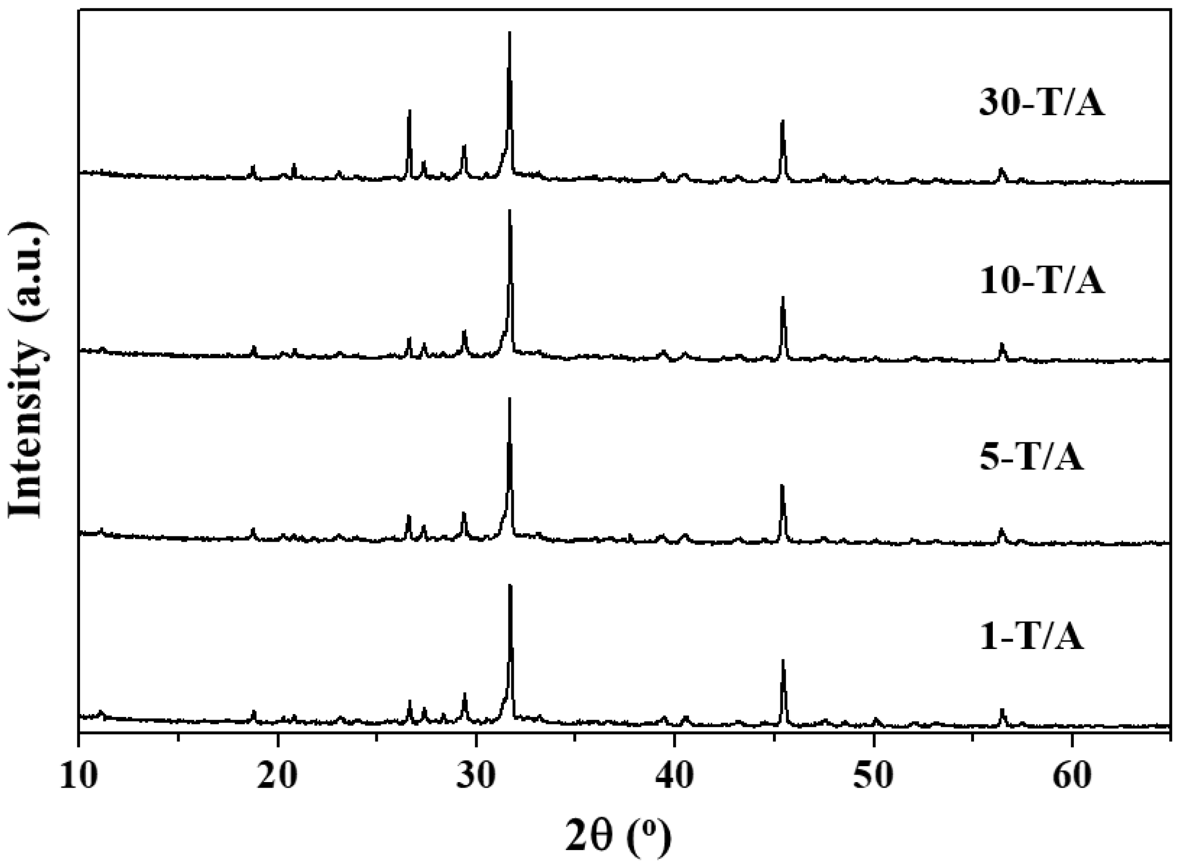
Figure 10 and
Table 6 show the crystal structure of the fly ash after CO
2 capture in a reaction time of 1 (1-T/A), 5 (5-T/A), 10 (10-T/A), and 30 min (30-T/A), and the amount of materials. The CaCO
3 component of the 1-T/A, 5-T/A, 10-T/A, and 30-T/A was 16.26, 15.16, 15.21, and 16.72%, respectively. As shown in
Table 6, the carbonation performed well despite the short reaction time of 1 minute. This result indicates that the semi-dry process can be designed as a continuous process to capture large scales of CO
2.


