Abstract
Providing support for deep soft rock roadways under dynamic pressure is a major technical challenge. In this study, the distribution characteristics of surrounding rock-bearing structure of such roadways were systematically examined using theoretical analysis and numerical simulation. Based on the control effect of different support methods on the surrounding rock-bearing structure; a reinforcement scheme for deep dynamic soft rock roadway was proposed and applied. The results indicate that: (1) by increasing the supporting strength of the internal bearing structure, cohesion, and internal friction angle of the surrounding rock, and by reducing the influence of mining, making the external bearing structure close to the roadway and reducing the thickness of the bearing structure, can improve the bearing capacity of the shallow surrounding rock in the roadway; (2) under the conditions of dynamic load and creep of the surrounding rock; the deformation of the rock increases significantly; external bearing structure is far away from the roadway, and thickness of the bearing structure increases; anchor cable support and floor pressure relief effect better control over the roof and the roadside deformation and floor heave, respectively; and the thickness of the corresponding external bearing structure is reduced by 30.84% and 41.50%, respectively; and (3) based on the application, the zonal reinforcement scheme of “fix cable to shed, floor pressure relief, deep-shallow composite grouting” is proposed and put into practice, with good results. The results of this study can provide theoretical support and reference for the determination of supporting parameters in deep roadways.
1. Introduction
As the depth of coal mining increases year by year, the difficulty of ensuring the stability of rocks that surround roadways in the face of complex geological conditions and mechanical environment poses a serious challenge to the safe and efficient mining of deep coal resources [1]. In view of the high ground pressure, considerable disturbances, and plastic softening of rock mass in the deep roadway, several studies have been conducted on the control of surrounding rock in deep roadways focusing on three main areas: change characteristics of brittleness to ductility of deep rock mass, bearing mechanism of the rock, and the control technology used.
(1) Experimental studies have been conducted on the process of brittle–ductile transformation of deep rock mass, which laid a foundation for the study of control strategies for rocks surrounding deep roadways. He et al. [2] put forward that deep rock masses have aging characteristics and transforms from brittleness to ductility under high confining pressure; Xu et al. [3] studied the microscopic mechanism of brittle to plastic transformation of granite under high temperature, considering the characteristics of the high-temperature environment surrounding the deep rock mass; Gowd et al. [4] and Fredrich et al. [5] carried out triaxial compression tests on rocks and obtained the critical confining pressure value of the brittle–ductile transformation in rocks; Cao et al. [6] and Zhao et al. [7] established a statistical constitutive model of rock damage which can reflect the brittle–ductile characteristics and their mutual transformation characteristics based on the statistical damage theory and triaxial test curves.
(2) Theoretical studies have been carried out on the bearing mechanism of rocks surrounding roadways and have defined the main objects of roadway support. Based on the analysis of the plastic zone theory, Zhang et al. [8] considered that the range and shape of the plastic zone of the surrounding rock is the theoretical basis for the quantitative design of the supporting structure, and proposed a support scheme for the weakly cemented soft rock roadway; Zhang et al. [9] studied the distribution characteristics of surrounding rock loose circle in weak roadway, and guided the design of the supporting parameters; Zhu et al. [10] studied the coordination effect of the primary and secondary bearing areas of the surrounding rock, and concluded that the surrounding rock compression domain is the main bearing area; Nazimko et al. [11] studied the failure process of the surrounding rock in roadways under deep dynamic pressure by actual measurement. It was found that there were extruding and compressive zones in surrounding rock, and the compressive zone increased the stability of the surrounding rock; Kang [12] put forward the key circle theory of rocks surrounding roadways, and expounded the influencing factors of the key bearing circle and its distribution characteristics; Zhang et al. [13] studied the bearing mechanism of double bearing structures in deep soft rock roadways; considering the rock surrounding a broken roadway as a small bearing structure and the deep surrounding rock as a large bearing structure, Yang et al. [14] proposed the superimposed coupling support technology for large and small bearing structures; Wang et al. [15] and Yang et al. [16] analyzed the bearing mechanism of rock surrounding roadways from the stress distribution.
(3) Based on the bearing mechanism of the rock, support technology for deep roadways was developed and implemented. Kang et al. [17,18] divided the relevant roadways in into five types, and concluded that rock bolting had become me the primary form of roadway support in Chinese coal mines; Zhao et al. [19] proposed a U-shaped steel closed support with an inverted U-shaped steel arch in the floor for improving the support effect of the surrounding rock in deep roadway; Skrzypkowski, K. [20] considered that the arched yielding support plays a decisive role in stability under dynamic loads in the deep mines and a new design of arch yielding support was proposed, in addition, in the conditions of the roof, made of rocks prone to sagging, an yielding rock bolt support be used [21]; based on the “bolt-mesh-anchor-shed” combined support technology [22,23,24], Li et al. [25] and Xie et al. [26] proposed a double anchor control technology and high pre-stressed anchor cable truss support, respectively.
However, the factors that influence the stability of the rock that surrounds roadways are complex, and it is necessary to carry out supporting research according to the specific geological conditions of the mine. At the same time, few studies delineate the interaction between the support structure and bearing area, and available analyses of bearing mechanism of surrounding rock are insufficient to guide support design quantitatively. Based on the bearing structure of the rock surrounding the roadways, this paper analyzes the factors that influence the stability of the surrounding rock in deep soft rock roadways under dynamic pressure, and proposes the coupling reinforcement support scheme. The results can provide references for surrounding rock control in deep dynamic soft rock roadways.
2. Microstructure and Bearing Structure of Surrounding Rock in Deep Roadways
2.1. Microstructure of Roadway-Surrounding Rock
The surrounding rock of deep roadways in Middle Eastern China is mainly composed of sandstone and mudstone. Strength testing of typical rock samples (sandstone, mudstone, argillaceous sandstone) was carried out by the research group in the mine above 800 m. The results show that the uniaxial compressive strength of sandstone, mudstone, and argillaceous sandstone are 8.59 MPa, 3.34 MPa, and 6.82 MPa respectively, and the rock mass strength is low. Scanning electron microscopy (SEM) is used to scan sandstone specimens (Figure 1).
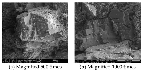
Figure 1.
The SEM photos of the sandstone micro-characteristics at different magnifications.
The results show that the sandstone microfracture is more developed and the integrity is destroyed, resulting in the decrease in sandstone strength. The surrounding rock of the deep roadway has the characteristics of low strength and microfracture development.
2.2. Internal and External Bearing Structures and Distribution Characteristics of Surrounding Rock in Deep Roadway Under Dynamic Pressure Non-Uniform Stress Field
After roadway excavation, stress in the surrounding rock is redistributed. There is a stress concentration in the surrounding rock at a certain distance from the roadway, and most of the stress is borne there. The coal and rock mass in the elastic–plastic zone near the peak stress region constitutes the main bearing structure or the external bearing structure. The inner bearing structure is formed at the edge of the roadway with the roadway supporting structure including the anchoring body, grouting body, and steel shed. For the deep roadway, the contradiction between the high stress and low strength of the surrounding rock leads to rapid deterioration of the surrounding rock after excavation; the rock can be divided into the broken zone, plastic zone, and elastic zone from the inside to the outside. As shown in Figure 2, R0 is the roadway radius; Rs is the broken zone radius; Ri is the internal bearing structure radius; Rp is the plastic zone radius; Rbi and Rb0 are the internal and external radii of the external bearing structure, respectively.

Figure 2.
Schematic diagram of the internal and external bearing structure of the deep roadway.
If the support strength of the deep roadway is insufficient after excavation, the crushing zone and plastic zone of the surrounding rock expand continuously, causing the external bearing structure to move out, thereby making it difficult to maintain the roadway, and posing safety risks. Based on the theory of elastic–plastic mechanics, this work analyzes the distribution characteristics and influencing factors of the inner and external bearing structure of the surrounding rock in a deep circular roadway under the action of a non-uniform stress field under dynamic pressure, which can provide a basis for roadway support design.
2.2.1. Elastic Zone Stress Field
The stress distribution in a circular roadway under a non-uniform stress field can be divided into two conditions: uniform compression, and bilateral compression and bilateral tension. As shown in Figure 3, P1 = (1 + λ) γH/2, P2 = (1 − λ) γH/2, λ is side pressure coefficient, γ is overburden density, H is overburden thickness; R is a radius much larger than Rp. For a roadway under dynamic pressure, P1 = (K + λ)γH/2, P2 = (K − λ)γH/2, where K is the dynamic load coefficient.
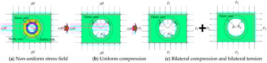
Figure 3.
Stress decomposition of circular roadway under non-uniform stress field.
Based on the Lame solution and the theories of elastic mechanics, the stresses in the roadway rock surrounding can be obtained under two stress fields as shown in Figure 3b,c. Therefore, the stress in the elastic zone of the circular roadway rock surrounding under non-uniform stress field can be obtained by the stress superposition under the above two stress fields as Equations (1) and (2).
where σre and σθe are the radial stress and tangential stress in the elastic zone, respectively, at any point under non-uniform stress field; r is polar radius, θ is the polar angle, and σRp is the stress at the interface of the elastic–plastic zone.
At the elastic–plastic interface (r = Rp), the Mohr–Coulomb yielding criteria (Equation (3)) is satisfied, and σRp (Equation (4)) can be obtained.
where C, φ in the equation are rock mass the cohesion and internal friction angle, respectively.
2.2.2. Stress Fields in Plastic and Broken Zones
According to the stress equilibrium equation and limit equilibrium condition in the plastic zone, the equations of stress in the plastic zone are shown in Equations (5) and (6).
where σrp and σθp are the radial stress and tangential stress in the plastic zone, respectively.
Based on the limit state Equation of the Coulomb criterion in the broken zone, the equations of stress in the broken zone are shown in Equations (7) and (8).
where σrs and σθs are the radial stress and tangential stress in the broken zone, respectively; is residual compressive strength of surrounding rock, , and is internal friction angle of broken rock mass.
The radial stress is continuous at the interface between the broken zone and the plastic zone, and Equation (9) can be deduced according to Equations (5) and (7).
Equation (10) can be known from the plastic flow rule as well as the geometry.
Among Equation (10), G = (1 + μ) [2P1(1 − μ) − σRp + 4P2(1 − μ) cos2θ]/E, Q is the softening modulus of rock mass strength, and η is the dilatancy gradient of surrounding rock in plastic softening area.
The Equations (11) and (12) can be obtained from Equations (9) and (10).
2.2.3. Distribution Characteristics of External Bearing Structure
Assuming that the external bearing structure bears half of the load that generates stress in the rock, that is Equation (13). At the same time, where the tangential stress of the plastic zone is 1.1 times the original rock stress, that is the inner radius of the external bearing structure. Therefore, the inner and external radius of the external bearing structure can be obtained by Equations (14) and (15).
where Rd is the radius in the elevated stress area.
The internal and external radius of the external bearing structure (Rbi,Rb0) can be obtained from Equation (2), Equation (4), and Equations (11)–(15).
Figure 4 is the change curves of broken zone radius Rs, plastic zone radius Rp, external radius of external bearing structure Rb0, external bearing structure thickness tb, and stress concentration factor k1 of surrounding rock of the roadway under different support strengths (Pi), mechanical properties of surrounding rock (cohesion C, internal friction angle φ), and dynamic load coefficient (K).
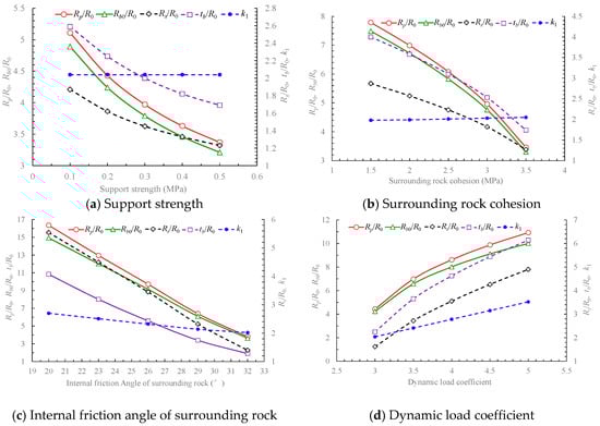
Figure 4.
Change curves of bearing structure parameters under different conditions.
Figure 4 indicates that:
- With the increase in surrounding rock cohesion and internal friction angle, the ratio of the width of the broken zone and plastic zone to roadway radius is gradually reduced, and the external bearing structure is close to the roadway while its thickness is reduced. It indicates that for the rock mass with higher strength, the plastic zone of the rock surrounding the roadway is smaller, and the shallow surrounding rock plays the main bearing role. The roadway is easy to maintain.
- When the roadway is affected by mining, with the increase in the dynamic load coefficient, the ratio of broken zone and plastic zone dimensions to roadway radius increases gradually, the external bearing structure of the rock surrounding the roadway shifts to the deep part of the surrounding rock, and the thickness of the load-bearing structure increases. It shows that when affected by mining, the plastic zone of the rock is larger, and the deep surrounding rock plays the main bearing role. The maintenance of the roadway is difficult.
- With the development of the broken zone and plastic zone of the surrounding rock, the external bearing structure is far away from the roadway, and the roadway is difficult to maintain. Therefore, the main idea of ensuring the stability of the surrounding rock is improving the bearing capacity of the shallow surrounding rock and controlling the position of the external bearing structure. In combination with the change curves of the bearing structure parameters, it can improve the stability of the rock surrounding the roadway by increasing the support strength of the internal bearing structure, cohesion, and internal friction angle of surrounding rock as well as reducing the degree of mining influence.
3. Control Mechanism of Surrounding Rock-Bearing Structure for Deep Soft Rock Roadway Under Dynamic Pressure
In addition to the influence of in situ stress, the stability of surrounding rock in deep roadway is also subject to strong disturbances and plastic softening of the rock mass. To clarify the bearing mechanism of the surrounding rock for deep soft rock roadway under dynamic pressure, based on the production geological conditions in the Pingdingshan coal industry group, the change characteristic of surrounding rock-bearing structure under different conditions is simulated using the Fast Lagrangian Analysis of Continua 3D software (FLAC3D version 5.0, Itasca Consulting Group, Inc., Minneapolis, MN, USA). The control effects exerted by different support methods on the surrounding rock are analyzed in this section.
3.1. Change Characteristics of External Bearing Structure of Roadway-Surrounding Rock
According to the scheme in Table 1, the corresponding numerical simulation models are established to analyze the change characteristic of the external bearing structure of rock surrounding the roadway under different conditions. The roadway is arranged in argillaceous sandstone, the roof is sandstone, the floor is mudstone, and the dip angle of rock stratum is 0°.

Table 1.
Numerical simulation scheme for change characteristic of bearing structure of rock surrounding a roadway.
The shape of the roadway section is a straight wall arch, and the width and height dimensions of is 5 m × 3.5 m, and the buried depth is 900 m. The lateral and bottom boundary displacement are constrained, and the upper boundary represents the free surface. A constitutive model is selected, and the stress boundary is assigned according to the simulation scheme, and the coefficient of horizontal pressure was 0.5.
According to Section 2.2, the area of external bearing structure is the area where the tangential stress of surrounding rock rises, and the tangential stress of roadway side is the vertical stress. Therefore, the location of the external bearing structure and the width of the external bearing structure at the roadway side are determined by the peak tangential stress and the vertical stress of the surrounding rock, respectively. Figure 5 is the distribution of tangential stress of the surrounding rock under different conditions. The location of the external bearing structure is determined by the peak value of tangential stress. Figure 6 shows the correlation curves between the external bearing structure parameters and deformation of the surrounding rock.
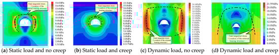
Figure 5.
The distribution of tangential stress and external bearing structure of surrounding rock under different conditions.
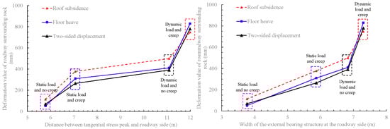
Figure 6.
Correlation curves between external bearing structure parameters and surrounding rock deformation.
Figure 6 shows that the deformation of surrounding rock under dynamic load and creep is significantly higher than that under static load without creep, the external bearing structure of surrounding rock is far away from the roadway, and the thickness of external bearing structure increases. When the roadway is in a static load state and has no creep, the deformation associated with roof subsidence, floor heave, and the two-sided displacement are 114.5 mm, 51.52 mm and 69.09 mm, respectively. At this time, the tangential stress peak of the surrounding rock at the roadway side is 5.78 m away from the roadway, and the thickness of the external bearing structure is 3.77 m. When the roadway is subjected to dynamic load and creep occurs, the deformation of the surrounding rock of the roadway increases about 11 times. The peak of the tangential stress of the surrounding rock at the roadway side is 11.99 m away from the roadway and the thickness of external bearing structure is 7.30 m, which increases 2.07 and 1.94 times, respectively.
3.2. Control Effect of Roadway-Surrounding Rock-Bearing Structure Under Different Support Methods
To further clarify the control mechanism of rock that surrounds roadways under the influence of different support methods, this paper simulates the control effects of different support methods such as shed support, floor pressure relief, anchor cable support, and grouting reinforcement on the surrounding rock-bearing structure. The simulation scheme is shown in Figure 7. The steel shed is made of 36 U-shaped steel, with an elastic modulus of 210 GPa and a tensile strength of 530 MPa. Pretension of anchor cable is 30 kN and the length of anchor cable is 6.5 m. According to the field test, the uniaxial compressive of surrounding rock in the grouting area is 8.87 MPa, and the tensile strength is 1.13 MPa.
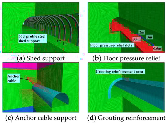
Figure 7.
Simulation scheme of different support methods.
According to the above analysis, increasing the support strength of the internal load-bearing structure, cohesion, and internal friction angle of the surrounding rock, and reducing the dynamic load coefficient can make the external bearing structure close to the roadway and the thickness of the bearing structure decreases, while the bearing capacity of the surrounding rock in the shallow roadway increases. At the same time, when the surrounding rock deformation of the roadway is large, the external bearing structure is far away from the roadway and the thickness of the bearing structure increases. Therefore, the thickness of the external bearing structure is used as the evaluation index of the control effect, and the simulation result is shown in Figure 8.
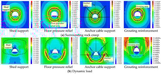
Figure 8.
Distribution of roadway-surrounding rock external bearing structure with different support methods.
The distribution of the thickness of the external bearing structure under different support methods is shown in Figure 9.
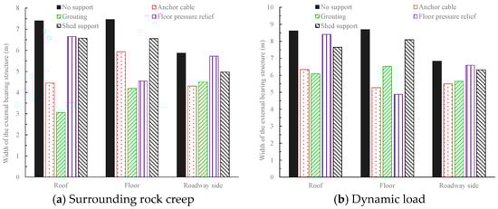
Figure 9.
Thickness distribution of external bearing structure under different support methods.
Figure 9 shows that: (1) under the condition of creep in the rock that surrounds the roadways, the anchor cable support can effectively reduce the thickness of the external bearing structure at the roof and the side, and the thicknesses are 39.81% and 26.63% less than that without the support, respectively. In addition, when the pressure on the roadway floor is relieved, the thickness of the external bearing structure at the floor is reduced by 39.14%. (2) Under the dynamic load, when the anchor cable is used, the thickness of the external bearing structure is reduced by an average of 28.45%. When the floor is relieved, the thickness of the external bearing structure at the floor is reduced by 43.85%. (3) Under the conditions of creep and dynamic load, the thickness of the external bearing structure decreased by 41.93% and 23.88%, respectively, with the grouting reinforcement, and the thickness of the external bearing structure decreased by 12.87% and 8.52% with the shed support. It shows that grouting reinforcement has a good control effect under the condition of surrounding rock creep, and the support effect of the shed support is poor.
In conclusion, the deformation of rock surrounding the roadway increases significantly under the conditions of creep and dynamic load, and the external bearing structure is far away from the roadway and the thickness increases. In the process of supporting the deep, soft surrounding rock, the thickness of the external bearing structure or the thickness of the plastic zone of the surrounding rock can be reduced to improve the bearing capacity of the surrounding rock using anchor cable support and floor pressure relief. Anchor cable support can effectively control the deformation of the roof and the sides of the roadway. Pressure relief of the floor is effective in controlling the deformation of the floor heave. Grouting reinforcement can be used to control the deformation of the surrounding rock when it is prone to creep or fracture.
4. Reinforcement Support Technology for Deep Soft Rock Roadway Under Dynamic Pressure and Its Application
According to the control mechanism of the surrounding rock-bearing structure, the support design of the main inclined shaft is quantitatively analyzed for the No. 4 coal mine in Pingdingshan coal industry group. The coupling reinforcement support scheme of the deep dynamic soft rock roadway has been proposed.
4.1. Engineering Situation
The main inclined shaft of the No.4 coal mine is 1200 m in length, with a slope of 19°20′. It obliquely penetrates three groups of coal seams, namely the D, E, and F coal seams, with a depth of 700 m~900 m and a design section of 27.78 m2. It is responsible for the main pedestrian and ventilation tasks at the second and third levels. The layout of the main inclined shaft layout space is shown in Figure 10. Due to the development needs of mine, after the construction of the main inclined shaft, the F15 coal seam is mined first, followed by the E8 coal seam, and finally, the F16 coal seam.
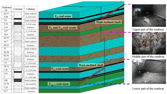
Figure 10.
Engineering geology of the main inclined shaft.
The surrounding rock of the main inclined shaft is mainly composed of sandy mudstone and mudstone, which accounts for 73.17% of the total length of the roadway. The roadway was originally supported by the combination of “bolt-mesh-anchor-shed”, but control effect was not good. The length of large deformation roadway is 1100 m.
4.2. Control Analysis of Bearing Structure of Rock Surrounding the Roadway
The surrounding rock of the main inclined shaft is mainly composed of sandy mudstone and mudstone, which easily disintegrate, soften, and expand when meeting with water, and the strength of surrounding rock is reduced. Some sections pass through the fault, the surrounding rock is broken, and the entire bearing capacity is reduced. Meanwhile, the roadway is arranged in the protection coal pillars of district dip. The surrounding rock has large in situ stress, stress concentration, and is affected by the mining of the two wings working faces. The main inclined shaft is a typical deep dynamic soft rock roadway.
Combined with the variation characteristics of the surrounding rock stress and the geological conditions when the coal seam groups are mined, the roadway can be divided into three areas: the upper part of the main inclined shaft (range of 0~50 m under the E8 coal seam floor) is greatly affected by the dynamic load, mainly the deformation of the roof and floor; the middle part of the main inclined shaft (range of 50~120 m under the E8 coal seam floor) is affected by the mining of the working face and the creep of the surrounding rock, the roof subsides, and the top corner of roadway is severely compression damaged. The lower part of the main inclined shaft (range of 120~170 m under the E8 coal seam floor) is greatly affected by the creep of the surrounding rock, the floor heave is serious, and the roof and side are intact.
The middle part of the main inclined shaft is selected to analyze the bearing structure characteristics. The roadway width is 5 m, the compressive strength of surrounding rock is 3.5 MPa, the internal friction angle and cohesion are 30.57° and 3.2 MPa respectively, the rock mass strength softening modulus is 0.05 GPa, and the expansion gradient of plastic softening zone in the surrounding rock is 1.5, when the dynamic load coefficient and the lateral pressure coefficient are 3 and 1.2 respectively, the bearing structure of the roadway is shown in Figure 11a. At this time, the thickness of surrounding rock broken zone at the roadway side is 0.48 m, the thickness of plastic zone is 5.51 m, the inner radius of the external bearing structure is 0.78 m from the roadway, the external radius is 7.33 m, and the thickness of external bearing structure is 6.55 m.
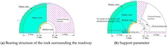
Figure 11.
Schematic of bearing structure control of rock surrounding the roadway.
Based on the analysis in Section 3.2, for the roadway under creep and dynamic load, the anchor cable support and grouting reinforcement can effectively reduce the distance to the roadway and thickness of the external bearing structure at the roof and side, and control the surrounding rock deformation of corresponding positions. The floor pressure relief has an obvious effect in controlling the floor heave. According to the deformation characteristics and key influencing factors of surrounding rock in different areas of the main inclined shaft, the following reinforcement measures and supporting parameters are proposed (Figure 11b):
In the upper- and middle-part areas of the roadway, the anchor cable is used to control the roof subsidence. The anchor cable needs to be anchored in the elastic zone to prevent the external bearing structure from moving outward. The length of the anchor cable should not be less than 5.99 m.
Implement deep-shallow composite grouting in the surrounding rock fragmentation area of the roadway to improve the bearing capacity of the internal and external bearing structures. When the exposed length of grouting bolt is 0.35 m, the length of the shallow grouting bolt is not less than 0.83 m. The length of the deep grouting bolt is not less than 2.13 m if the deep grouting range is calculated based on 1 m depth of the external bearing structure.
The floor pressure relief in the upper and lower areas of the roadway can release the broken deformation energy and reduce the floor heave in a controlled manner.
4.3. Zone Reinforcement Support Scheme and Field Application
4.3.1. Zone Reinforcement Support Scheme
According to the analysis of reinforcement countermeasures, the main inclined shaft division reinforcement support scheme of “cable fix to shed, floor pressure relief, deep-shallow composite grouting” is proposed. The support parameters are determined according to the analysis of internal and external bearing structures. The specific scheme is shown in Figure 12.
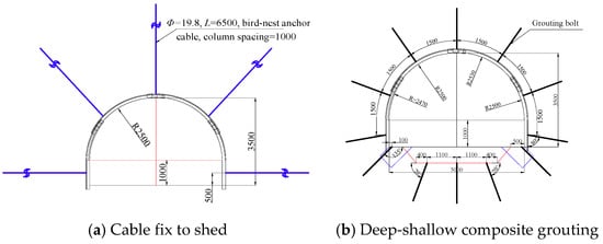
Figure 12.
Scheme of main inclined shaft support reinforcement (unit: mm).
“Cable fix to shed” is the use of a U-shaped steel structure to fix the anchor cable and the steel shed together. Shed is equivalent to the anchor cable tray. The tension of the anchor cable is evenly transmitted to the rock mass anchored by increasing the rigidity and resistance of the tray. The cable adopts the bird-nest anchor cable, the specification is Φ 19.8 mm × L 6500 mm, the column spacing is 1000 mm, and the anchor cable tray uses 36 U-shaped steel fixtures.
“Deep-shallow composite grouting” means that whole shallow grouting section is first implemented, deep hole grouting reinforcement is applied subsequently after the shallow surrounding rock is effectively reinforced. Shallow grouting bolt specification is Φ 26 mm × L 1500 mm, deep grouting bolt is Φ 26 mm × L 2500 mm, and the row and column spacing is 1500 mm × 2000 mm.
4.3.2. Field Application
Construction is carried out according to the reinforcement support scheme, and the “cross measurement method” is used to monitor the displacement of the surface surrounding rock of the main inclined shaft for six months. In the first 60 days, anchor fix shed reinforcement and initial shotcrete were carried out. At the same time, pressure relief slots were excavated, and roadway floor cutting was carried out to ensure the roadway section shape; 60–90 days grouting bolts were installed, and shallow grouting was carried out; 90–120 days deep grouting and secondary shotcrete were implemented.
After construction, the shape of the roadway section is complete, the shed does not have obvious deformation (Figure 13a), and the displacement change curve of the roadway surface is shown in Figure 13b.
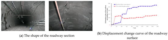
Figure 13.
Situation of rock surrounding the roadway after construction.
Figure 13 shows that due to the fixing cable and shed and enlargement in the first 60 days, the deformation of the rock surrounding the roadway fluctuates greatly. From 60 days, the deformation of the surrounding rock tends to be stable due to the reinforcement of “cable fix to shed, floor pressure relief”. The roof-to-floor convergence is 277 mm and the two-sided displacement is 135 mm. The control effect of the surrounding rock is good.
5. Conclusions
In view of the characteristics of high ground pressure, strong disturbance, and plastic softening of rock mass in deep roadways, this work studies the bearing mechanism and control technology of surrounding rock from the internal and external bearing structure of rock that surrounds roadways. The main conclusions are as follows:
(1) The distribution characteristics of the surrounding rock internal and external bearing structure for deep roadway under dynamic non-uniform stress field and its influencing factors were analyzed in theory. The stress distribution mechanical model of the rock surrounding the roadway was established. The calculation result shows that it can control the development of the broken zone and plastic zone of the rock surrounding the roadway, make the external bearing structure close to the roadway and reduce the thickness of the bearing structure through increasing the supporting strength of the internal bearing structure, cohesion, and internal friction angle of the surrounding rock and reducing the influence of mining. That can improve the bearing capacity of the shallow surrounding rock in the roadway and make the roadway easy to maintain.
(2) The deformation characteristics and control mechanism of surrounding rock in deep dynamic soft rock roadway were numerical simulated. Under the condition of dynamic load and creep, the deformation of rock surrounding the roadway is significantly higher than that without creep and under static load. The external bearing structure is far away from the roadway, the thickness of the bearing structure is increased, and the distance to the roadway and thickness of the external bearing structure are increased by 2.07 and 1.94 times, respectively. For the deep soft rock surrounding the roadway under dynamic load, anchor cable support and floor pressure relief have better control effects on the roof-side deformation and the floor heave respectively, and the thickness of the external bearing structure is reduced by 30.84% and 41.50% respectively. When the surrounding rock is prone to creep or fracture, grouting reinforcement can reduce the thickness of the external bearing structure by 41.93%, and it has a better control effect on the surrounding rock.
(3) In combination with field practice, the length of the anchor cable and the scope of surrounding rock grouting reinforcement are defined based on the distribution characteristics of the surrounding rock-bearing structure. The length of the anchor cable should not be less than 5.99 m, the lengths of shallow grouting bolt and deep grouting bolt should not be less than 0.83 m and 2.13 m, respectively. The zonal reinforcement scheme of the “cable fix to shed, floor pressure relief, deep-shallow composite grouting” is put forward and applied, which gave good results.
Author Contributions
All the authors contributed to publishing this paper. D.Q. prepared and edited the manuscript. X.W. and D.Z. participated in the data processing during the research process. X.C. was responsible for pictures drawing.
Funding
This study was funded by the Fundamental Research Funds for the Central Universities (No. 2018BSCXC32) and the Postgraduate Research & Practice Innovation Program of Jiangsu Province (No. KYCX18_1964).
Acknowledgments
The authors would like to thank the editor and the reviewers for their contributions on the paper.
Conflicts of Interest
The authors declare no conflict of interest.
References
- He, M.C. Rock mechanics and hazard control in deep mining engineering in China. In Proceedings of the 4th Asian Rock Mechanics Symposium, Singapore, 8–10 November 2006; World Scientific Publishing Co., Ltd.: Singapore, 2006; pp. 29–46. [Google Scholar]
- He, M.C.; Gong, W.L.; Li, D.J.; Zhai, H.M. Physical modeling of failure process of the excavation in horizontal strata based on IR thermography. Min. Sci. Technol. 2009, 19, 689–698. [Google Scholar] [CrossRef]
- Xu, X.L.; Kang, Z.X.; Ji, M.; Ge, W.X.; Chen, J. Research of microcosmic mechanism of brittle-plastic transition for granite under high temperature. Procedia Earth Planet. Sci. 2009, 1, 432–437. [Google Scholar]
- Gowd, T.N.; Rummel, F. Effect of confining pressure on the fracture behaviour of a porous rock. Int. J. Rock Mech. Min. Sci. Geomech. Abstr. 1980, 17, 225–229. [Google Scholar] [CrossRef]
- Fredrich, J.T.; Evans, B.; Wong, T.F. Effect of grain size on brittle and semibrittle strength: Implications for micromechanical modelling of failure in compression. J. Geophys. Res. Solid Earth 1990, 95, 10907–10920. [Google Scholar] [CrossRef]
- Cao, W.G.; Zhao, H.; Li, X.; Zhang, Y.J. Statistical damage model with strain softening and hardening for rocks under the influence of voids and volume changes. Can. Geotech. J. 2010, 47, 857–871. [Google Scholar] [CrossRef]
- Zhao, H.; Cao, W.G.; Li, X.; Zhang, L. Effect of volume changes on complete deformation behavior of rocks. J. Cent. South Univ. Technol. 2010, 17, 394–399. [Google Scholar] [CrossRef]
- Zhang, J.H.; Wang, L.G.; Li, Q.H.; Zhu, S.S. Plastic zone analysis and support optimization of shallow roadway with weakly cemented soft strata. Int. J. Min. Sci. Technol. 2015, 25, 395–400. [Google Scholar] [CrossRef]
- Zhang, X.D.; Feng, G.; Xu, J.L. The fractal characteristics of wall rock crack in the soft rock roadway and study on theory of loose ring. Adv. Mater. Res. 2012, 396, 2494–2498. [Google Scholar] [CrossRef]
- Wang, H.P.; Li, S.C.; Xue, J.H.; Li, J.M.; Zhang, Q.H.; Ma, Q.Y. Control methods of stability of zonal disintegration surrounding rock in deep rock roadway and its application. Rock Soil Mech. 2014, 35, 1957–1964. [Google Scholar]
- Nazimko, V.V.; Peng, S.S.; Lapteev, A.A.; Alexandrov, S.N.; Sazhnev, V.P. Damage mechanics around a tunnel due to incremental ground pressure. Int. J. Rock Mech. Min. Sci. 1997, 34, 222.e1–222.e14. [Google Scholar] [CrossRef]
- Kang, H.P. Analysis on load-bearing ring in surrounding rock of roadway. Rock Soil Mech. 1996, 17, 84–89. [Google Scholar]
- Zhang, F.J.; Liu, P.; Meng, X.R.; Gao, Z.N. Research of bearing mechanism of double support structure of deep soft rock roadway. Adv. Mater. Res. 2013, 734–737, 606–613. [Google Scholar] [CrossRef]
- Yang, R.S.; Li, Y.L.; Guo, D.M.; Yao, L.; Yang, T.M.; Li, T.B. Failure mechanism and control technology of water-immersed roadway in high-stress and soft rock in a deep mine. Int. J. Min. Sci. Technol. 2017, 27, 245–252. [Google Scholar] [CrossRef]
- Wang, X.F.; Wang, Y.; Zhang, D.S. Enhanced support technology for key area of the roadway in large inclined angle “three-soft” coal seam. J. Min. Saf. Eng. 2017, 34, 208–213. [Google Scholar]
- Yang, S.Q.; Chen, M.; Jing, H.W.; Chen, K.F.; Meng, B. A case study on large deformation failure mechanism of deep soft rock roadway in Xin’An coal mine, China. Eng. Geol. 2017, 217, 89–101. [Google Scholar] [CrossRef]
- Kang, H.P. Support technologies for deep and complex roadways in underground coal mines: A review. Int. J. Coal Sci. Technol. 2014, 1, 261–277. [Google Scholar] [CrossRef]
- Kang, H.P.; Wu, Y.Z.; Gao, F.Q. Deformation characteristics and reinforcement technology for entry subjected to mining-induced stresses. J. Rock Mech. Geotech. Eng. 2011, 3, 207–219. [Google Scholar] [CrossRef]
- Zhao, Y.M.; Liu, N.; Zheng, X.G.; Zhang, N. Mechanical model for controlling floor heave in deep roadways with U-shaped steel closed support. Int. J. Min. Sci. Technol. 2015, 25, 713–720. [Google Scholar] [CrossRef]
- Skrzypkowski, K. A new design of support for burst-prone rock mass in underground ore mining. In Proceedings of the E3S Web of Conferences, XVIII Conference of PhD Students and Young Scientists, Szklarska Poreba, Poland, 22–25 May 2018; Volume 71, p. 00006. [Google Scholar]
- Korzeniowski, W.; Skrzypkowski, K.; Zagórski, K. Reinforcement of underground excavation with expansion shell rock bolt equipped with deformable component. Stud. Geotech. Mech. 2017, 39, 39–52. [Google Scholar] [CrossRef]
- Yu, H.; Kong, L.G.; Niu, Z.Y.; Zhu, S.T.; Jing, D.Y. Numerical simulation of bolt-mesh-anchor support technology at soft rock roadway. Explor. Process. Miner. Resour. 2014, 868, 251–254. [Google Scholar] [CrossRef]
- Sun, L.H.; Wu, H.Y.; Yang, B.S.; Li, Q.Q. Support failure of a high-stress soft-rock roadway in deep coal mine and the equalized yielding support technology: A case study. Int. J. Coal Sci. Technol. 2015, 2, 279–286. [Google Scholar] [CrossRef]
- Wang, X.G.; Yuan, K.; Wu, X.Z.; Zhu, W.S. The study on the support technology of the soft rock roadway for coal mining under sea. Appl. Mech. Mater. 2013, 256–259, 1919–1922. [Google Scholar] [CrossRef]
- Li, G.F.; He, M.C.; Zhang, G.F.; Tao, Z.G. Deformation mechanism and excavation process of large span intersection within deep soft rock roadway. Min. Sci. Technol. 2010, 20, 28–34. [Google Scholar] [CrossRef]
- Xie, S.R.; Li, E.P.; Li, S.J.; Wang, J.H.; He, C.C.; Yang, Y.F. Surrounding rock control mechanism of deep coal roadways and its application. Int. J. Min. Sci. Technol. 2015, 25, 429–434. [Google Scholar] [CrossRef]


© 2019 by the authors. Licensee MDPI, Basel, Switzerland. This article is an open access article distributed under the terms and conditions of the Creative Commons Attribution (CC BY) license (http://creativecommons.org/licenses/by/4.0/).