Article

Methodology of Creating and Sustainable Applying of Stereoscopic Recording in the Industrial Engineering Sector

1
Faculty of Mechanical Engineering, University of Žilina, Univerzitná 8215/1, 010 26 Žilina, Slovakia
2
Faculty of Operation and Economics of Transport and Communications, University of Žilina, Univerzitná 8215/1, 010 26 Žilina, Slovakia
*
Author to whom correspondence should be addressed.
Sustainability 2019, 11(8), 2194; https://doi.org/10.3390/su11082194
Submission received: 6 March 2019 / Revised: 4 April 2019 / Accepted: 9 April 2019 / Published: 12 April 2019

Abstract

:
This article introduces an innovative view on the issue of Stereoscopy’s application as a tool of advanced industrial engineering. Basic starting points of research have been the results of stereoscopy applications in other science areas and entertainment industries, e.g., movies. These bases provide information about basic principles of stereoscopic record creation. However, these bases’ pieces of information were to be adapted and applied in the field of industrial engineering. The core of the article describes the methodology for creating a stereoscopic recording in industrial engineering. The emphasis aimed to use stereoscopic in industrial engineering as a tool for optimization of the workplace, which makes them sustainable for a long time. The output of the article is a tool for industrial engineering which prevents job rotation caused by wear of body parts. Also as a result of optimization, we achieve a saving of capital. The article describes the proposed procedure for creating a stereoscopic record from the basic selection of suitable technical equipment to a detailed calculation of the camera system parameters setting. The final part of the article is devoted to the practical verification of the proposed stereoscopic record procedure and also the verification of the possibilities of its use in the field of industrial engineering. An area of ergonomics has been selected for the pilot verification. The verification confirmed the accuracy of the calculation, i.e., usability of the proposed stereoscopic record procedure. Identified also was a potential for its use as an innovative tool for advanced industrial engineering. The crux of the methodology presented is protected by the utility model number 7683.

1. Introduction

The current situation in the European market is that the workforce is under a demand of enterprises. Enterprises are in a situation when they need a qualified workforce in a specific work position. Some of these work positions are unsuitable and working people are at risk of wear in some parts of the body. This wear of body parts has an influence on people rotation in the workplace, which makes the position unsustainable. Unsuitable work positions have an impact on society. By optimization of the working place, we can achieve longtime sustainability of working positions. Improving working conditions is the main aim of industrial engineering. Main parts of optimization are observations of the working place and worker and studying the movement that they perform. The industrial engineering sector normally uses classical 2D video recordings as a tool to trace a process. Numerous practical applications of classical video recordings, mainly in the sector of ergonomical studies, enabled the identification of the need to improve an observer’s spatial orientation. Three dimensional display devices provide a better awareness of the workplace’s spatial arrangement and human spatial orientation. Accessible 3D camera systems are proportioned for either commercial use or professional application in the entertainment industry. The proposed methodology was subsequently verified in two respects. For the purposes of verifying the methodology. The production layout is always associated with organizations’ running cost. This is the reason why organizations use the space as efficiently as possible. The result is the individual production facilities are placed as close as possible to each other, as it allows for the production conditions. Space is complemented by a number of other objects such as the input material, racks, pallets, trucks, etc. The result is a very dense area with a high number of obstacles that restrict the creation of a stereoscopic record. Therefore, this space requires a stereoscopic camera system with the possibility of adjusting more parameters.
The basic knowledge from the stereoscopic visualization was written in studies from O. W. Holmes [1] and C. H. Wheatstone [2,3] in the middle of the 19th century. In their work, they published basic physical biological knowledge from the field of a human’s spatial view and the possibilities of artificial reproduction of a stereoscopic view. Parallel with the development of technique, the development of knowledge in the field of stereoscopic imaging has occurred. The key point in the development of the stereoscopy view was the development of photography and film, which allowed for more detailed research. Studies have gradually been published by several authors dealing with the selected problematics, such as Herbert C. McKay [4], who developed a mainly particular area of stereoscopic photography, or L. Lipton [5], who developed knowledge in the field of using stereoscopy in cinematography. Another significant wave of knowledge development from the area of stereoscopy occurred at the turn of the 20th and 21st century. Authors Ian P. Howard and Brian J. Rogers [6] linked the biological and technical insights of the stereoscopic view, visualization, and recording of the picture. The authors O. Bimper and R. Raskar [7] use principles of stereoscopy in augmented reality. Also, another author has done their research in this field for example C. H. Lee, S. Diverdi, and T. S. Höllerer [8]. They make a prototype into an immaterial display that uses a generalized form of depth-fused 3D (DFD) rendering to create unencumbered 3D visuals. S. Martín et al. [9] published conclusions of their work, where they expanded knowledge of application principles of stereoscopy into the virtual reality area, with support for spatial visualization in OpenGL environments. All of this knowledge has led to the development of the principles of stereoscopy in different fields of science. For example, R. J. Livesey [10] has focused on his research on using stereoscopy principles in the field of moon studies. Author Alan C. Merchant [11] has expanded knowledge from the field of use of stereoscopic visualization in anatomy. Alan F. Halfen et al. [12] were devoted in his research to use stereoscopy in the field of teaching geology. All these studies have contributed to further development of knowledge and possibilities of application stereoscopy in different areas of use. In the field of industrial engineering, various studies can be identified, but these are primarily devoted to areas of virtual and augmented reality, and stereoscopy are indicated only as a part of these solutions [13,14,15]. The next to study from the available material was identified as the absence of a comprehensive and complete procedure for the use of stereoscopy in the field of industrial engineering. There has also been an identified need for research not only in the field of the use of stereoscopy but mainly in the area of creating right procedures for creating stereoscopic records in specific conditions of industrial practice. The main sources of research were the basic physical and biological principles of stereoscopic record creation and results from applications in other areas.
A complex description of conditions and procedure when deciding about the technical parameter option for correct camera system setting has been identified as absent during this study. Nevertheless, it is possible to achieve credibility of final stereoscopic recording by correct camera system setting. Biological definiteness of human spatial vision is characterized by restrictions that limit possibilities of stereoscopic recording and its production. It is necessary to know the key technical parameters and their quantification for relevant technical solutions in order to produce the correct stereoscopic recording [16]. Therefore, due to this reason, it has been necessary to focus on the main scientific problem, and that was research, development, and a proposal for the complex procedure to set up a relevant camera system in order to produce correct stereoscopic recordings applicable in the industrial engineering sector.
There are two ways of producing a stereoscopic record. One is by using a specialized 3D camera, and the second by two individual 2D cameras. Given the identified deficiencies (minimum distance of recorded objects and camera functionality restriction when producing a 3D recording) of specialized 3D cameras, it is advised to use the variability of two 2D camera settings in order to produce stereoscopic recordings. This is why the presented methodology describes a work procedure in detail, taking into account the particular requirements of the industrial environment. The proposed methodology was subsequently verified in two respects. For the purposes of verifying the methodology, a functional prototype of a stereoscopic camera system with the required number of degrees of freedom for the need to adjust its parameters was developed. The main verification was the verification and validation of the proposed relationships for the calculation of the parameters setting the stereoscopic camera system as well as its usability in the industrial environment. The secondary verification was aimed at confirming the applicability and usability of the stereoscopic records generated at the industrial engineer’s work. An area of ergonomics has been selected for initial verification.

2. Materials and Methods

2.1. Methodology of Goal-Directed Stereoscopic Recording and Its Production

When producing a stereoscopic recording it is important to proceed with the target. This is due to ensuring a correct final stereoscopic recording and also due to the biological requirements of human spatial vision. A detailed description of this particular matter could be found in multiple publications [17,18,19].
The methodology of goal-directed stereoscopic recording and its production consists of a set of steps registered by a descriptive diagram. Firstly, the framework procedure was created by the registration of individual ongoing processes (Figure 1). Then, individual processes were analyzed and described in detail. In the final step, bonds among particular processes were described. As a result, the detailed methodical procedure of a stereoscopic recording and its production was made. This procedure allowed a 3D picture, which complies with biological requirements for human spatial vision.
In general, when producing a methodical procedure, two different ways of obtaining information can be considered. These two ways will allow for quantification of camera parameters and its setting. The difference in procedures will result in a time sequence of data collection and way of stereoscopic recording production.
Three processes of technical parameter acquisition have been implemented in the proposed methodology of the way of stereoscopic recording production by:
  • Process of camera data collection;
  • Process of display device data collection;
  • Process of scanned area data collection.
These processes are independent of each other. There are specific figures necessary for the subsequent calculation of the particular camera system setting. The reason for the selected sequence is to allow a stereoscopic recording choice to be retraced in later procedure stages without repetition of input data acquisition.
After all the necessary data has been collected, two of the ways of stereoscopic recording production follows:
  • Parallel camera axes;
  • Converging camera axes.
Both of these ways can be theoretically and practically implemented and that is why the methodology has been carried out for both cases. Parallel camera axes represent the easier option of stereoscopic recording production. However, the level of quality differs from converging camera axes.
In the case of converging camera axes, the convergence point is defined. The next step was the input parameter calculation process of the camera setting in both cases. The sub-process of this process was the suitability verification of the calculated parameters and the possibility of correcting any unsuitability. As a result, the suitability evaluation of specific technical conditions for stereoscopic recording production was prepared.
The methodology of goal-directed stereoscopic recording production was the main part of this chapter. In the following Section 2.1.1 up to Section 2.1.6, particular processes recorded in the framework procedure will be described in detail (Figure 1).

2.1.1. Process of Camera Data Collection

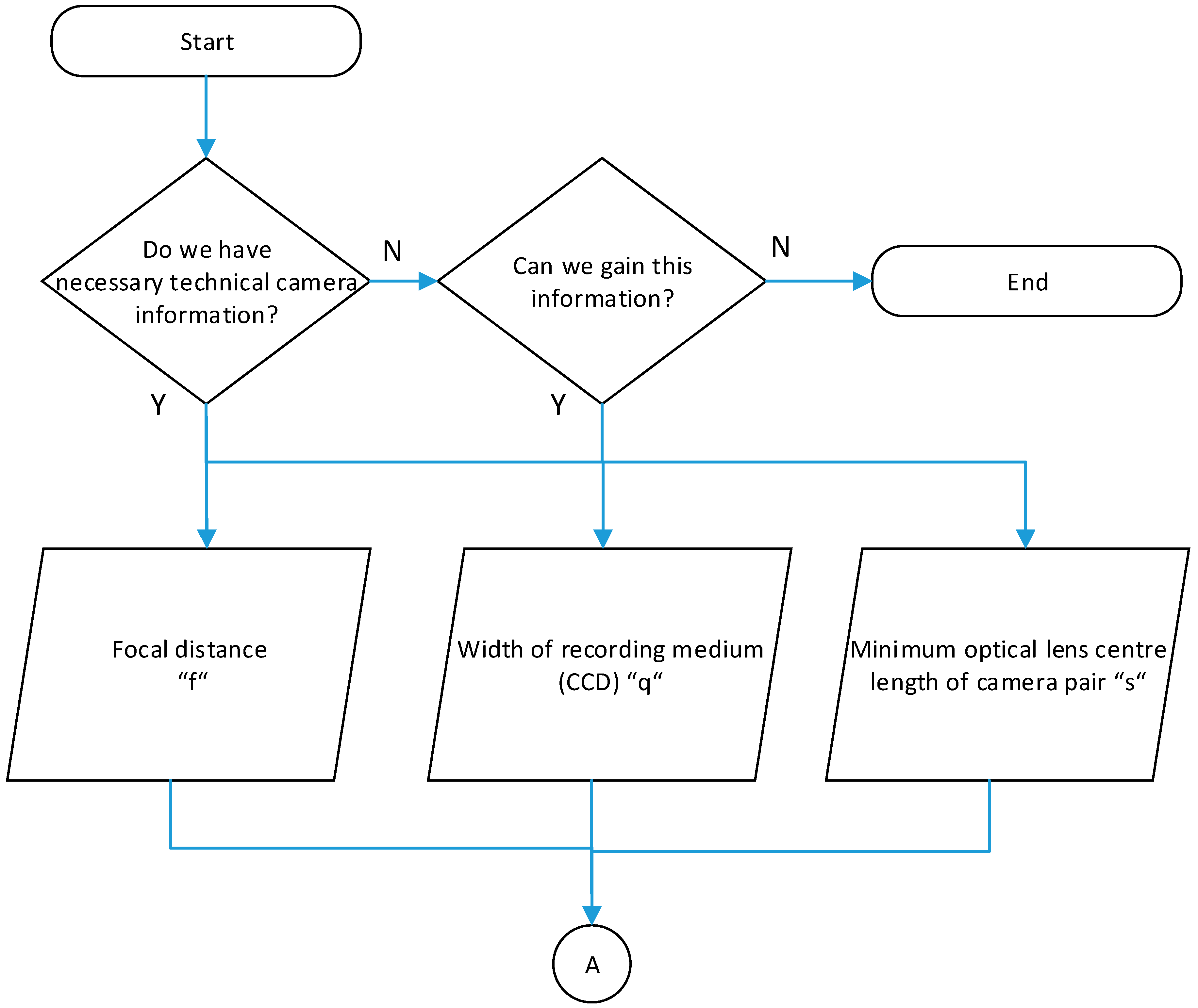
The process of camera data collection is recorded by a form of descriptive diagram (Figure 2). Data about cameras represent the first data group necessary for final parameter calculation and evaluation of stereoscopic recording production. The following two figures are needed for calculation:
  • Focal lens distance “f”;
  • Recording medium width (CCD, …) “q”.
Focal lens distance is a standard technical parameter of each camera. The problem occurs with recording medium width, as this parameter is not normally indicated by a technical camera parameter. The diameter of recording mediums is usually indicated in inches. However, this indication is misleading. An indicated numerical value does not apply to a sensor but the glass cover around it. It is a way of labeling that was used to label electron tubes in TV cameras in the 1950s. It is still used in today’s recording sensors. In case the recording device is equipped with a sensor type charge-coupled device (CCD), it is then possible to find exact dimensions of these sensors. If it is a type of sensor of which dimensions cannot be found, it is possible to find out its dimensions experimentally.
The third-most important data about the camera is the maximum possible optical center of a lens, camera type “s”. When using two identical cameras which are placed next to each other, the size is identical with a camera width.

2.1.2. Process of Display Device Data Collection

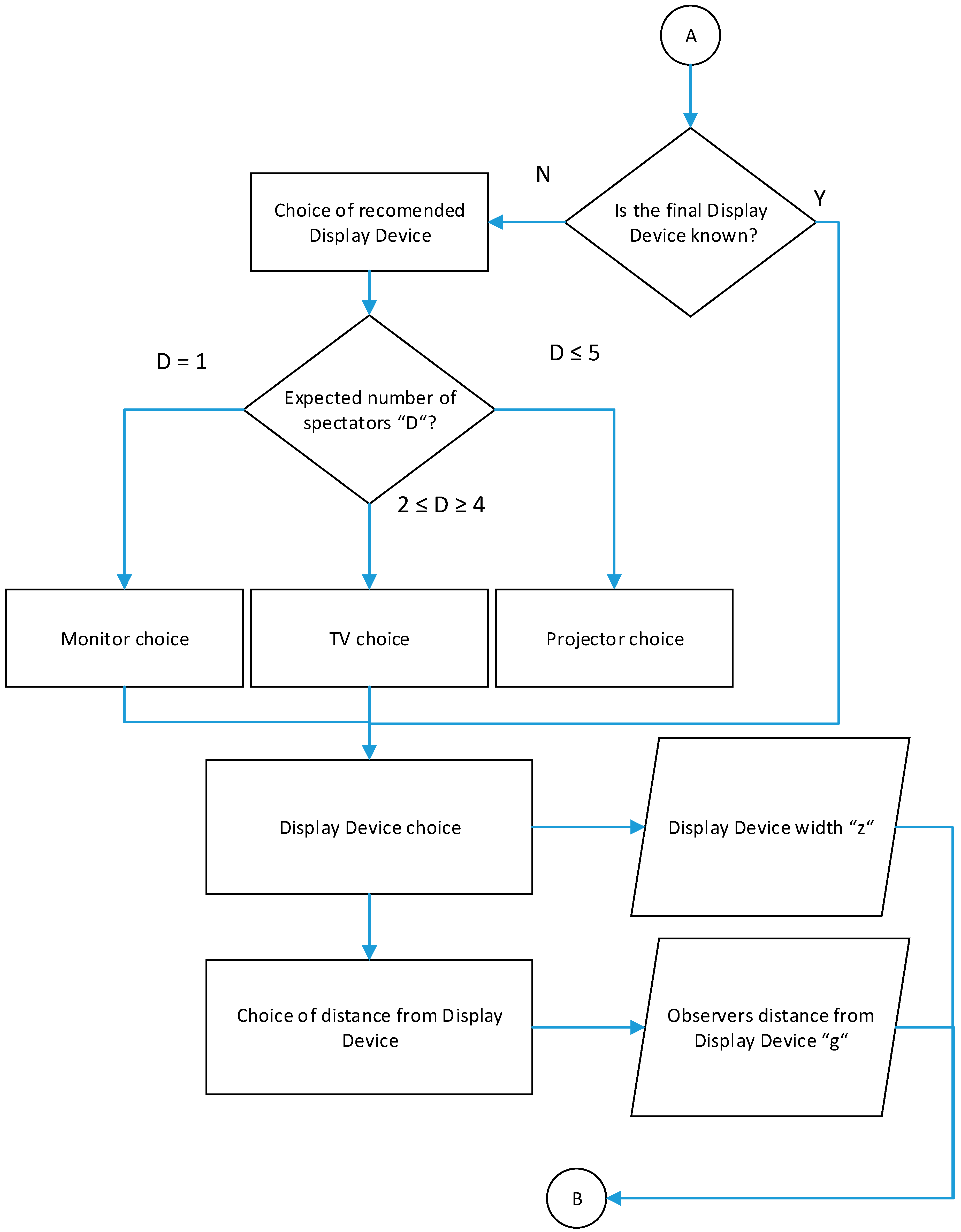
The process of display device data collection is recorded by a form of descriptive diagram (Figure 3). Only the width of the display area is necessary for calculation. In case the final display device is unknown, it is advised to be oriented towards the number of observers of the final display device. From the stereoscopy’s application’s point of view, as an experienced industrial engineer’s tool, three basic uses of stereoscopic recording are recognized:
  • Expert analysis creation of the current state by one specialist. In this case, a stereoscopic recording is being watched by one spectator. Use of a stereoscopic screen, which is connected to a workstation, creator of relevant analyses, could be a good solution.
  • Expert analysis creation of the current state by a small group of specialists. In this case, it is a group of two to four specialists who analyze current state by relevant analyses. The use of a stereoscopic TV is the appropriate solution that makes watching a stereoscopic recording comfortable for a smaller group of people.
  • Induction use and presentation of results. For instance, it is a presentation of a stereoscopic recording to a larger group of people. The use of the stereoscopic projector in an adapted presentation room. The most important requirement is to black-out the room and prevent direct sunlight.
The second figure is related to the distance from an observer to the display device. Furthermore, it is an arrangement of the presentation room. Distance determination from an observer to display device usually depends on specific technical conditions of a presentation room. According to manufacturers’ recommendations and users’ experience, the distance should be two or three times the diagonal of the display device [20,21,22]. However, such recommendations are only indicative and very subjective. The evaluation must always be based on the real distance of the observer from the display device.

2.1.3. Process of Space Data Collection

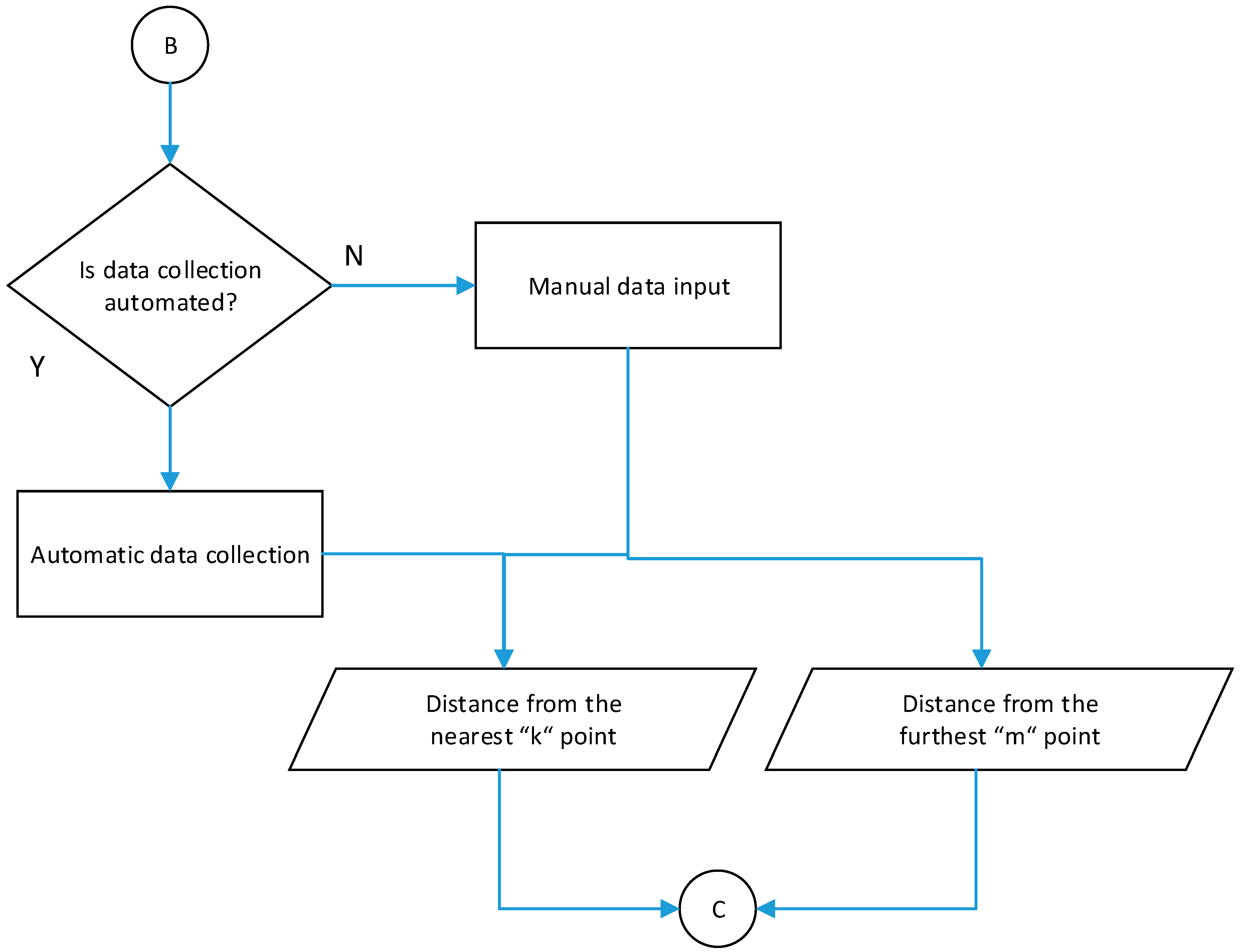
The process of space data collection is recorded by a form of descriptive diagram (Figure 4). There are only two necessary figures for the recorded space. First is the distance of the closest recorded point and the second is the distance of the furthest recorded point. The easiest way is a manual collection of this data and its entry afterward. To speed up the process of space data collection, it is advised to use the laser rangefinder. There is also a question of this collection’s automatization. The use of an automated measuring system, which would analyze recorded space and measure required parameters, could result in the automatization of this process. However, application of such a system would require further research and development.
Having collected all the necessary data from the three processes (Section 2.1.1, Section 2.1.2 and Section 2.1.3), the process of a stereoscopic recording’s creation follows. The creator of a stereoscopic recording must select one of the two following ways of a stereoscopic recording’s creation:
After selecting a way of a stereoscopic recording’s creation, the process of the input camera parameter calculation follows. This is to make a correct stereoscopic recording (Subchapter of the relevant way of a stereoscopic recording’s creation is indicated in brackets).

2.1.4. Process of Input Parameter Calculation for Parallel Camera Axes Option

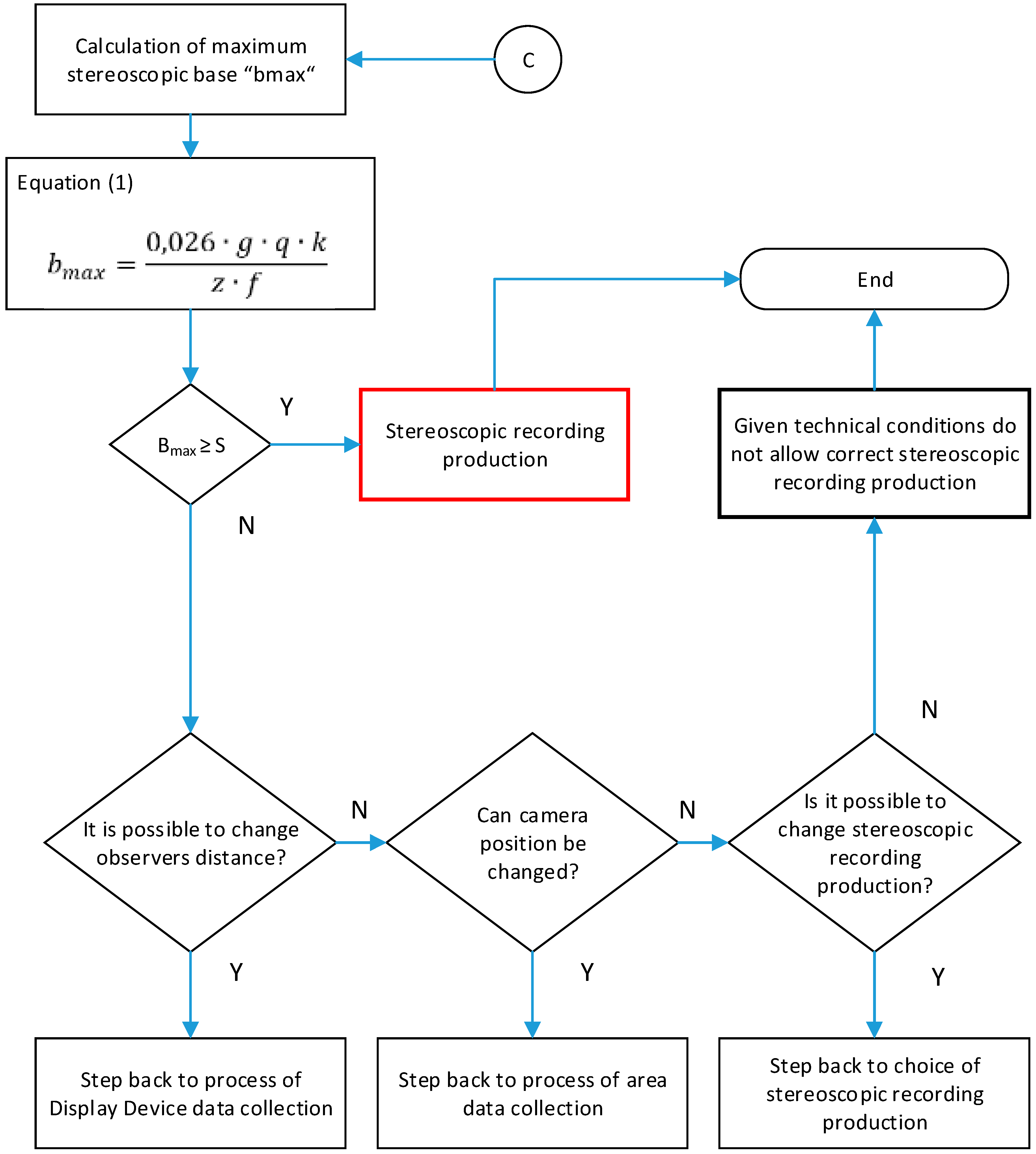
The process of the input parameter calculation for parallel camera axes option is recorded by a form of descriptive diagram (Figure 5). The process of the input camera parameter calculation enables us to calculate the maximum possible camera distance whilst maintaining the stereoscopic recording’s correctness considering the biological requirements for human spatial vision. The formula for bmax Equation (1) is completed by a value of the maximum recommended observation angle of 1.5° value.
b max = 0.026 · g · q · k z · f
where bmax = maximum correctness of the stereoscopic base (distance of camera centers), g = observer’s distance from display device, q = width of recording equipment, k = distance from the nearest recorded point, z = width of display device, and f = focal lens length.
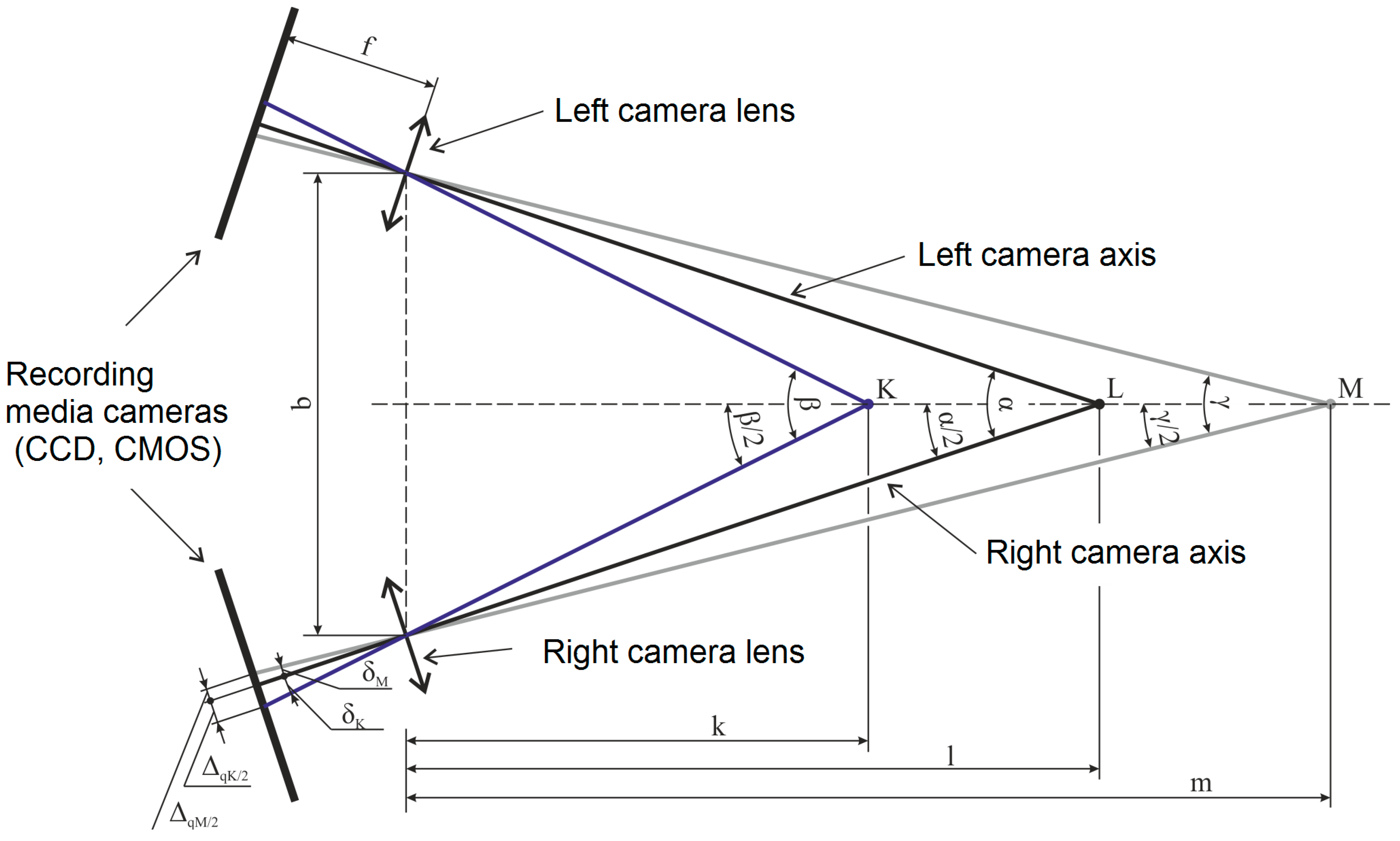
A graphical expression of parameters can be seen in Figure 6.
After the calculation of the maximum correct stereoscopic base “bmax”, comparison with the minimum distance possible of camera centers “s” follows. In other words, verification of a possibility to reach the required distance between camera centers by specific technical equipment follows.
If “bmax ≥ s”, it is then possible to produce a required stereoscopic recording with specific technical equipment. The value “bmax” is the maximum correct value of the stereoscopic base. Therefore, all following lower values will be correct too. The calculation is used to determine the maximum correct stereoscopic base value that cannot be exceeded.
If “bmax < s”, it is then impossible to produce a stereoscopic recording. It is then necessary to consider possible changes of each input parameter in the following order, according to a descriptive diagram:
  • Observer’s distance change;
  • Camera’s position change;
  • Change in a way of a stereoscopic recording production.
Moreover, all the changes have been applied and “bmax” still has not reached the required value, it is not possible to produce a stereoscopic recording in such conditions and with such technical equipment.

2.1.5. Process of Convergence Point Determination

The process of convergence point determination is recorded by a form of descriptive diagram (Figure 7). The convergence point could be selected by a direct task or calculation. Convergence point position is very important when producing a stereoscopic recording. In the case of converging camera axes, it creates a border between a negative and positive parallax. Therefore, it determines the position of the display device, given the reproduced space on this display device. In other words, it determines which objects will be displayed in front of the display device and which is the depth of the display device.
In case it is necessary to record the great depth or shallow depth of space from a short distance, it is advised to use the calculation for the optimal position of convergence point Equation (2). This calculation is an individual author’s work.
l opt = b 2 · tan ( arctan b 2 · m + arctan b 2 · k 2 )
where lopt = optimal distance of convergence point, b = stereoscopic base (a distance of camera centers), k = distance of the closest recorded point, and m = distance of the furthest recorded point.

2.1.6. Process of the Input Parameter Calculation for Converging Camera Axis Variation

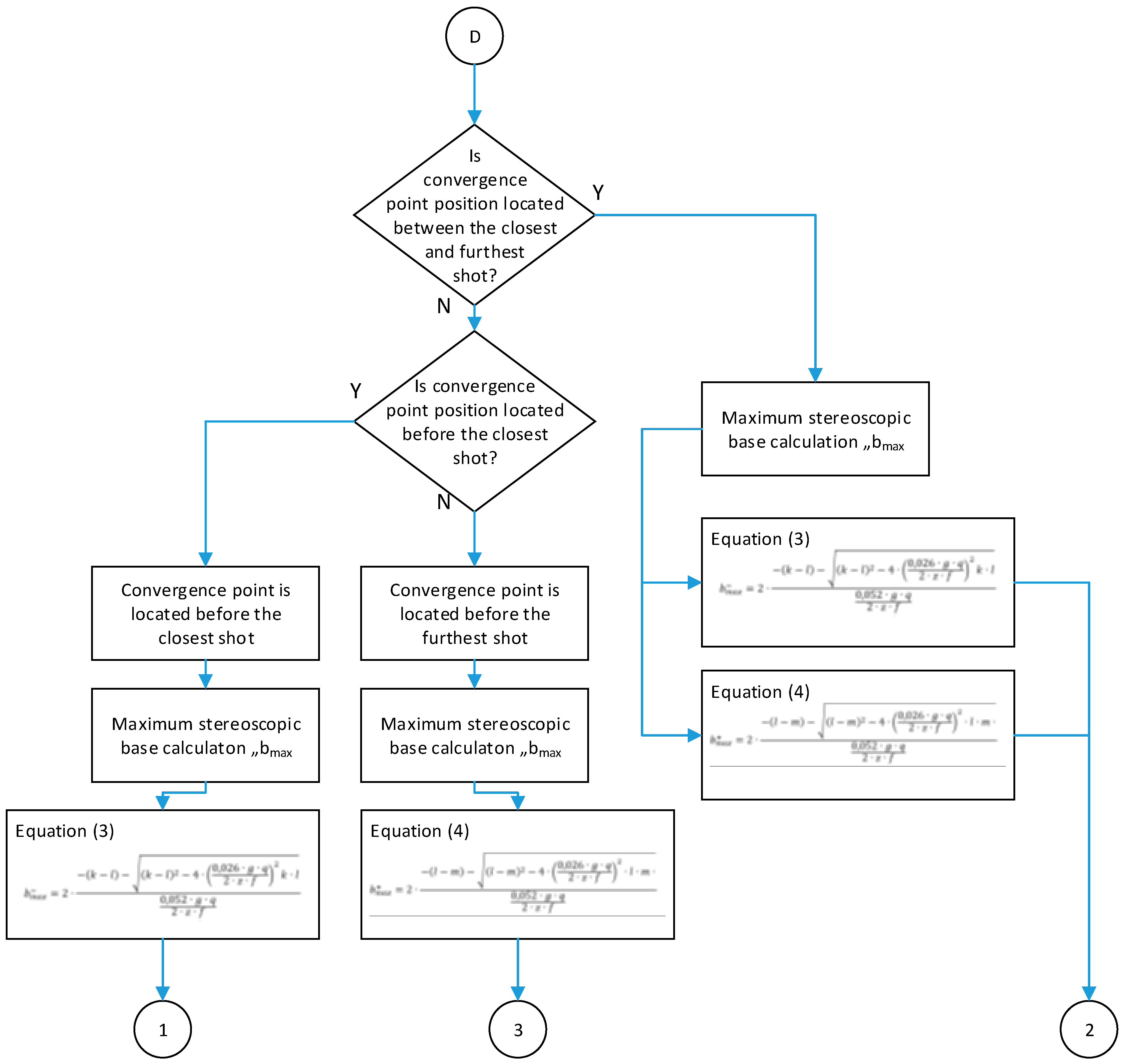
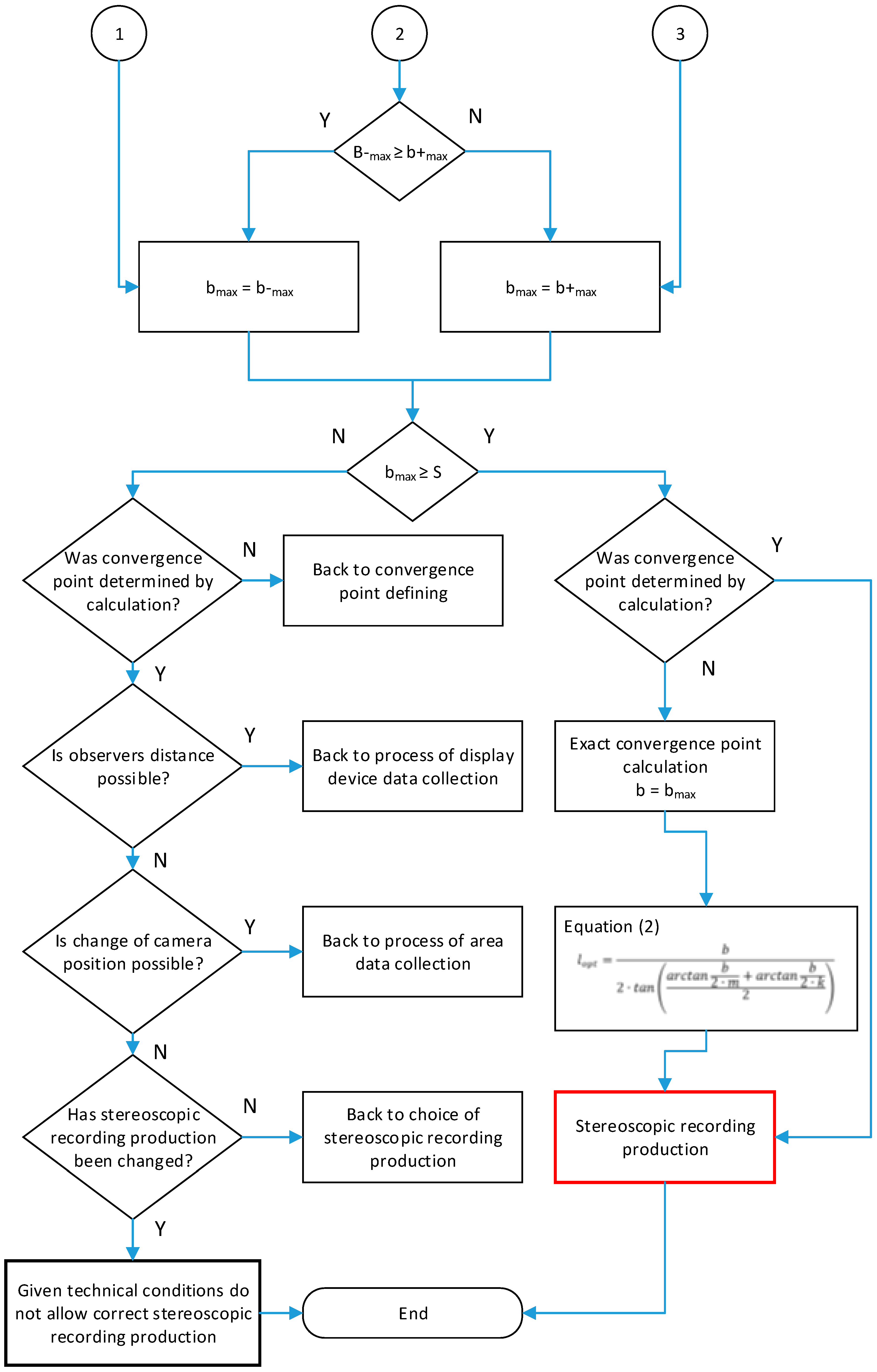
The process of the input parameter calculation for converging camera axis variation is recorded by a form of a descriptive diagram (Figure 8 and Figure 9).
Determinant factor for converging camera axis variation is the calculation of the convergence point position. There are three basic convergence point position variations:
  • The distance of the convergence point is shorter or equal to the distance of the closest recorded point.
  • The distance of the convergence point is longer compared to the distance of the closest recorded point. It is also shorter than the distance of the furthest recorded point.
  • The distance of the convergence point is longer or equal to the distance of the furthest recorded point.
The convergence point position is linked to another calculation. This is due to a difference in points situated before and after the convergence point and their geometry. This results in different formulas for the calculation of mutual image shift and its absolute value. Furthermore, this applies to objects situated before and after the convergence point.
It was necessary to derive a formula in order to calculate the maximum correct stereoscopic base. The maximum correct stereoscopic base calculation is derived on the basis of original geometry. This derivation is an individual author’s work.
Moreover, in order to calculate the maximum correct stereoscopic base, it is necessary to divide the calculation into two formulas. The first formula is linked to the point before convergence (negative parallax area), and the second formula to the point after convergence (positive parallax area). The first derived calculation will describe the point before convergence.
In order to calculate “bmax”, the following three values can only be considered:
  • Δqk/2: Half of the mutual point shift’s absolute value (its value could be determined according to the maximum recommended value of an observation angle);
  • k: The distance of the closest recorded point;
  • l: The distance of the convergence point.
After the maximum angle value determination of δM (given the maximum recommended final observation angle and subsequent modifications) the formula for a maximum correct stereoscopic base in negative parallax area calculation will be as follows:
b max = 2 · ( k l ) ( k l ) 2 4 · ( 0.026 · g · q 2 · z · f ) 2 k · l 0.052 · g · q 2 · z · f
The formula for a maximum correct stereoscopic base in positive parallax area calculation could be derived similarly. The final formula is as follows:
b max + = 2 · ( l m ) ( l m ) 2 4 · ( 0.026 · g · q 2 · z · f ) 2 · l · m 0.052 · g · q 2 · z · f
After the maximum correct stereoscopic base “bmax” calculation, according to Equation (3) and Equation (4), comparison with a minimum possible distance of camera centers “s” follows. In other words, the possibility to reach the required distance of camera centers by given technical equipment will be verified.
If “bmax ≥ s”, we can produce the required stereoscopic recording by the given technical equipment. Value of “bmax”, is only the maximum correct value of the stereoscopic base. Therefore, every other lower value will be correct as well. The calculation is used to determine the maximum correct value of the stereoscopic base that cannot be exceeded.
If “bmax < s”, it is then not possible to produce a stereoscopic recording in such conditions. Furthermore, it is necessary to consider possible changes in each input parameter in the following order of the descriptive diagram:
  • Convergence point change;
  • Observer’s distance change;
  • Camera position change;
  • Change in a way of producing the stereoscopic recording.
If after the requested changes “bmax” does not reach the required value, it is not possible to produce a correct stereoscopic recording in such conditions and with such equipment.
Section 2.1.1 and Section 2.1.6 describe individual steps of goal-directed stereoscopic recording production and its methodology. Given the difficulty of each formula and calculation, the methodology has been backed-up by a calculation file.

2.1.7. Set of Recommendations and Warnings When Producing Stereoscopic Material

Set of recommendations and warnings when producing a stereoscopic recording is made by a collection of the most important author’s experience, he or she has gained during the production and observation of stereoscopic recordings:
  • The main difference between the two ways of stereoscopic recording is the parallel camera axes variation is much easier with a lower risk of mistake when producing the stereoscopic recording. However, the converging axes variation enables area recording from a shorter distance, when the convergence point is in an optimal position. This is the case for the parallel axes too.
  • The most important parameter of the converging camera axes variation is a position of the convergence point. This is because it creates a border between positive and negative parallax and it consequently determines parameters of perceived space when producing the stereoscopic recording. Also, its deviation level from optimal position has a big influence on the value of the final and correctly recorded space.
  • When producing a stereoscopic recording, all objects and people that are placed at the front of recording (closest objects and people) should always be complete in both camera scenes. A trimmed image of the closest objects and people is disturbing whilst watching a stereoscopic image. It partially disturbs the observer’s fully-fledged spatial perception.
  • The easiest solution for tired eyes after a long stereoscopic recording watching is making the distance from the observer and display device longer.
  • The best spatial perception is created when watching an image from a shorter distance than the width of the display device. However, watching the image from such a short distance requires an appropriate recording (lower values of mutual image shift).
  • Given the risk of image distortion with converging camera axes, the value of the stereoscopic base should not exceed 10 cm.

3. Results

3.1. Verifying Solutions in Practice

Within the research, various technologies for the creation and reproduction of stereoscopic images have been used. Created video footage used two identical Samsung R10 video cameras, which were mounted on a stand that was the result of its own development and production (Figure 10). Two technologies have been used to reproduce the stereoscopic record. The first was the Nvidia GeForce 3D Vision [23] technology, which was complemented by a compatible Samsung SyncMaster 2233RZ Monitor. The second was the DepthQ projector [24]. Both display technologies work on the principle of active (darkening) glasses, which always release the image for one eye in alternating succession for the left and right eyes. The frequency of alternation is 120 times per second.
It was necessary to verify this proposed solution of a scientific problem in two different areas. The first area verified the proposed methodology with respect to the validity of derived formulas for the calculation of the camera setting parameter together with the verification of the proposed stereoscopic camera system. The second area was verification of proposed methodology and whether it could be used in practice for an experienced industrial engineer in the field of ergonomic analysis.
Verification of the mathematical model and its results was done by an experimental device developed when the research was carried out as shown Figure 10.
All stated values and graphs have been verified and validated by a developed experimental camera system.

3.1.1. Verification and Validation of Derived Formulas and Accuracy of the 3D Camera System

The validity of derived formulas and accuracy of proposed stereoscopic camera system were verified in experimental laboratories. Six stereoscopic recordings with pre-defined camera settings were produced. As formulas for the calculation of camera setting parameters with parallel axis variation were known and verified, only two video recordings were made. This was made to verify the accuracy of the camera system and its settings. The remaining four stereoscopic recordings were produced with a converging camera axis and its settings. Twenty values were measured by six stereoscopic recordings. In addition, two different stereoscopic display devices verified the accuracy of the calculation and camera setting. Results of this measuring can be seen in Table 1.
First, two positions were used for parallel camera axis variation and the following four for converging variation. Video recording and measurements were created in all three video recording parameter setting groups (space parameters, camera parameters, and display device parameters).
When measuring a mutual point shift, values were measured directly on the relevant display device. This was done by a sliding scale.
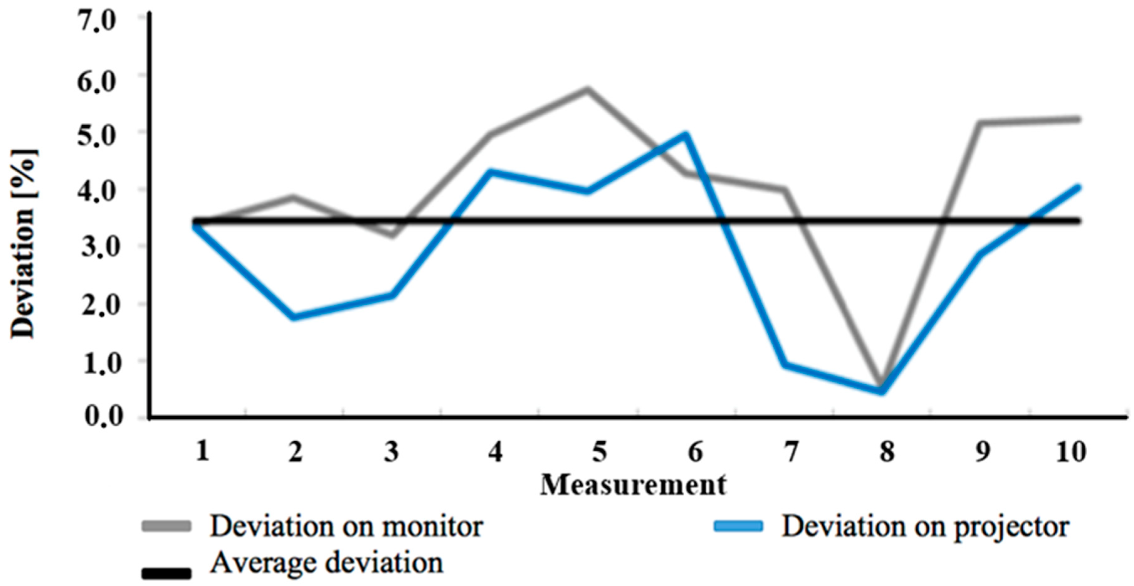
The final percentage deviation of the practically measured and theoretically calculated values are shown in Figure 11.
Deviation values are divided into two groups (depending on the display device) due to a better graph clarity. The total average deviation of measured values is 3.4%, compared to theoretical values. Such deviation value could be considered as sufficient enough for the verification and validation of derived formulas.
The deviation range is an interval from 0.44% to 5.75%. The reason for such a range could be the following:
  • Imprecisions in measuring unit setting of a camera system (laser pointer);
  • Imprecisions in camera system setting;
  • Imprecisions in space parameter measuring;
  • Imprecisions in measuring the final parameters of stereoscopic recording.

3.1.2. Practical Applicability Check When Making Ergonomic Analysis

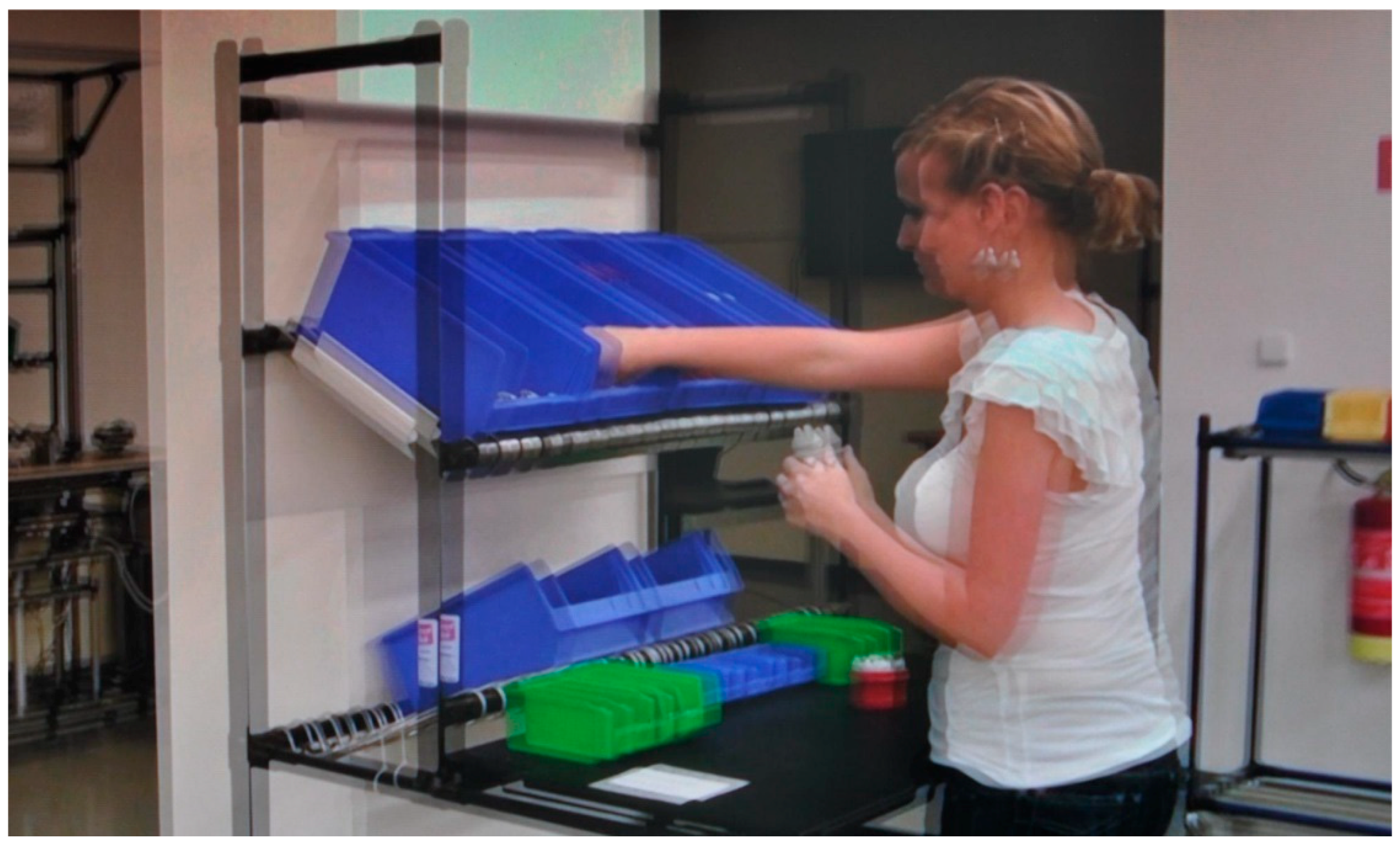
A practical applicability check of stereoscopy, such as a supportive instrument when making ergonomic analysis, is made in cooperation with the Slovak Ergonomic Society, civil association (SES o.z). Video recordings were recorded at Zilina’s Intelligent Manufacturing System (ZIMS) that had been established in order to support new innovative solutions. The model situation of a connecting plug’s manual assembly was created due to the needs of the experimental check. Assembly of the connecting plug was performed after a short training. This assembly was recorded thanks to an advanced stereoscopic camera system. Twelve ergonomic analyses were processed from a created stereoscopic recording afterward [25,26]. Ergonomic analyses were made to confirm or disprove possible contribution of the stereoscopic display when preparing the ergonomic analysis. An example of such a stereoscopic display monitor is shown in Figure 12.
In the same procedure, further stereoscopic records were also created on which ergonomic analyses were processed. In drawing up the analyses, the main partner was SES, o.z. The evaluation was primarily handled by the analysis of Rapid Upper Limb Assessment (RULA), Rapid Entire Body Assessment (REBA), strain index, and Cumulative Traumatic Disorder (CTD) risk index. The methods were selected based on the input parameters they were evaluating. Mainly it was the position and angles of the limbs in the performed activities. For the load of hands in the majority type of work, the correct grip is very important. The position, angle of the hand and the method of the grip are essential to carry out the work so a hand does not get tired or does not get chronic damage. The biggest problem for the hand is its repetitive strength load factor. Excessive strain on the limbs can lead to reduced hand functioning and chronic health problems. The most common health problems are subsequently a carpal tunnel, white finger disease, or trigger finger. Right identification of the location of the hands can be supported using a stereoscopic record. The stereoscopic video was also applied within teaching specifically in ergonomics, analysis, and measurement of work. Students had the opportunity to consult the real production system through the stereoscopic video footage. The stereoscopic video was experimentally used in teaching physical load analysis and RULA. Students were given the task to analyze a specific real workplace and suggest corrective action. Through the stereoscopic record, students could inspect the space of a real production and thus practically apply the explanatory knowledge. In addition to a better overview of the workplace layout, the spatial image also allowed a virtual visit to the real workplace. The response of students was tracked and also their subjective feelings with 3D projection. Response from students was positive and confirmed a better spatial orientation in the workplace when drawing up individual analyses. A qualitative site of teaching was also tracked, which confirmed the improvement of student recognition functions and the overall improvement of their elaborated exercise. However, this result could be also influenced by the better, general prepared of a selected group. For the relevant confirmation of the results, the next detailed research must be done. The teaching applications were not the primary objective of the work presented, nor the verification of the proposed methodology. It only served as a complementary use of the proposed procedures and materials. However, it has indicated the possibility of further routing research and a possible wider application of stereoscopy instruments.
However, the summary shows that the spatial stereoscopic recording and reproduction of the image brings the necessary added value to the process of creating ergonomic analyses based on video footage. The added third dimension for the observer compensates the greatest lack of classical video footage, which is a poor spatial orientation. Practical analysis creation proved the potential of a stereoscopic display as an advanced tool of an industrial engineer [27]. The third dimension of the display device has brought better orientation in the spatial workplace arrangement. When creating an ergonomic analysis, the most essential requirement for an observer is spatial visualization. Spatial reproduction of a video recording creates an impression of presence in the workplace and real worker’s observation. Therefore, it eliminates the need for an observer’s spatial visualization and creates a wider space for an expert, and his or her concentration on the analysis of the workplace. Stereoscopic recordings improve ergonomist’s tasks:
  • Load analysis creation;
  • Time analysis creation;
  • Identification of ergonomic problems in the workplace;
  • Analysis of keeping work procedure.
The need to reduce the time needed for analysis of the current state could be considered as a very frequent requirement in practice. However, it is important to keep details, precision, and quality of a created analysis of the current state when the rapid analysis is required. The need to increase speed and achieve precisions are two opposing requirements when creating analysis. It is actually the 3D display device that creates the necessary support for quick analysis creation in today’s need for quality and precision.
Stereoscopic recording production should be done in the four following steps (Figure 13):
  • Choosing a suitable position for the stereoscopic recording’s production.
    When choosing a suitable camera position, the most important criterion is a recorded space, given the needs of a detailed workplace analysis. It is necessary for the entire workplace of an assessed operation to be recorded. It must be recorded with all its elements. Moreover, it is necessary all the worker’s operations are clearly visible, with clear hand movement.
  • Camera system parameter setting.
    For a quick camera system setting, it is possible to process its calculations into a form of a calculation file that will correctly re-calculate the camera set in a particular space.
  • Recording production.
    When producing a recording it is necessary for at least one complete cycle of an analyzed operation to be recorded. In order to have a better review of the work procedure, it is advised to have more of these cycles recorded.
  • Recording processing and editing.
    Processing consists of editing recorded recordings. The whole process must be recorded, from start till end. In this step, synchronization of a stereoscopic video recording is carried out too.
Production of a stereoscopic video recording is predominantly very time-consuming. It is true that the stereoscopic video production is more time-consuming than the production of a classical video recording. However, the time difference is minimal and the average time needed for each step of stereoscopic recording production depends on the author’s experience (Table 2).
Time-consumption for 3D recording production compared to 2D recording is 20% higher, however, the difference is only seven minutes. There are two steps included within the additional seven minutes. The first step includes the camera system parameter setting. Thus, this step is more time-consuming and is not performed during 2D recordings. Moreover, it usually takes two minutes, together with a calculation file. These two minutes represent the only time extension spent in the workplace. The total time spent in the workplace is a very important factor due to the attempt of limiting distribution of other activities operators perform. The second step involves video recording processing and editing which is also time-consuming. In this step, the video is processed and edited in a way so the analyzed operation could be recorded as a whole. This step is also about synchronization of both scenes. The first recording is completely analyzed and time slots that are chosen record the operation as a whole. The second recording is edited according to chosen times.
A slight increase in time consumption is compensated when making an ergonomic analysis of the workplace. Time compensation is made by providing ergonomic analysis with higher quality in case of spatial vision of the analyzed workplace. A direct spatial workplace vision enables the increase in productivity when analyzing individual ergonomic workplace parameters by the following activities:
  • Analysis of potentially risky activities and operations. When analyzing a workplace, the ergonomist does not create an analysis of all workers’ activities and operations. Such an approach would be very difficult and ineffective. Ergonomist, thanks to his knowledge and experience, needs to quickly identify potential risky activities and operations which he will later analyze in detail. The spatial vision of a particular situation eliminates the need for spatial imagination of the ergonomist and enables him to quickly and effectively identify potential risky activities and operations.
  • Detailed analysis of selected activities and operations. After selecting these potentially risky activities and operations, they are analyzed in detail afterward. Detailed analysis of particular activities requires information about the spatial orientation of a worker during the analyzed situation. Moreover, spatial reproduction of the particular activity’s recording is an appropriate supportive tool that provides necessary information as well as quick and quality making of required analyses.

4. Discussion

The main findings of this study were:
  • The stereoscopic visualization application provides better vision about the spatial layout of the workplace and about spatial orientation of the operator in the workplace when they do their work activities. This was most relevant in the application of stereoscopy in the field of ergonomic analysis of operator work activities. A number of ergonomic analyses were assessed based on the current spatial position of operator orientation, e.g., Ovako Working posture Analysis System (OWAS), RULA, REBA, National Institute for Occupational Safety and Health (NIOSH), low back analysis, static strength prediction, strain index, and Ergonomic Assessment Work-Sheet (EAWS). For all of these analyses, it was a crucial correct evaluation of the actual spatial orientation of the operator, which can be determined very heavily and with insufficient accuracy by using classic 2D records. The study showed that stereoscopic recording and visualization could make easier the determination of the operator’s location in the workspace.
  • For creating stereoscopic records in industrial practice, commercially available camera systems are only applicable under restricted conditions. Commercially available stereoscopic camera systems are primarily designed for use in the entertainment industry or in domestic conditions when creating private movies. Camera systems designed for use in the entertainment industry are characterized by very high quality of use but are also very sturdy and expensive. However, in the case of 3D camera systems for home use, they are affordable but they can be used under a number of limitations. This limitation can be the minimum distance of the nearest point of vision or the minimum possibility of setting the shooting parameters, e.g., the distance and angle of the camera convergence. All these restrictions on available systems are based on their primary conditions of use. In case of creating a recording by the entertainment industry or in the home, we can adapt some elements of recorded space to the camera system parameter, but this adaptation is not possible when recording in the industrial environment. This is because the possibility of organizing the workspace to improve the stereoscopic record could result in distortion of the operator’s activities performed. This could lead to a deterioration of results when ergonomic analyses are carried out, which would not necessarily reflect the real situation in the workplace.
  • When we create our own camera system with a sufficient number of degrees of freedom setting of the scanning parameters, we need to design the algorithm to correct these parameters. The proposed algorithm, along with the derived basic geometry of the stereoscopic camera system with converging camera axes, formed the core of the presented study. The application of the presented procedure will allow for creating high quality and precise stereoscopic records, which, will also respect the biological limits of human vision. The procedure guides the user through the process of acquiring basic input data, which are then used to calculate the resulting parameters of the camera system setting to achieving a quality stereoscopic recording. The geometric model and derived formulas contain a certain degree of simplification, which was assessed as acceptable on the basis of the monitoring of created records. The accuracy of the calculation could be increased, for example, by application of the lens display equation [16] to the original calculation. This could be focused on future work in developing the presented study.

5. Conclusions

The main aim of this scientific issue was to propose a methodology to create and present a stereoscopic recording that could be applied in industrial engineering as a tool for long time stabilization of work positions.
Classical video recording is a common and used tool for industrial engineering. The biggest disadvantage of classical video recordings is poor spatial orientation that could result in an incorrect evaluation of work process key elements.
3D display devices are the ones that provide better awareness about the spatial workplace arrangement and spatial human orientation. Stereoscopy is a new tool for an experienced industrial engineer. It makes an engineer’s work better when it comes to ergonomic studies and in the following research activities of a workplace’s current state:
  • Possible workplace collisions;
  • Identification of workplace ergonomic problems;
  • The physical presence of an ergonomist is not necessary when making an analysis;
  • The possibility of repeated operator’s tasks’ observation and detailed observation of particular tasks;
  • Possibility to review workplace order;
  • Possibility to review whether correct procedures of individual operations are kept;
  • Possibility to analyze how human potential could be used more effectively.
To sum it up, spatial recording and image reproduction bring the necessary added value to the production of ergonomic analysis created due to a video recording. These outputs make solving work positions suitable for work, which means less worker rotation and even added value makes working position sustainable for a long time.

6. Patents

The crux of the methodology presented is protected by the utility model, utility model number 7683 registered by the Industrial Property Office of the Slovak Republic [28].

Author Contributions

All authors contributed to writing the paper. Documented the literature review, analyzed the data and wrote the paper. All authors were involved in the finalization of the submitted manuscript. All authors read and approved the final manuscript.

Acknowledgments

This research was supported by the Slovak Grant Agency: KEGA–022ŽU-4/2018.

Conflicts of Interest

The authors declare no conflict of interest.

References

  1. Holmes, O.W. The Stereoscope and the Stereograph. 1859. Available online: http://www.stereoscopy.com/library/holmes-stereoscope-stereograph.html (accessed on 20 February 2019).
  2. Wheatstone, C.H. Contributions to the Physiology of Vision—Part the First. 1838. Available online: http://www.stereoscopy.com/library/wheatstone-paper1838.html (accessed on 20 February 2019).
  3. Wheatstone, C.H. Contributions to the Physiology of Vision—Part the Second. 1852. Available online: http://www.stereoscopy.com/library/wheatstone-paper1852.html (accessed on 20 February 2019).
  4. McKay, H.C. Three Dimensional Photography. 1953. Available online: http://3d.curtin.edu.au/library/mckay.cfm (accessed on 20 February 2019).
  5. Lipton, L. Foundations of the Stereoscopic Cinema. 1982. Available online: http://3d.curtin.edu.au/library/foundation.cfm (accessed on 20 February 2019).
  6. Howard, I.P.; Rogers, J. Binocular and Stereopsis; Oxford Psychology Series; Oxford University Press: Oxford, UK, 1995; ISBN 978-0195084764. [Google Scholar] [CrossRef]
  7. Bimper, O.; Raskar, R. Spatial Augmented Reality; A K Peters/CRC Press: Wellesley, MA, USA, 2005; ISBN 978-1-56881-230-4. [Google Scholar]
  8. Lee, C.H.; Diverdi, S.; Höllerer, T. An Immaterial Depth-Fused 3D Display; ACM: New York, NY, USA, 2007; ISBN 978-1-59593-863-3. [Google Scholar] [CrossRef]
  9. Martín, S.; Suárez, J.; Orea, R.; Rubio, R.; Gallego, R. GLSV: Graphics library stereo vision for OpenGL. Virtual Real. 2009, 8, 51–57. [Google Scholar] [CrossRef]
  10. Livesey, R.J. Some stereoscopic studies of the moon. J. Br. Astron. Assoc. 1971, 82, 38–41. [Google Scholar]
  11. Merchant, A.C. Three-Dimensional Stereoscopic Anatomy. Arthrosc. J. Arthrosc. Relat. Surg. 2011, 27, 1603. [Google Scholar] [CrossRef] [PubMed]
  12. Halfen, A.F. A New Stereoscopic (3D) Media Database and Teaching Strategy for Use in Large-Lecture Introductory Geoscience Courses. J. Geosci. Educ. 2014, 62, 515–531. [Google Scholar] [CrossRef]
  13. Bruno, F.; Caruso, F.; Napoli, L.; Muzzupappa, M. Visualization of industrial engineering data visualization of industrial engineering data in augmented reality. J. Vis. 2006, 9, 319–329. [Google Scholar] [CrossRef]
  14. Bougaa, M.; Bornhofen, S.; Kadima, H.; Rivière, A. Virtual Reality for Manufacturing Engineering, The Factories of the Future 2015, Applied Mechanics and Materials. pp. 789–790. Available online: www.scientific.net/AMM.789-790.1275 (accessed on 20 February 2019).
  15. Wolfartsberger, J.; Zenisek, J.; Sievi, C. Chances and Limitations of a Virtual Reality-supported Tool for Decision Making in Industrial Engineering. IFAC-PapersOnLine 2018, 51, 637–642. [Google Scholar] [CrossRef]
  16. Červeň, I. Fyzika po kapitolách—Optika; Slovenská technická univerzita: Bratislava, Slovakia, 2007; p. 75. ISBN 978-80-227-2674-0. [Google Scholar]
  17. Gašo, M.; Tureková, H. Význam Panúmovej oblasti pri tvorbe stereoskopických záznamov. In Pokrokové Priemyselné Inžinierstvo, Proceeding of the Invent 2010, Terchova, Slovakia, June 2010; GEORG: Terchova, Slovakia, 2010; pp. 132–135. ISBN 978-80-89401-12-3. [Google Scholar]
  18. Gašo, M. Ergonómia stereoskopických záznamov. In Proceedings of the Stereoskopických Záznamov. Ergonómia 2010—Progresívne Metódy v Ergonómii, Zborník Prednášok, Žilina, Slovakia, 24–25 November 2010; pp. 106–110, ISBN 978-80-970588-6-9. [Google Scholar]
  19. Gašo, M.; Smutná, M. The relation of input quantities for creation of stereoscopic record. In Proceedings of the Transcom 2011—9th European Conference of Young Research and Scientific Workers, Žilina, Slovakia, 27–29 June 2011; pp. 59–62, ISBN 978-80-554-0370-0. [Google Scholar]
  20. Available online: https://www.pcrevue.sk/a/Ako-vyberat-televizor (accessed on 28 March 2019).
  21. Available online: https://prevodyonline.eu/sk/vzdialenost-tv.html (accessed on 28 March 2019).
  22. Available online: https://www.samsung.com/sk/tvs/sprievodca/uhlopriecka/ (accessed on 28 March 2019).
  23. Available online: https://www.nvidia.com/object/3d-vision-main.html (accessed on 28 March 2019).
  24. Available online: http://www.depthq.com/ (accessed on 28 March 2019).
  25. Slamková, E.; Dulina, L.; Tabaková, M. Ergonómia v Priemysle; GEORG: Žilina, Slovakia, 2010; p. 262. ISBN 978-80-89401-09-3. [Google Scholar]
  26. Smutná, M.; Dulina, L. Metódy a Softvérová Podpora v Priemyselnej Ergonómii; Slovenská Ergonomická Spoločnosť (SES): Žilina, Slovakia, 2010; p. 146. ISBN 978-80-970525-6-0. [Google Scholar]
  27. Gregor, M.; Medvecký, Š.; Mičieta, B.; Matuszek, J.; Hrčeková, A. Digitálny Podnik; KRUPA Print Žilina: Žilina, Slovakia, 2006; p. 148. ISBN 80-969391-5-7. [Google Scholar]
  28. Gašo, M.; Mičieta, B. Spôsob Určenia Bodu Konvergencie a Veľkosti Stereoskopickej Základne s Konvergujúcimi Osami Kamier; Úžitkový vzor č. 7683; Úrad Priemyselného Vlastníctva: Banská Bystrica, Slovakia, 2016; p. 11. [Google Scholar]
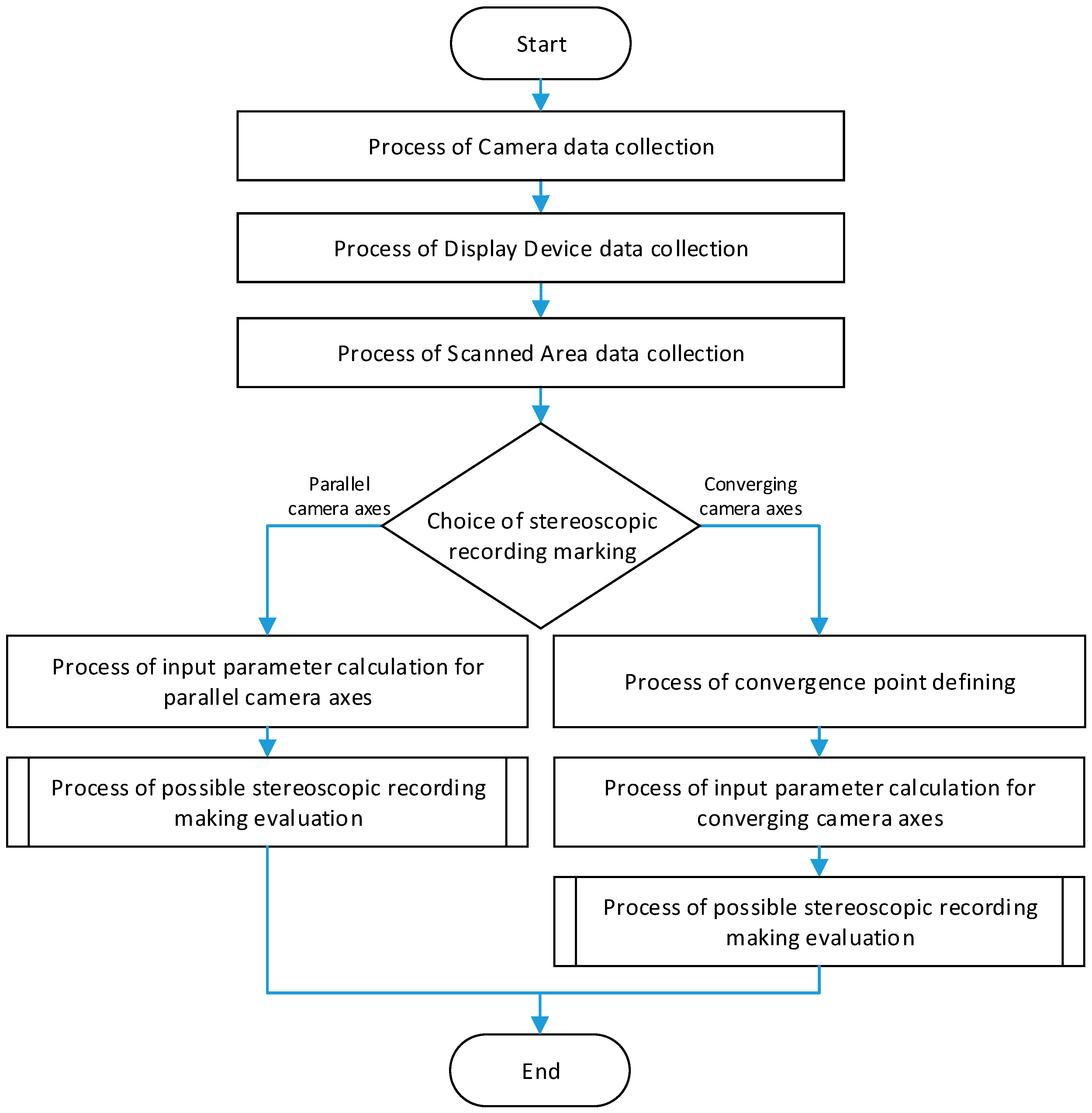
Figure 1. Framework procedure of goal-directed stereoscopic recordings and their production.
Sustainability 11 02194 g001
Figure 2. The process of camera data collection.
Sustainability 11 02194 g002
Figure 3. The process of display device data collection.
Sustainability 11 02194 g003
Figure 4. The process of space data collection.
Sustainability 11 02194 g004
Figure 5. Input parameter process of the calculation and evaluation for the parallel axis variation.
Sustainability 11 02194 g005
Figure 6. The approximation plane geometry with constant approximation movement.
Sustainability 11 02194 g006
Figure 7. The process of convergence point determination.
Sustainability 11 02194 g007
Figure 8. The process of the input parameter calculation for converging camera axis variation (section A).
Sustainability 11 02194 g008
Figure 9. The process of the input parameter calculation for converging camera axis variation (section B).
Sustainability 11 02194 g009
Figure 10. Developed a camera system.
Sustainability 11 02194 g010
Figure 11. Percent deviation graph of measured and calculated values.
Sustainability 11 02194 g011
Figure 12. Example of stereoscopic video recording.
Sustainability 11 02194 g012
Figure 13. Stereoscopic video recording production steps.
Sustainability 11 02194 g013
Table 1. Comparison of measured and calculated parameters of a stereoscopic recording.
Number of PositionInput ParametersCalculated ParametersMeasured ParametersDeviation [mm]Deviation [%]
b [mm]xK [mm]xL [mm]xM [mm]z [mm]ΔzK [mm]ΔzM [mm]ΔzK [mm]ΔzM [mm]ΔzK [mm]ΔzM [mm]ΔzK [%]ΔzM [%]
1402500xx4739.19x9.5x0.31x3.37x
181035.17x34x1.17x3.33x
263.52000xx47316.85x17.5x0.65x3.86x
181069.78x71x1.22x1.75x
344900100012504732.815.052.94.80.090.253.24.95
181010.7319.3310.518.50.230.832.144.29
444853100013344734.356.334.66.60.250.275.754.27
181016.6624.216230.661.23.964.96
563.5810100013504738.549.458.29.50.340.053.980.53
181032.736.1633360.30.160.920.44
663.55801000113047326.364.222541.360.225.165.21
1810100.8916.159815.52.890.652.864.02
Table 2. Labor-intensity comparison of classical and stereoscopic video recording production.
Stereoscopic Recording Process StepsTime Consumption of Steps
2D Recording Production3D Recording Production
Selection of suitable camera position3 min3 min
Camera system parameter setting0 min2 min
Recording making15 min15 min
Recording processing and editing15 min20 min
33 min40 min
100%120%