Innovative Upscaling of Architectural Elements for Strengthening Building Structures


Centre for Sustainable Infrastructure, Swinburne University of Technology, Melbourne, VIC 3122, Australia
Sustainability 2019, 11(9), 2636; https://doi.org/10.3390/su11092636
Submission received: 5 April 2019
/
Revised: 1 May 2019
/
Accepted: 1 May 2019
/
Published: 8 May 2019
(This article belongs to the Special Issue Structural Upgrading Systems for Sustainable and Resilient Concrete Infrastructure)
Abstract
:For conservation of heritages or life prolongation of aged buildings that contributes to environmental sustainability, there is a global need of structural strengthening or upgrading so as to restore their original functions or fulfil more stringent performance requirements stipulated in modern design codes of practice. However, the actual implementation is usually met with resistance from the property owner; hence, it is desirable to adopt an effective, economical and less invasive technique. In order to provide a further incentive, this article explores an innovative idea of upscaling decorative architectural elements, such as brackets, knee braces and corbels, in order that they also possess adequate strength capacity to resist extreme loadings such as earthquake actions. The required dimensions of architectural brackets for seismic retrofitting of concrete beam-column joints are calculated for different levels of seismicity through a parametric study. It is demonstrated that the proposed design can enhance both the aesthetics and structural performance of a building. This exemplifies how art can be integrated into engineering design for solving real-world problems.
1. Introduction
Buildings are the basic needs for the sustainability of human beings and society. Many of them can remain standing for hundreds or even thousands of years. However, the buildings may suffer from different degrees of deterioration depending on the environmental conditions and the construction materials used. In addition, they might be damaged or destroyed in extreme events, like typhoon, earthquake and fire, which were not considered when they were designed and constructed.
Architectural conservation and restoration have gained significant momentum over the last two centuries. It began with the preservation of ancient structures [1] and has then been extended to the restoration of heritage buildings for cultural, religious, social and architectural reasons [2]. There is also a growing interest to prolong the life of older buildings for adaptive re-use from the perspectives of resource management and environmental sustainability [3,4]. In some cases, heritage buildings are restored and utilised for a different or an additional purpose [5], of which the structural performance requirements could be more stringent. Hence, structural retrofitting or upgrading are needed.
On the other hand, through advancements of science, engineering and technology, there have been significant improvements in the understanding of the nature of various environmental loadings and the corresponding structural response behaviours. The methods and philosophy of structural design have always been evolving, especially in the past few decades. The performance and safety requirements stipulated in modern design codes of practice are also changing regularly. Hence, there is always a need to investigate if existing buildings can fulfil the updated design requirements or not.
When certain buildings are deemed inadequate, remedial measures should be taken to upgrade or strengthen certain parts of the structures. However, if the cost involved is considered too high and the remedial strategy is not required by law, then the building owners might simply ignore the potential risk and take no action. Even if structural upgrading is mandated by law, demolishing the old building and reconstructing a new one might be considered more cost-effective. However, this is not desirable from sustainability perspectives.
A typical example is about seismic retrofitting of building structures, especially in regions of low-to-moderate seismicity. This is always a challenging endeavour as the seismic risk is typically underrated by the public. Implementation of seismic retrofit has commonly been hindered by the opposition from building owners partly due to the perceived high costs and the inevitable interruption to economic activities that may lead to a reduction of profits, productivity and/or service provisions. Moreover, the modifications or additions resulted from the retrofitting may have a negative impact on the building’s appearance, and possibly reduce its usable space, and in turn, affect property value and rental. Hence, it is desirable to adopt structural strengthening and retrofitting techniques which are cost-effective, practical, less invasive, and also aesthetically more pleasing. This article addresses exactly this by proposing an innovative design that fulfils all these requirements.
There are a wide variety of effective techniques that exist in the industry, as well as new inventions and ideas that can be found in the literature [6,7]. Infill wall and cross brace can be used to stiffen a structural frame, whilst buckling-restrained braces [8] and various types of dampers [9,10] can dissipate a significant amount of energy. These techniques are effective in reducing displacement demand, but the added structural elements would result in a significant change in the appearance of the building. These techniques are commonly used in regions of high seismicity, but they are usually not welcome in regions of low-to-moderate seismicity.
On the other hand, the capacity of reinforced concrete columns can be enhanced by jacketing with the use of steel or fibre-reinforced polymer (FRP) composites. The confinement effects can lead to increased ductility and shear strength of the column, as well as the strength of concrete. These approaches are effective in creating a strong-column weak-beam system, which can result in a more desirable failure mechanism in an extreme event. Meanwhile, it is practically and economically viable to implement.
Whilst there are effective techniques for enhancing the capacity of columns, the vulnerability of beam-column connections is sometimes ignored partly because they are typically not considered in routine structural analysis. Also, the failure mechanism of concrete beam-column connections is more complex and less understood compared to that of beams and columns. The problem is compounded by the fact that the amount of steel reinforcement in the joint is usually inadequate in regions of low-to-moderate seismicity.
Whilst this remains as a major knowledge gap, it has been observed in past earthquake and other extreme events that shear failure at beam-column connections is a common cause of the structural collapse (refer to Section 2.3 for examples). Likewise, other types of connections between structural elements are also prone to damage or failure in extreme events. A similar situation exists in the connections between slab and column or wall. The connection between the precast slab and supporting beam with inadequate seating width is at stake when the building is swayed significantly. The corner between two pieces of walls could be exposed to stress concentration when there are excessive torsional responses induced by lateral loads.
Steel or FRP composites jacketing has also been proposed for retrofitting connections, it is however not always possible to wrap the whole connection due to accessibility issues. Another possible approach is to install an element, such as a diagonal haunch [11,12], a steel angle [13], an L-profile [14] or a buckling-restrained knee brace/haunch [15,16] at the corner of two connecting members (e.g., beam and column). The element can be attached to the members using post-tensioning bar system external to the structure, whilst the use of post-installed anchoring system could make these techniques less invasive and practically more feasible [17,18]. In addition, joint enlargement is potentially a feasible strategy in certain cases [19,20].
Beyond the technical aspects, it would be desirable to provide more incentives to encourage building owners to adopt structural upgrading or retrofitting strategies. Whilst the search for beauty is often a neglected dimension in a building renovation project or a sustainability policy [21], aesthetic value has a strong influence on consumer behaviour [22] and should be taken into account in any housing quality improvement projects [23].
It is noteworthy that there is a gradual movement, initiated by the Rhode Island School of Design (http://stemtosteam.org/), to integrate “art” into the STEM (science, technology, engineering, and mathematics) fields of education and research. This has been named as STEAM (science, technology, engineering, art, and mathematics) that aims to encourage innovation, and to use engineering or technology in imaginative designs or creative approaches to real-world problems whilst building on mathematics and science base. In 2013, a joint resolution (H. RES. 51) was introduced in the United States House of Representatives in the 113th Congress expressing the sense that adding art and design into the STEM fields encourages innovation and economic growth.
This article explores the technical feasibility of an innovative upscaling of architectural elements, such as knee braces, brackets and corbels (see typical examples in Figure 1), for serving the functional purpose of strengthening building structures by resisting high magnitude of loads, and at the same time, enhancing the aesthetic value of the building. Suitable architectural elements can be chosen to match the appearance of the existing building. This concept could be particularly attractive for restoring heritage buildings. However, these elements are typically used for supporting minor loadings and for decorative purpose only. The research question is whether the design objectives of structural strengthening or upgrading (e.g., in terms of the required strength capacity) can be achieved by using architectural elements of reasonable length and cross-section.
This article addresses this with a focus on a steel bracket which is a simple and commonly used form of architectural elements. The basic design is shown in Figure 2b which was photographed by the author at the platform of Glenferrie Train Station in Melbourne, Australia, where the main campus of the Swinburne University of Technology is located. Derivatives of this design with more decorative features are shown in Figure 2c,d. The curved knee brace takes up less headroom as compared to a diagonal knee brace, which is more desirable from the occupants’ perspective.
In this article, the typical needs for structural upgrading or retrofitting are discussed in Section 2 through a series of case studies encountered by the author, whilst the possible ways of applying the proposed design are also described. The fundamental mechanics are explained and the basic formulae for static elastic analysis and design of the architectural brackets under various boundary conditions are given in Section 3. A parametric study on the application of the architectural brackets is then presented in Section 4, which demonstrates the technical feasibility of the proposed concept as a practical and aesthetically pleasant technique for regions of different levels of seismicity.
2. Global Needs of Structural Upgrading
2.1. Conservation of Damaged Heritage Buildings
Historic structures are common all around the world. There are often public awareness and wishes of retaining and conserving those structures. However, they were typically not designed to modern structural design requirements and the construction materials used might not satisfy current standards. In addition, they are probably damaged or deteriorated due to environmental effects, natural hazards, man-made activities or a combination of various causes.
An example is a group of heritage masonry buildings of the former Chain of Ponds Inn, which is located on Old New England Highway, Liddell, in the State of New South Wales (NSW), Australia. They were made of ashlar stone and sandstock brickwork (Figure 3a) in the early 1840s and the site is registered on the NSW State Heritage Register. There were originally four buildings, but one of those collapsed in a windstorm in 2011. All the buildings have not been inhabited since the 1960s.
As the heritage site is close to a coal mine of the Liddell Coal Operations with open cut blasting, the author and his colleagues were commissioned to undertake a vulnerability assessment and to set a safe ground vibration limit for these buildings when they were subjected to ground vibrations from near-field blasting [24]. Based on the visual inspection of the exterior conditions and visible features of the buildings during the site visit on the 28th of November 2014, the buildings exhibited a significant level of deterioration and damage. Apparent pre-existing damages were observed in the stoneworks in both buildings. Repair works were performed using impermeable Portland cement-based mortar and render. Vertical cracks have been formed below the upper window. Large vertical cracks have also been formed from the ground to the roof of the building. Endplates of horizontal steel tie supports through the wall could be seen. It was also reported that termite damage, amongst other causes, has affected the stability of the building [25].
The timber verandah columns had damage which occurred over time as evidenced by the loss of sections and the rotting of members (Figure 3b). Excessive damage could also be observed along the beams supporting the first floor of the timber verandah and the timber verandah columns. Stability issues could be a matter of concern. The buildings’ owner has carried out major conservation work on the timber verandah and to some other structural timberworks in 2015. However, it was identified that possible stability issues with the heavily deteriorated timber verandah (Figure 3b) or unsupported (discontinuous) chimneys (Figure 3a) could still be of concern.
Extra supports for the damaged timber verandah are needed to prevent potential further damages due to ground vibrations induced by nearby mining activities or other causes. The unsupported chimneys also require bracings to prevent further damage. It may be prudent if a holistic and higher level of upgrading strategy is carried out to enhance the structural stability of the historic buildings. The strengthening scheme proposed in this article could be an attractive option, whilst construction material compatible with the existing structures (e.g., timber) can be adopted.
2.2. Strengthening of Deteriorating Heritage Buildings
On the 14th of October 1968, an Ms 6.8 (Mw 6.58) earthquake occurred at Meckering, in the State of Western Australia (WA). On the 50th anniversary, the Australian Earthquake Engineering Society has organized a site visit to the town of Meckering and the Shire of York. Thus, the author had the opportunity to visit a number of heritage buildings and their restoration works. The historic York Town Hall was built in 1911 (Figure 4a) and is registered on the WA State Register of Heritage Places. It is a brick and iron roofed building. It is a spectacular piece of architecture and is a nationally recognised landmark, not only for its aesthetic characteristics but also its civic functions and social purposes. Extra bracing for the parapet walls may be required to maintain integrity.
The site of the former York Flour Mill and the associated buildings is also registered on the WA Heritage Register. The York Flour Mill (Figure 4b) was constructed in 1892 to mill flour for York and the surrounding districts, and for export. It represents the culmination of the production of flour in York and was an important part of the economic well-being of the local community in the 1890s. The mill building remains a landmark in the historic town of York.
The flour mill stopped its operations in 1967 and was retrofitted using steel tie bars to prevent out-of-plane movements following the 1968 Meckering Earthquake (Figure 4c). The buildings have suffered a fire in 1976 and deteriorated continuously and significantly since then due to the lack of use and maintenance. The brick walls appear to be in a visually deteriorated condition. Structural timbers including the doors, windows and boarding have suffered different levels of damage.
The Bushfire and Natural Hazards Cooperative Research Centre (BNHCRC) was established in 2013 to conduct research relating to all kinds of natural hazard-related risks. The project “Cost-Effective Mitigation Strategy Development for Building Related Earthquake Risk” aims to develop knowledge to facilitate evidence-based informed decision making that is relevant to seismic strengthening and retrofitting strategy for existing vulnerable buildings. The project focuses on the two most vulnerable categories of buildings, namely unreinforced masonry structures and limited-ductile reinforced concrete structures, both of which are prevailing across the whole of Australia [26].
The proposed strengthening technique can be used for enhancing the stability of masonry parapet walls, connecting adjacent structural elements (e.g., wall-slab) for improved integrity, as well as serving as an aesthetic and compatible addition to the historic architectures.
2.3. Seismic Retrofitting of Existing Buildings
There have been worldwide debates if the current seismic design level is sufficiently safe or not, as actual ground motions well-exceeding design levels seems to occur more often than expected [27,28]. This has led to large extents of damages and huge losses in several earthquakes in recent time, which indicates that the residual risk may simply be too high [29,30]. The Ms 8.0 (Mw 7.9) Wenchuan Earthquake that occurred on the 12th of May 2008 in China is a representative example. The design level of peak ground acceleration (PGA) corresponding to a return period of 475 years in the areas surrounding the epicentre of the main quake, such as Dujiangyan, was 0.1 g only, whilst the actual level of PGA was higher than 1.0 g at some locations [31]. This explains the extensive damages and collapses amongst other possible causes. Closer inspections of those at the onset of collapse, as shown in Figure 5, have revealed that damages and failures typically initiated at connections. This has further confirmed the significance and the potential of the proposed concept for seismic retrofitting.
On the other hand, there are still many regions in the world where the seismic design code for buildings is under development (e.g., Hong Kong), or was just recently been enforced (e.g., Malaysia), because recent earthquakes around the globe have raised their awareness of the potential risk.
Following the tremors felt in Malaysia in the 2004 Indian Ocean Earthquake and Tsunami, the Institution of Engineers Malaysia (IEM) was granted the charter by the Malaysian government to introduce up-to-date earthquake engineering practices into Malaysia in order to mitigate the potential earthquake risk. The author has been invited by IEM since 2010 as one of the two principal international advisors and working group members to investigate seismic hazards in different parts of the country and to incorporate the findings into the National Annex to Eurocode 8 [32].
Whilst most of the tremors were induced by earthquakes from Sumatra and the Philippines, a series of small earthquakes (with magnitudes up to 4.2) was recorded by the local seismographic network within the Peninsular itself in the Bukit Tinggi area, Pahang in November 2007. These events did not cause any damages to buildings; however, an Mw 5.9 earthquake occurred in Sabah on the 5th of June 2015. The epicentre was located at 16 km northwest from Ranau and the tremor was felt widely in the surrounding regions including Kota Kinabalu, the capital city of Sabah. Since the buildings in Ranau were designed to resist gravity and wind loads only without any seismic consideration, significant damages to buildings were observed. There was at least one building collapse due to failure at connections between strong beams and weak columns.
Hong Kong is a densely populated city located in a region of low-to-moderate seismicity with a 475-year design peak ground acceleration of 0.12 g [33]. The first statutory code of practice for the seismic design of building structures in Hong Kong will be released soon. There have been concerns about whether the existing building stocks are capable of resisting the stipulated level of design earthquake actions [34,35,36], and if seismic retrofitting of certain building types is required or not. Plan and vertical irregularities are very common for high-rise buildings, as shown in Figure 6a, of which the torsional response would trigger additional drift demands on the reinforced concrete frame below the transfer plate structure. The ageing low- and medium-rise building stocks built before the 1970s may pose an even more significant concern in an event of a major earthquake.
Although earthquake-resistant design has been enforced in Australia since 1995, it was not mandated for all buildings until the 2007 Australian Standard on Earthquake Actions, AS 1170.4 [37] was released. With a 2% building replacement rate, the majority of the building stocks have not been specifically designed for earthquake resistance. Moreover, a statutory amendment in 2018 has stipulated a minimum design hazard level of 0.08 g across the whole country based on the recommendation made by the author and his colleagues [38], which implies that the levels of design earthquake actions have been elevated in some locations, e.g., Brisbane.
Low- and medium-rise buildings are generally more vulnerable in an earthquake. Soft- and/or weak-storeys (refer Figure 6b) attracting a larger localised displacement demand in an earthquake would collapse due to a column or beam-column joint failure, especially those with minimal or no walls at the soft- and/or weak-storey level. The failure risk could become unacceptable [39] if the building is sitting on flexible soil sites where the spectral demand can be amplified by a factor of 3 to 4 [40,41]. Seismic retrofitting of some of these buildings is probably needed [42].
3. Mechanics of Architectural Brackets
The shape of the architectural bracket as shown in Figure 2b was chosen for a proof-of-concept analytical investigation in this article. It consists of two main elements, namely, an arch knee brace and a supporting circular ring. It is usually installed for supporting minor loadings from a shelf, canopy, terrace, porch or roof, as well as for decorative purpose sometimes. The main objective of this section is to explain the mechanics of the bracket system and to present the basic formulations for the design of these elements. In order to provide effective transfer of the large magnitude of loads anticipated in extreme events, the two ends of the arch knee brace have to be connected to the structure by using post-installed anchoring systems [17,18], which is schematically shown in Figure 7a. If the architectural bracket of reasonable dimensions can possess adequate strength capacity, it could then become an attractive technique for upgrading or retrofitting building structures.
The arch knee brace is the primary load bearing element when there are relative actions between the connecting structural members (e.g., beam and column) in an extreme event. It acts in a similar way as a diagonal haunch [12,17,18], which can redistribute the forces in a beam-column sub-assembly and reduce the structural demand at the joint. However, if this is resisting the high design forces alone, excessive flexural deformation or even buckling can be anticipated. Hence, a supporting circular ring is needed for providing additional load transferring paths and for improving the overall stability of the arch knee brace. The free body diagrams in Figure 7b illustrate how the forces are transmitted through these elements.
The two elements can be designed separately. The following presents the design equations based on fundamental mechanics. The material used is assumed homogenous and isotropic and is the same in compression and tension. Self-weight of the bracket is ignored, as it is negligible compared to the design load. Deflections are assumed to be very small compared to the dimensions of the bracket.
3.1. Arch Knee Brace
An arch is a curved structure that is typically placed vertically to support the loads from the roof, floor, and so forth. Its cross-section is typically small compared to its length. When a weight is applied to an arch, the forces resolve into axial compressive stresses instead of into bending moments. This fundamental feature is known as arch action. Meanwhile, thrust is developed at the bearing points. The connection should be designed in a way that the load line of action passes through the shear centre, in order that torsional force and twisting are eliminated.
There are different shapes for an arch, such as circular, catenary and parabolic. Mathematically, a parabola is a quadratic function, whilst a catenary is a hyperbolic cosine function. For further development in this article, the parabolic shape is adopted with the following quadratic function:
is the distance between the two ends, as shown in Figure 8a with the x-y coordinate system. The rise, , is assumed equal to the case when a quarter-circle is used for a circular arch, as represented by Equation (2). Although the three configurations have very different mathematical functions, they are visually similar through naked eyes, as shown in Figure 8b.
A parabolic arch is an arch with the shape of a parabola. They are commonly used in architecture and engineering structures, such as in bridges, cathedrals, and so forth. The most common arch configurations are fixed (hingeless) arch, two-hinged arch, and three-hinged arch. The basic formulae for designing the critical sections of an arch are given for the three configurations in the following subsections so that a comparison of their efficiency can be made.
3.1.1. Fixed Parabolic Arch
In order to connect the arch to an existing building structure, rigid restraints at the endpoints can be made conveniently. Hence, a fixed arch would be resulted and it is a statically indeterminate structure to the third degree. Force analysis of statically indeterminate arches can be performed using the Theorem of Least Work, also known as Castigliano’s Second Theorem, whilst some of the basic formulae can be obtained from the literature [43]. If a pair of forces, , is acting at the two ends, as shown in Figure 7b, the corresponding supporting force, , from the circular ring would be:
The maximum bending moment occurs at mid-span, which is also the point of contact with the supporting circular ring and can be obtained from Equation (4).
The bending moment at the two supports would be:
3.1.2. Two-Hinged Parabolic Arch
Whilst the fixed arch is the most commonly used in practice, the disadvantage is that it is subjected to undesirable additional internal stresses induced by thermal expansion and contraction, especially if metallic material is used for the knee brace. In order to overcome this, hinged arches can be used instead. For an arch with hinges at the two supports only, it is statically indeterminate to the first degree. The pinned ends are able to rotate, which can then accommodate some of the thermal movements. For the same pair of forces, F, acting at the two ends, the supporting force, , can be calculated using Equation (6).
The corresponding maximum bending moment would occur at mid-span, which is equal to
3.1.3. Three-Hinged Parabolic Arch
For a three-hinged arch, the additional pinned connection at the mid-span allows the two parts of the arch to rotate freely in opposite directions so as to compensate fully for thermal effects. In addition, pinned connections are considered more easily constructed than fixed supports in some cases. As a three-hinged arch is statically determinate, it was used commonly in the old days as its structural analysis could be done with greater confidence. By static equilibrium, the supporting force, , can be calculated using Equation (8).
The maximum bending moment occurs at and and is equal to
3.2. Supporting Circular Ring
In order to provide further load transmitting paths and improve the overall stability of the arch knee brace, a supporting circular ring is installed between the knee brace and the structure. Further supports can be provided by adding smaller circular rings at the two sides as shown in Figure 2c. These circular rings can also be considered as decorative elements. Based on the geometry of the arch knee brace, the radius, R, of the supporting circular ring can be calculated using Equation (10).
In the structural analysis, the contact conditions between the supporting circular ring and the structure would affect the magnitude of the reaction and internal forces significantly. As shown in Figure 9a, if there is just a single point of contact, it would be reasonable to consider that three-quarters of the circular ring, i.e., , is effective in transmitting the loads. When an enlarged contact area is developed to avoid localised damage, a smaller portion of the circular ring, i.e., , would be effective in providing the arching action. The case with is shown in Figure 9b. As the effective portion of the ring is basically a circular arch, the basic formulae for designing the critical sections are given for fixed (hingeless) arch, two-hinged arch, and three-hinged arch in the subsections below, as in Section 3.1, with included as a variable.
3.2.1. Fixed Circular Arch
The reaction forces and moments at the contact point, or at the edge of the contact area, of a fixed circular arch can be analysed using the Theorem of Least Work. As the applied force, , from the arch knee brace, has been computed in Section 3.1, the corresponding reaction force component, , perpendicular to the force, , from the structure would be:
The reaction bending moment at the contact can be calculated by Equation (12).
The maximum bending moment occurs at mid-span, i.e., the point of contact between the arch knee brace and the circular ring, and is equal to
3.2.2. Two-Hinged Circular Arch
Likewise, for a two-hinged circular arch, the reaction force component, , perpendicular to the force, , from the structure can be computed by using Equation (17).
In addition, the bending moment at mid-span, or the point of contact between the arch knee brace and the circular ring, is where the maximum occurs. It can be calculated by Equation (18).
Equations (17) and (18) become Equations (19) and (20) when .
3.2.3. Three-Hinged Circular Arch
Finally, the reaction force component, , for a three-hinged circular arch can be conveniently derived from static equilibrium, leading to Equation (21).
The maximum bending moment occurs at an angle measured from the point of contact between the arch knee brace and the circular ring, which can be calculated by using Equation (22).
When , the reaction force component and the maximum bending moment become
4. Application
The proposed upscaling of architectural brackets is used for a seismic retrofitting case study of a three-storey reinforced concrete frame structure with the consideration of a wide range of design seismic hazard level. The case study building was designed based on the requirements in Melbourne in the 1980s. Details of its geometry and the material properties can be found in Reference [18].
For such a building being located on a deep or very soft soil site in the low-seismicity Melbourne [37], the design force, , to be applied at the two ends of the arch knee brace, as shown in Figure 7b, has been found to be in the order of 100 kN [18]. The estimated levels of design force, , would then be in the order of 200 kN and 400 kN, respectively, for regions of moderate and high seismicity, which are an order of magnitude larger than the minor loads from a shelf, canopy, terrace, porch or roof expected for an ordinary architectural element.
A parametric study has shown that a longer knee brace can enhance the capacity of a building structure more effectively and is also more likely to achieve the capacity design principle, i.e., the structure fails by beam flexural failure [12,18]. On the other hand, it is usually more desirable to use a smaller knee brace that consumes fewer materials and takes up less headroom. Hence, a span length, , in the range of 400 mm to 800 mm is found to be reasonable in practice. This is also considered suitable to be used as decorative elements.
4.1. Section Design
It is clearly shown in Section 3.1 that, amongst the three configurations of parabolic arch knee braces, using fixed (hingeless) arch results in the smallest maximum bending moment. Hence, the comparison in this subsection is only based on the use of a fixed arch knee brace, and the same is assumed for the design of the supporting circular ring in this subsection. The required elastic section modulus, , can be estimated using Equation (25) based on the design bending moment, , whilst the allowable stress of steel material is assumed as 500 MPa.
A rectangular solid cross-section is selected for simplicity in this case study. As the in-plane buckling potential of the arch knee brace is significantly reduced by the supporting circular ring, a thin and wide section is designed for preventing out-of-plane buckling. A constant width of 150 mm is assumed for both arch knee brace and circular ring, and hence, the comparison is based on the section thickness (or depth) only. The required minimum thickness for different span length of the arch knee brace and the three levels of design seismic hazard is shown in Figure 10.
The key design parameters and the required section size for a span length of 600 mm and in a region of moderate seismicity ( kN) are summarised in Table 1 for the arch knee brace and Table 2 for the circular ring. A previous study has shown that the load capacity of the building can be enhanced by 30%–35% when a knee brace of 600 mm span length is implemented [18].
Generally, the required minimum thickness is practically feasible and aesthetically pleasing for the whole range of span length considered and a wide range of design seismic hazard level. Given the width of 150 mm, a thickness of 11 mm to 33 mm is required for the arch knee brace and 7 mm to 21 mm for the semi-circular ring. If the width of the rectangular section is changed from 150 mm to 100 mm, the section thickness would be increased by 22%.
4.2. Sensitivity Study
The design of the arch knee brace is rather straightforward, the key parameters affecting the design forces and section size have already been investigated in the previous subsection. The change of the arch configuration from a fixed one to a two- or three-hinged one would increase the design maximum bending moment by 25% and 40%, respectively, and in turn, translate to a 10%–20% increase in the section thickness. This can still result in elegant slender arches.
However, the design of the circular ring is complicated by the contact condition with the structure, which is represented by the angle as shown in Figure 9. The variations of the design reaction force, H, and the maximum bending moment, M, are shown in Figure 11a,b for the three configurations of the circular arch. A span length, L, of 600 mm and a design force, F, of 200 kN are taken. It is observed that using a three-hinged arch would lead to the highest design forces. This configuration would then be less preferred unless thermal movement is expected to be very significant, which has to be mitigated by rotational hinges.
The use of a two-hinged arch leads to the lowest design reaction forces, but the induced maximum bending moment is not always the lowest. In addition, the maximum moment is not increasing monotonically with , as for the other two configurations. A fixed arch seems to be the most preferred option. If a single point of contact is assumed, i.e., , as opposed to the semi-circular arch adopted in the previous subsection, the design maximum bending moment would be increased by 55%, which results in a required minimum thickness of 15.5 mm, i.e., 24% increase from 12.5 mm as shown in Figure 10 and Table 2. In any cases considered in this subsection, the design bending moment and the section size are still smaller than the associated fixed arch knee brace (Table 1).
5. Conclusions and Closing Remarks
Architectural elements are typically used for supporting minor loadings from a roof, terrace, or shelf, in addition to their decorative purpose. The objective of this study is to explore the possibility of upscaling their design for strengthening or retrofitting building structures. In order to achieve this, more stringent performance criteria need to be fulfilled, and amongst them, an important basic requirement is whether the structural form of an elegant architectural element can effectively provide the necessary strength capacity, and what would be the required dimension.
In this article, a particular form of architectural bracket, which consists of an arch knee brace and a supporting circular ring, was chosen for a proof-of-concept investigation. The basic design formulae are derived and presented in Section 3 for different structural configuration and boundary conditions. An application of the architectural bracket is illustrated in Section 4 for seismic retrofitting of a low-rise reinforced concrete frame structure. A parametric study has been conducted to demonstrate that the proposed design is suitable for a wide range of seismic hazard level. The required minimum dimension of the architectural bracket has also been calculated for a range of span length.
The innovative idea of upscaling architectural elements for structural upgrading can fulfil the three criteria of structural art: efficient, economical and elegant (i.e., the Three E’s), as defined by Professor David P. Billington of Princeton University [44,45]. Apart from designing it for seismic retrofitting of beam-column joint, the concept can also be applicable for strengthening and stabilising other structural connections that are prone to damage or collapse due to environmental loadings, as discussed in Section 2. These include connections between slab and column or wall, precast slab and supporting beam, roof and chimney or parapet wall, as well as the corner between walls.
There is undoubtedly an urgent need worldwide to upgrade or retrofit existing building stocks, for prolongation of service life, fulfilling modern structural design requirements or conservation of heritage. It also represents a golden opportunity to enhance the aesthetic value of those buildings, in addition to the technical and functional aspects. When public engagement becomes more common in housing renovation and upgrading projects, the visual comfort and architectural image would be more important than ever. The innovative design proposed in this article attempts to initiate this dimension of thinking by integrating art into engineering.
Funding
The APC was funded by Bushfire and Natural Hazards Cooperative Research Centre (BNHCRC).
Acknowledgments
The author would like to acknowledge support from Cassidy Leung.
Conflicts of Interest
The author declares no conflict of interest.
References
- Baines, F. Preservation of ancient monuments and historic buildings. J. R. Soc. Arts 1924, 72, 120–131. [Google Scholar] [CrossRef]
- Reinoso-Gordo, J.F.; Rodríguez-Moreno, C.; Gómez-Blanco, A.J.; León-Robles, C. Cultural heritage conservation and sustainability based on surveying and modeling: The case of the 14th century building Corral del Carbón (Granada, Spain). Sustainability 2018, 10, 1370. [Google Scholar] [CrossRef]
- Power, A. Does demolition or refurbishment of old and inefficient homes help to increase our environmental, social and economic viability? Energy Policy 2008, 36, 4487–4501. [Google Scholar] [CrossRef]
- Bullen, P.; Love, P. Factors influencing the adaptive re-use of buildings. J. Eng. Des. Technol. 2011, 9, 32–46. [Google Scholar] [CrossRef]
- Aigwi, I.E.; Egbelakin, T.; Ingham, J. Efficacy of adaptive reuse for the redevelopment of underutilised historical buildings: Towards the regeneration of New Zealand’s provincial town centres. Int. J. Build. Pathol. Adapt. 2018, 36, 385–407. [Google Scholar] [CrossRef]
- Christopoulos, C.; Filiatrault, A. Principles of Passive Supplemental Damping and Seismic Isolation, 1st ed.; IUSS Press: Pavia, Italy, 2006. [Google Scholar]
- Wang, L.; Su, R.K.L. Strengthening of preloaded RC columns by post compressed plates—A review. Struct. Eng. Mech. 2018, 65, 477–490. [Google Scholar]
- Xie, Q. State of the art of buckling-restrained braces in Asia. J. Construct. Steel Res. 2005, 61, 727–748. [Google Scholar] [CrossRef]
- Tsang, H.H.; Su, R.K.L.; Chandler, A.M. Simplified inverse dynamics models for MR fluid dampers. Eng. Struct. 2006, 28, 327–341. [Google Scholar] [CrossRef] [Green Version]
- Chan, R.W.K.; Albermani, F.; Williams, M.S. Evaluation of yielding shear panel device for passive energy dissipation. J. Construct. Steel Res. 2009, 65, 260–268. [Google Scholar] [CrossRef]
- Yu, Q.-S.; Uang, C.-M.; Gross, J. Seismic rehabilitation design of steel moment connection with welded haunch. J. Struct. Eng. 2000, 126, 69–78. [Google Scholar] [CrossRef]
- Pampanin, S.; Christopoulos, C.; Chen, T.-H. Development and validation of a metallic haunch seismic retrofit solution for existing under-designed RC frame buildings. Earthq. Eng. Struct. Dyn. 2006, 35, 1739–1766. [Google Scholar] [CrossRef] [Green Version]
- Shafaei, J.; Hosseini, A.; Marefat, M.S. Seismic retrofit of external RC beam–column joints by joint enlargement using prestressed steel angles. Eng. Struct. 2014, 81, 265–288. [Google Scholar] [CrossRef]
- Santarsiero, G.; Masi, A. Seismic performance of RC beam–column joints retrofitted with steel dissipation jackets. Eng. Struct. 2015, 85, 95–106. [Google Scholar] [CrossRef]
- Wang, B.; Zhu, S.; Xu, Y.L.; Jiang, H. Seismic retrofitting of non-seismically designed RC beam-column joints using buckling-restrained haunches: Design and analysis. J. Earthq. Eng. 2018, 22, 1188–1208. [Google Scholar] [CrossRef]
- Tagawa, H.; Kaneko, S. Cyclic performance of buckling-restrained knee brace damper with U-shaped holes. In Proceedings of the Seventh Asia Conference on Earthquake Engineering, Bangkok, Thailand, 22–25 November 2018. [Google Scholar]
- Sharma, A.; Reddy, G.R.; Eligehausen, R.; Genesio, G.; Pampanin, S. Seismic response of reinforced concrete frames with haunch retrofit solution. ACI Struct. J. 2014, 111, 673–684. [Google Scholar] [CrossRef]
- Zabihi, A.; Tsang, H.H.; Gad, E.F.; Wilson, J.L. Seismic retrofit of exterior RC beam-column joint using diagonal haunch. Eng. Struct. 2018, 174, 753–767. [Google Scholar] [CrossRef]
- Pimanmas, A.; Chaimahawan, P. Shear strength of beam-column joint with enlarged joint area. Eng. Struct. 2010, 32, 2529–2545. [Google Scholar] [CrossRef]
- Li, B.; Lam, E.S.-S.; Cheng, Y.K.; Wu, B.; Wang, Y.Y. Strengthening of non-seismically designed beam-column joints by ferrocement jackets with chamfers. Earthq. Struct. 2015, 8, 1017–1038. [Google Scholar] [CrossRef]
- D’Urso, S.; Cicero, B. From the efficiency of nature to parametric design. A holistic approach for sustainable building renovation in seismic regions. Sustainability 2019, 11, 1227. [Google Scholar] [CrossRef]
- Yu, S.; Lee, J. The effects of consumers’ perceived values on intention to purchase upcycled products. Sustainability 2019, 11, 1034. [Google Scholar] [CrossRef]
- Park, M.; Tae, S. Suggestions of policy direction to improve the housing quality in South Korea. Sustainability 2016, 8, 438. [Google Scholar] [CrossRef]
- Tsang, H.H.; Gad, E.F.; Wilson, J.L.; Jordan, J.W.; Moore, A.J.; Richards, A.B. Mine blast vibration response spectrum for structural vulnerability assessment: Case study of heritage masonry buildings. Int. J. Archit. Heritage 2018, 12, 270–279. [Google Scholar] [CrossRef]
- EJE Heritage. Former Chain of Ponds Inn & Outbuildings, Old New England Highway, Liddell NSW 2333; Dilapidation Report: 9776-DR-001 Issue C; EJE Heritage: Newcastle, Australia, 2013. [Google Scholar]
- Tsang, H.H.; Menegon, S.J.; Lumantarna, E.; Lam, N.T.K.; Wilson, J.L.; Gad, E.F.; Goldsworthy, H. Framework for seismic vulnerability assessment of reinforced concrete buildings in Australia. In Proceedings of the Australian Earthquake Engineering Society 2016 Conference, Melbourne, Australia, 25–27 November 2016. [Google Scholar]
- Tsang, H.H. Should we design buildings for lower-probability earthquake motion? Nat. Hazards 2011, 58, 853–857. [Google Scholar] [CrossRef] [Green Version]
- Tsang, H.H.; Wenzel, F. Setting structural safety requirement for controlling earthquake mortality risk. Saf. Sci. 2016, 86, 174–183. [Google Scholar] [CrossRef]
- Tsang, H.H.; Daniell, J.E.; Wenzel, F.; Werner, A.C. A semi-probabilistic procedure for developing societal risk function. Nat. Hazards 2018, 92, 943–969. [Google Scholar] [CrossRef]
- Tsang, H.H.; Daniell, J.E.; Wenzel, F. Seismic performance requirements based on individual and societal fatality risk. In Proceedings of the 16th European Conference on Earthquake Engineering, Thessaloniki, Greece, 18–21 June 2018. [Google Scholar]
- Tsang, H.H. Lessons learnt from the 512 Wenchuan Earthquake: Perception of seismic risks. In Proceedings of the Australian Earthquake Engineering Conference, Ballarat, Victoria, Australia, 21–23 November 2008. [Google Scholar]
- Looi, D.T.W.; Tsang, H.H.; Hee, M.C.; Lam, N.T.K. Seismic hazard and response spectrum modelling for Malaysia and Singapore. Earthq. Struct. 2018, 15, 67–79. [Google Scholar]
- Tsang, H.H. Recommended seismic performance requirements for building structures in Hong Kong. Earthq. Struct. 2018, 15, 9–17. [Google Scholar]
- Su, R.; Tsang, H.H.; Lam, N. Seismic Design of Buildings for Hong Kong Conditions; The University of Hong Kong: Hong Kong, China, 2011. [Google Scholar]
- Su, R.K.L.; Lam, N.T.K.; Tsang, H.H. Seismic drift demand and capacity of non-seismically designed concrete buildings in Hong Kong. Electron. J. Struct. Eng. 2008, 8, 110–121. [Google Scholar]
- Tsang, H.H.; Su, R.K.L.; Lam, N.T.K.; Lo, S.H. Rapid assessment of seismic demand in existing building structures. Struct. Des. Tall Spec. Build. 2009, 18, 427–439. [Google Scholar] [CrossRef]
- Standards Australia. AS 1170.4-2007: Structural Design Actions; Part 4: Earthquake Actions in Australia; Standards Australia: Sydney, Australia, 2007. [Google Scholar]
- Lam, N.T.K.; Tsang, H.H.; Lumantarna, E.; Wilson, J.L. Minimum loading requirements for areas of low seismicity. Earthq. Struct. 2016, 11, 539–561. [Google Scholar] [CrossRef]
- Tsang, H.H.; Lumantarna, E.; Lam, N.T.K.; Wilson, J.L.; Gad, E.F. Annualised collapse risk of soft-storey building with precast RC columns in Australia. In Proceedings of the Twenty-Fourth Australasian Conference on the Mechanics of Structures and Materials, Perth, Australia, 6–9 December 2016. [Google Scholar]
- Tsang, H.H.; Wilson, J.L.; Lam, N.T.K.; Su, R.K.L. A design spectrum model for flexible soil sites in regions of low-to-moderate seismicity. Soil Dyn. Earthq. Eng. 2017, 92, 36–45. [Google Scholar] [CrossRef]
- Tsang, H.H.; Chandler, A.M.; Lam, N.T.K. Estimating non-linear site response by single period approximation. Earthq. Eng. Struct. Dyn. 2006, 35, 1053–1076. [Google Scholar] [CrossRef]
- Liu, X.; Tsang, H.H.; Wilson, J.L. Seismic retrofit of precast soft-storey building using diagonal steel-shape memory alloy bracing device: Numerical investigation. Adv. Struct. Eng. 2019, 22, 802–817. [Google Scholar] [CrossRef]
- Mikhelson, I.; Hicks, T.G. Arches: Diagrams and formulas for various loading conditions. In Structural Engineering Formulas, 2nd ed.; McGraw-Hill Education: New York, NY, USA, 2013. [Google Scholar]
- Billington, D.P. Bridges and the new art of structural engineering. Am. Sci. 1984, 72, 22–31. [Google Scholar]
- Billington, D.P.; Garlock, M.E.M. Structural art and the example of Félix Candela. J. Struct. Eng. 2010, 136, 339–342. [Google Scholar] [CrossRef]
Figure 1.
Examples of architectural elements, such as knee braces, brackets and corbels, typically for supporting minor loadings and for decorative purpose (photos (d,e) were taken by the author).
Figure 1.
Examples of architectural elements, such as knee braces, brackets and corbels, typically for supporting minor loadings and for decorative purpose (photos (d,e) were taken by the author).

Figure 2.
Architectural brackets selected for analysis and illustration in this article about its suitability for upgrading or retrofitting building structures (photos (a,b) were taken by the author).
Figure 2.
Architectural brackets selected for analysis and illustration in this article about its suitability for upgrading or retrofitting building structures (photos (a,b) were taken by the author).

Figure 3.
Damaged heritage buildings in Liddell, NSW, Australia: (a) Ashlar stone and sandstock brickwork constructions; (b) damaged timber verandah columns and supporting beams (photos were taken by the author).
Figure 3.
Damaged heritage buildings in Liddell, NSW, Australia: (a) Ashlar stone and sandstock brickwork constructions; (b) damaged timber verandah columns and supporting beams (photos were taken by the author).

Figure 4.
Deteriorating heritage buildings in the Shire of York, WA, Australia: (a) York Town Hall; (b) former York Flour Mill and (c) its interior (photos were taken by the author).
Figure 4.
Deteriorating heritage buildings in the Shire of York, WA, Australia: (a) York Town Hall; (b) former York Flour Mill and (c) its interior (photos were taken by the author).

Figure 5.
Damage of structural connections in the city of Dujiangyan in the 2008 Wenchuan (China) Earthquake: (a) Beam-column and beam-slab connections; (b) permanent drift of integrated beam-slab-column-wall system; (c) beam-wall connections (photos were taken by the author).
Figure 5.
Damage of structural connections in the city of Dujiangyan in the 2008 Wenchuan (China) Earthquake: (a) Beam-column and beam-slab connections; (b) permanent drift of integrated beam-slab-column-wall system; (c) beam-wall connections (photos were taken by the author).
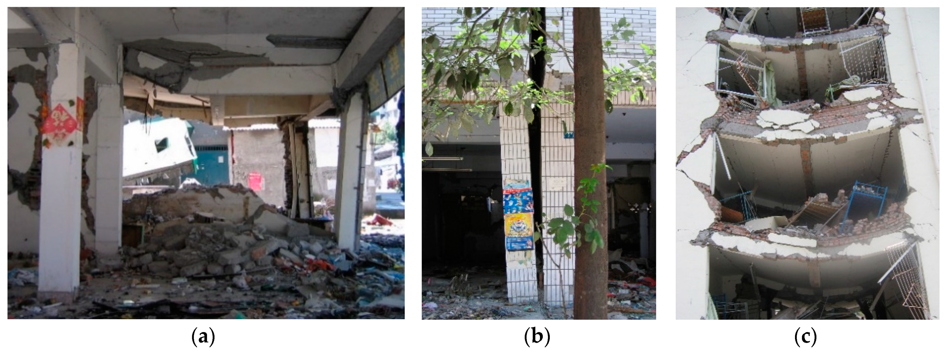
Figure 6.
Potentially vulnerable beam-column connections in an earthquake: (a) High-rise residential building in Hong Kong with irregular floor plan supported by reinforced concrete frame below a transfer plate structure; (b) low-to-medium-rise residential building in Melbourne supported by precast reinforced concrete columns at the ground floor forming soft- and weak-storey (photos were taken by the author).

Figure 7.
Proposed design of architectural bracket for upgrading or retrofitting building structures: (a) Schematic diagram of a bracket connected to a concrete structure using post-installed anchoring systems; (b) the external forces acting on the arch knee brace and the supporting circular ring.
Figure 7.
Proposed design of architectural bracket for upgrading or retrofitting building structures: (a) Schematic diagram of a bracket connected to a concrete structure using post-installed anchoring systems; (b) the external forces acting on the arch knee brace and the supporting circular ring.

Figure 8.
Arch knee brace: (a) Geometry and the x-y coordinate system; (b) comparison between the shape of quarter-circular, catenary and parabolic arches with the same rise.
Figure 8.
Arch knee brace: (a) Geometry and the x-y coordinate system; (b) comparison between the shape of quarter-circular, catenary and parabolic arches with the same rise.

Figure 9.
Schematic diagram of the contact conditions between supporting circular ring and structure: (a) Connection at a single point of contact; (b) connection through an enlarged area.
Figure 9.
Schematic diagram of the contact conditions between supporting circular ring and structure: (a) Connection at a single point of contact; (b) connection through an enlarged area.

Figure 10.
Required minimum thickness for different design seismic hazard level and span length of the arch knee brace (with constant width of 150 mm): (a) Fixed parabolic arch knee brace; (b) fixed semi-circular ring ().
Figure 10.
Required minimum thickness for different design seismic hazard level and span length of the arch knee brace (with constant width of 150 mm): (a) Fixed parabolic arch knee brace; (b) fixed semi-circular ring ().

Figure 11.
Design forces for a circular ring of different configurations and a range of contact conditions with the structure (represented by ): (a) Reaction force, ; (b) maximum bending moment, .
Figure 11.
Design forces for a circular ring of different configurations and a range of contact conditions with the structure (represented by ): (a) Reaction force, ; (b) maximum bending moment, .


Table 1.
Design parameters and section size of a fixed parabolic arch knee brace.
| (kN) | (mm) | (mm) | (kN) | (Nm) | (mm3) | (mm) | (mm) |
|---|---|---|---|---|---|---|---|
| 200 | 600 | 124 | 177 | 4971 | 9941 | 150 | 19.9 |
Table 2.
Design parameters and section size of a fixed semi-circular ring ().
| (kN) | (mm) | (mm) | (kN) | (Nm) | (mm3) | (mm) | (mm) |
|---|---|---|---|---|---|---|---|
| 200 | 600 | 73 | 81 | 1949 | 3897 | 150 | 12.5 |
© 2019 by the author. Licensee MDPI, Basel, Switzerland. This article is an open access article distributed under the terms and conditions of the Creative Commons Attribution (CC BY) license (http://creativecommons.org/licenses/by/4.0/).
Share and Cite
MDPI and ACS Style
Tsang, H.-H. Innovative Upscaling of Architectural Elements for Strengthening Building Structures. Sustainability 2019, 11, 2636. https://doi.org/10.3390/su11092636
AMA Style
Tsang H-H. Innovative Upscaling of Architectural Elements for Strengthening Building Structures. Sustainability. 2019; 11(9):2636. https://doi.org/10.3390/su11092636
Chicago/Turabian StyleTsang, Hing-Ho. 2019. "Innovative Upscaling of Architectural Elements for Strengthening Building Structures" Sustainability 11, no. 9: 2636. https://doi.org/10.3390/su11092636
Note that from the first issue of 2016, this journal uses article numbers instead of page numbers. See further details here.