Abstract
With the continuous progress of urbanization, the discharge of municipal solid waste has profoundly affected human production/living and social ecological health, and waste disposal has become one of the key issues all over the world. In the context of intelligent technology, this paper innovates the way of waste disposal according to the development direction of a smart city and the requirement of sustainable development strategy. An intelligent urban waste removal system is developed using a ROS (Route Operation System) robot operating system and RRT (Rapid Exploration of Random Trees) path planning algorithm. With a background of data management, the entire process of intelligent automatic waste removal is triggered by automatic communication from individual waste bins to a waste collection vehicle (WCV) where the bin needs to be emptied, and the automatic collection and transportation by the WCV in response. In combination with the IoT (Internet of Things), the system provides scientific data support for the intelligent layout of communities and even urban waste bins to greatly enhance the development of intelligence communities and smart cities.
1. Introduction
Cities are a product of the development of human civilization, and communities are their most fundamental element. As the carrier of the survival and development of urban residents, a smart community is the concentrated embodiment of the city’s overall smartness level, and this is a new concept of community management and a new model of social management innovation. It refers to a community that makes full use of the integrated application of the Internet of Things (IoT), cloud computing, mobile internet, and other new generation information technologies to provide a safe, comfortable, and convenient modern and intelligent living environment for its residents, thus creating a new-management form based on information and intelligent social management and service [1]. The main objectives of developing a smart community include providing sustainable and clean energy, offering good personalized medical services, and facilitating efficient data collection and analysis. With the continuous progress of urbanization, urban development focuses on not only the strategic issues e.g., spatial layout, traffic planning and regional development, but also the living environment and well-being of residents [2]. The continuous expansion of population brings tremendous pressure on resources and environment to the urban environment, and municipal solid waste, as a result, is growing at a rate of 5% to 10% every year [3].
Under the present situation of the increasing amount of city waste, the urban environmental capacity is far from satisfying the requirements of economic development, and the production of municipal solid waste in most cities has long exceeded their disposal and management capacity [4]. In addition, the shortage of municipal solid waste management funds and waste disposal equipment also makes it quite difficult to collect, transport and dispose domestic waste in an efficient and timely manner [5]. In this case, these domestic wastes are not collected and transported in time or they flow through the city, and they will have a negative impact on urban health and mental outlook [6] bringing potential harm to urban residents, and restricting the development of urban economy and the construction of smart cities and communities to a certain extent [7]. In this context, as an integrated problem in the fields of medical treatment, health, environment, ecology and psychology, municipal solid waste disposal has gradually become a popular research issue in the domain of smart communities/city construction [8].
The development of intelligent technology provides scientific support for the intellectualization of municipal solid waste cleaning [9]. Most previous research related to smart communities and smart cities, however, focuses on architectural analysis, such as architecture energy consumption and household medical data [10,11,12], and ignores research into infrastructure construction in the community. Waste collection, transportation, and disposal is a systematic process in the development of smart community infrastructure. Waste removal–the process of collecting and transporting waste from scattered points to the waste disposal site–is a high-cost link and also the key to connecting ‘up and down’ processes. Knowing how to manage this link effectively and improve its efficiency is of great significance in improving the current situation of waste removal in intelligence communities [13].
At present, research into waste removal mainly focuses on improving the function of waste bins, the location of collection points and transit stations, and the role of government and the public [14]. Studies normally pay more attention to optimizing a particular aspect of the collection and transportation system, with little interest in the whole system. From the perspective of smart city construction, knowing how to improve the urban waste management system (UWMS) has become an essential prerequisite for sustainable urban development, and waste removal is a central aspect, as its efficient technical optimization can obviously improve the operational efficiency of the whole system. That waste collection and transportation accounts for 60% of the total waste disposal system investment in Naples, Italy, for example, again indicates its importance [15]. Moreover, the general improvement in people’s living standards is resulting in the demand for a fresh and comfortable living environment becoming increasingly prominent, creating greater requirements for the removal and transportation of waste in the community.
The main contribution of this study is to propose an intelligent waste removal and optimal collection path mechanism based on RRT (Rapid Exploration of Random Trees) algorithm. Based on ROS (Route Operation System) robot operating system, the intelligent waste bin, the WCV (waste collection vehicle) and the background data management are integrated into a system, which realizes the one-stop operation of intelligent waste cleaning, simultaneously saving energy and human cost in removing waste. In order to verify the feasibility of the system, a closed park in Guangzhou, China is selected for simulation and testing, and a three-dimensional visual interface is independently built under the Gazebo simulation environment. The test results show that the system can select the optimal cleaning scheme through the capacity of the trash can, and identify and judge the surrounding environment in the process of movement. Compared with the traditional method, the application of this system can reduce the labor cost by 20%, and has more social benefits. To sum up, we have conducted an in-depth study on the intelligent waste disposal from the various aspects of theory, technology and social value. With the continuous development of 5G technology, this study has a great development prospect and can provide a powerful reference for infrastructure construction of smart communities and smart cities.
The remainder of this paper is arranged as follows: Section 2 reviews previous work involving smart communities and urban environmental governance, intelligent waste collection and transportation, the ROS operating system, and the path planning algorithm; Section 3 introduces the overall architecture of the system; while Section 4 presents the system implementation plan and simulation details. Case study and discussions are illustrated in Section 5 and Section 6. Section 7 concludes the research paper.
2. Literature Review
This section mainly reviews four aspects of smart communities and urban environmental governance, intelligent waste collection and transportation systems, the ROS operating system and path planning algorithms. In theory, we mainly focus on constructing intelligent community and application of technology in the system. At technical level, we briefly expound the principle of ROS operating system and RRT algorithm.
2.1. Smart Communities and Urban Environmental Governance
The smart city (community) refers to a new concept of community management and a new model of social management innovation in a new situation. With the help of the Internet and the IoT, it involves many fields such as intelligent buildings, smart homes, road network monitoring, personal health, and digital life, giving full play to the advantages of the developed information and communication industry (ICT), excellent telecommunication services, and information infrastructure. The construction of smart community originated in the United States. Due to the needs of urban development, the President of the United States Ronald Wilson Reagan announced the establishment of the Smart Housing Technology Cooperation Alliance in the 1980 s to test and standardize the residential intelligent technology, products and application systems, and guide new technologies for residential design and construction [16]. After that, the concept of intelligent community began to emerge in Europe, Japan, Southeast Asia and other regions of the world.
The development of technology provides strong support for the construction of smart community and smart city, such as the application of (1) UAVs (unmanned aerial vehicles) in intelligent transportation system [17], (2) artificial intelligence virtual platform in sustainable development [18], and (3) intelligent vehicle sensor network in self-driving [19], etc. In the process of urban development, environmental governance, as a difficult problem and breakthrough in the construction of a smart community and smart city, has aroused widespread concern from all walks of life. In the development process of intelligent environmental governance, environmental monitoring system is widely used in various cities to control the environmental state in real time [20]. Specifically, the construction of the smart community in New York solves the problem of urban waste disposal by building an intelligent social ecological network [21]. Yokohama, Japan introduces HEMS (Home Energy Management system) to visually analyze the amount of domestic waste produced in the community and the energy consumption of electrical appliances, and realize the effect of energy saving and emission reduction in the smart community through remote control and targeted treatment [22]. With the continuous increase of urban population and the deepening of smart community construction, the treatment of municipal solid waste has become an important issue in environmental construction. The research on intelligent treatment of municipal solid waste is not only carried out in developed countries, but has also gradually spread to other countries all over the world [23].
2.2. Intelligent Waste Collection and Transportation Systems
At present, the intelligent waste cleaning system basically takes the waste collection and transportation as the core, and establishes a comprehensive management system of classified collection and transportation and classified treatment for each type of waste [24]. At the technical level, the application of geographic information technology (GIS) and radio frequency technology (RFID) makes the management of a waste cleaning system more convenient, reduces manpower consumption and improves management efficiency [25]. Germany is the first country to apply radio frequency technology (RFID) to the area of intelligent waste cleaning, the relevant departments in charge of differential processing according to the identification results, and the use of sensors and image recognition technology to establish a dual-cycle cleaning system [26]. The American sanitation management agency advocates the use of intelligent methods to control the source of waste, using big data and the Internet of Things technology to automatically number urban waste bins, realizing the data visualization of each link of waste cleaning, and building an IWMS (Intelligent Waste Management system) [27]. In addition, China, Japan, Singapore, the United Kingdom, France and other countries have gradually applied intelligent technology to urban waste cleaning and developed intelligent cleaning systems suitable for their own development [28].
In the application of intelligent waste cleaning technology, Sarptas, H et.al. [29] studied the application of GIS technology in municipal solid waste planning and management. Arebey, M. et al. [30] take GIS, RFID, GPRS (General Packet Radio Service) and other technologies as the basic theoretical framework, install RFID tags on waste bins, install GPS, RFID readers on vehicles, and establish a monitoring system for waste production sites and collection vehicles through GPRS data transmission. With the advance of urbanization, the number and types of municipal solid waste have increased sharply, and waste disposal needs to develop in the direction of refinement step by step. In terms of subsequent waste disposal, Swapan Das. et al. [31] found the difficulty is partly due to the unscientific selection of the transportation route, which not only wastes workforce and material resources, but also causes financial losses as well as not complying with the principle of sustainable development. Additionally, as Ahumada et al. (2013) [32] point out, high population density, shortage of land, and traffic congestion lead to difficulties in the removal and transportation of municipal solid waste in central urban areas, suggesting that constructing a reliable waste transfer station in such areas involves considering such elements of external space as location, passageways, entrances, boundaries, signs, and peripheries. Zhang, H et al. point out that, by building a visual multi-objective transportation system, a scientific and rational collection route is the key to municipal solid waste removal [33].
2.3. The ROS Operating System
ROS 1.0 was developed by Willow Garage in 2010, followed by the official version of ROS Box Turtle. There have been more than a dozen ROS versions since. With the continuous expansion of ROS, a large number of ROS-based robots have entered the market, which has further promoted the development of ROS and higher requirements: its real time and stability need to be further improved. In response to the needs of the majority of researchers and future development, ROS 2.0 came into being in 2014, which added support for macOS and Windows platforms [34]. In 2017, the first official version of “Ardent Apalone”, code-named “ardent”, was launched. The aim of ROS 2.0 is to provide joint multi-robot control and cross-platform support, as shown in Figure 1 [35]. ROS 2.0 is based on the Data Distribution Service (DDS) middleware, which can realize the dynamic decoupling management of nodes in space and time, and significantly improve the fault tolerance and maintainability of the system [36].
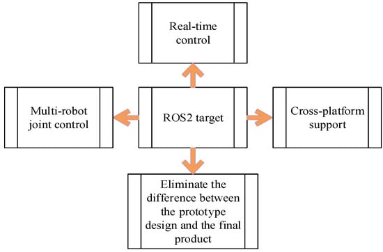
Figure 1.
ROS 2.0 implementation process diagram.
2.4. Path Planning Algorithms
Waste collection and transportation need a path planning algorithm. Optimal path planning is one of the leading contemporary topics in transportation and robotics, and many researchers have proposed algorithm improvements. Traditional path planning algorithms include simulated annealing, artificial potential field, fuzzy logic, and Tabu search. Intelligent optimization algorithms based on natural enlightenment and biological evolution include an ant colony, neural network, particle swarm optimization, and the genetic algorithm. Random search-based path planning algorithms such as Dijkstra algorithm, A* algorithm and RRT algorithm are often used in the construction of automatic systems. For the system developed in this study, a divergent algorithm, i.e., the Dijkstra algorithm, will automatically calculate the distance of the starting point to all the reachable points in the environment when solving the optimal path, which is useless and a waste of time for the system [37]. As a heuristic algorithm, A* algorithm will bring in a large number of duplicate data and complex evaluation functions. When the system does not need to solve the path length, the computational complexity of A* algorithm is large-not conducive to the operation and maintenance of technicians [38]. The two algorithms are thus not suitable for the path planning of this system.
As an effective data structure and sampling scheme, RRT algorithm can be used to quickly search high-dimensional spatial paths under algebraic constraints (caused by obstacles) and differential constraints (caused by nonholonomic and dynamic constraints) [39]. The main idea is to make the search tree expand towards the unknown space by collecting node samples in the state space [40]. The algorithm includes two stages, i.e., construction phase and path query phase. The construction process of RRT algorithm in EXTEND model is shown in Figure 2.
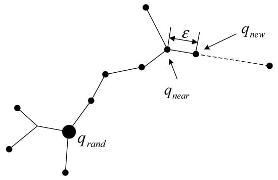
Figure 2.
The construction process of EXTEND.
As shown in Figure 2, a state is selected randomly in free state space, starting the RRT algorithm, finding the nearest vertex from according to distance measure. At this point, the function of the algorithm in algorithm acts on the , moving trajectory toward random state of moving a fixed distance , which contains collision detection function to determine whether new state (including intermediate state) satisfies global constraints. If the NEW-CONFIG function can be executed successfully, a new state of will be then obtained. Path planning based on RRT algorithm needs to repeat these processes and finally select optimal scheme by comparison [41].
As RRT path planning involves random sampling, its search speed is fast because it does not need to deal with the state space in the system. Moreover, it is not limited to solving high-dimensional constrained space problems, and is therefore often used in the construction of automatic systems path planning [42]. In the field of automatic systems, the RRT algorithm has become a conventional technology to solve the single query motion-planning problem. In agricultural production, the improved RRT algorithm can solve the obstacle avoidance problem of a litchi fruit picking robot in a dynamic and unstructured environment [43]. In the field of large-area detection, the RRT algorithm can quickly converge on the shortest path by reducing the time and storage requirements needed, so that the model is robust and effective [44]. In the field of high collision manipulation, the RRT algorithm can reduce the sampling area of free configuration space by extending the forward tree and backward tree and introducing N-dimensional cube region dynamics [45].
The RRT algorithm is suitable for a dynamic environment due to its probabilistic completeness, fast reprogramming, and easy to integrate all kinds of constraints [46]. It has been widely used in robots, UAVs (unmanned aerial vehicles), intelligent wheelchairs, and even the shipbuilding industry. Furthermore, with the continuous development of artificial intelligence technology, the application of the algorithm to the construction of smart infrastructure will facilitate further development of the smart city. In short, the RRT algorithm does not need to model the environment when planning the path and is adaptable to dynamic scenes. It avoids spatial modeling through its collision detection of sampling points in state space, can quickly and effectively solve the problem of path planning in high-dimensional space with complex constraints, and guides the search to the blank area by random sampling points in the state space. Its suitability for the path planning of multi-degree-of-freedom robots and self-driving vehicles in complex and dynamic environments means it can be well adapted to the waste removal path planning of a smart community.
3. Overall Architecture of the System
This system has both an automatic mode and manual mode. The automatic mode is the primary research description and discussion in this paper.
When the system chooses manual mode, it can be manipulated manually to deal with unexpected problems more pertinently. In this study, we only list the extension modules that can be selected, but do not carry out a specific design. For example, we can flexibly choose the cleaning mode in the manual mode, and sometimes, we do not just consider the optimal path problem. Manual operation is required when many aspects need to be considered. The unmanned floor sweeper mode is set to make better use of the free time of the WCV. When the waste bin does not need to be cleaned, the car can be equipped with a sweeping device to clean up the road. The artificial model can also expand more intelligent modules, as long as it is in line with social feasibility, technical feasibility and economic feasibility.
The default boot mode of the system is automatic, involving an intelligent waste bin equipped with a capacity sensor, to detect the amount of waste in real time. When the amount of waste exceeds a preset threshold, it summons the intelligent WCV to empty it. However, the process of waste disposal is not limited to waste bins that exceed the threshold. When the WCV is in range, the optimal benefit module guides it to the nearby waste bin to collect its waste. Then, it returns to the waste transfer station and prepares for the next removal task. Figure 3 provides the system’s flow chart.
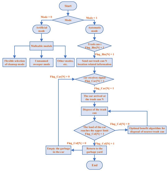
Figure 3.
Schematic diagram of the system mode selection.
In the flow chart, Flag_ bin [N] = 1 indicates that the capacity of the trash bin numbered N reaches the set value and waste disposal needs to be carried out. Flag_ [N] = 1 indicates that the WCV is receiving the signal and performing a task. Flag_ [N] = 0 means that the WCV has completed the cleaning task and can be arranged in the next step. Flag_ Coll [N] = 1 indicates that the WCV load reaches the upper limit and should go to the waste transfer station to empty the waste inside. Flag_ Col0 [N] = 0 means that the WCV has been emptied.
3.1. Disadvantages of the Traditional System Architecture
The most common currently used tool in software development work is embedded software architecture. However, this has many algorithms and testing problems that need to be improved and optimized. As Zhen Peng points out, the performance and efficiency of embedded software architecture tends to decline in most applications, which delays the software development cycle [47].
This can be overcome, to some extent, by using embedded software component library ORES in a tool environment to support the semi-automatic component assembly and analysis of the non-functional attributes of the whole system by the code template method. However, there are still many disadvantages in the use of global variables [48]. Thus, a customizable real-time component framework has been proposed, including customization methods and related support tools. As the hierarchy of the framework is unstable and prone to inefficiency [49], a tool chain was developed that supports the real-time design and analysis of the software components [50]. However, the integration testing of a single tool chain is very challenging [51]. In order to solve this problem, technicians have constructed a set of visual software development environment. Developed in 2008, this is based on the component-based embedded real-time operating system, Tiny-OS, which can automatically assemble components and generate code visually [52]. The accuracy of the system is not enough, however, and still needs constant optimization to achieve the desired results. A verifiable embedded real-time software framework development environment, VERTAF, was proposed in 2004. This adopts component technology, formal synthesis technology, and verification technology, and uses the real-time component model, ERTO, to implement real-time applications [53]. Starting from the system model UML, it automatically carries out model transformations, scheduling, code generation, and system verification. VERTAF can flexibly add new tools and algorithms to improve itself [54]. Even so, when using the model, it is easy to cause an abnormal response of the system if the calculation of a specific algorithm sub-module is abnormal or timed out.
3.2. Framework Optimization and Improvement
The proposed system architecture illustrated in Figure 4 is characterized by high reliability, high modularization, high operating efficiency, and high definition of the structure; meets the requirements of individual testing of each module and the automatic testing of the whole system; and avoids the use of global variables between modules and the exception of a single algorithm.
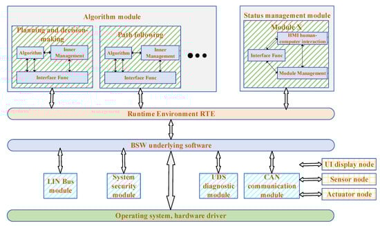
Figure 4.
Schematic diagram of the system embedded software architecture.
Here, the embedded software architecture can implement relatively independent algorithms and divide the logic set into a system module. Its input and output are evident, including the internal management logic, algorithms, and interface function. Moreover, there is no direct interaction between the module and the underlying modules, and the global variable is no longer used. All data transmission is implemented using interface functions defined in RTE, which is mainly responsible for the initialization and assignment of the interface function [55]. The module can obtain the corresponding variable data by calling the interface function.
The function of the system is composed of a state management module and a plurality of algorithm function modules. The state management module is responsible for computer interaction and module management, and the function interface module only allows the use of discrete signals and state quantities, thus ensuring the independence and testing ability of the logic. The embedded porting or simulation testing only needs to ensure that its running time sequence and RTE data are updated correctly and do not need to configure any functions, which reduces the coupling of the system and facilitates its overall testing.
3.3. Benefits of the Improved Architecture
Although the traditional system architecture has many shortcomings, after further optimization and improvement, the algorithm independence and running efficiency of the system has been greatly improved.
First, the improved architecture has a stable communication mechanism, which can realize the fast and effective information exchange between the automatic WCV, waste bin, and background-monitoring center. The system adopts distributed architecture, realizes the hierarchical operation of message transmission tasks through independent nodes, reduces the pressure of real-time computing, and can provide a convenient hardware driver interface for robots and sensors. The distributed architecture system is divided into three entities, i.e., node, network and storage. Technicians can connect to the network and realize storage through external interfaces, which means that successful external cases can be cited to supplement and improve the system [56]. It dramatically reduces the difficulty and complexity of the development of the unattended sweeper system, and contributes to the expansion and maintenance of the system functions. In addition, the distributed architecture system has the characteristics of easy development, few faults and clear structure [57]; it thus can integrate students from different directions and fields to participate in design and research, which helps increase the development of the whole system.
Second, the core technology of the system is in enabling an automatic WCV to carry out autonomous navigation movement according to the interaction of information. This technology carries out the modeling and simulation verification of the system as described in the next section, where the module is tested in the field environment. It includes sensor fusion positioning tests and object recognition based on computer vision, which verifies the feasibility of the autonomous navigation of automatic WCVs in a specific operating area. Moreover, the system can accurately dock the waste bin with the WCV through a magnetic strip at the bottom of the bin by the accurate exchange of information between the bin and WCV.
Finally, the system is developed based on the ROS robot operating system. ROS has strong code reusability and hardware general performance [58]. By adopting distributed architecture, each node with an independent function can realize the hierarchical operation of message transmission tasks, and reduce the pressure of real-time computing. The system can also provide a very convenient hardware driver interface for commonly used robots and sensors, which significantly reduces the difficulty and complexity of its development, and facilitates the later expansion and maintenance of its functions–enhancing the feasibility of the development of the whole system.
4. System Implementation Plan and Simulation
This part first introduces the internal structure and workflow of the system, and then makes an in-depth introduction to the three major components of the system, i.e., BIN unit, CAR unit and information interaction unit. The BIN unit mainly includes three functions: status escalation, overflow self-test and waste collection. The CAR unit is mainly composed of three modules: environment awareness and location, planning and decision, and collision detection and avoidance of path obstacles. The information interaction unit is mainly responsible for processing the data and outputting the best waste removal route as well as the deployment suggestions for all relevant parts of the system.
4.1. Internal Structure of the System
The system is divided into three units–the unit, unit, and background management unit.
The unit uses a calibrated ultrasonic sensor for waste overflow detection. When there is no waste in the waste bin, the ultrasonic sensor feeds back the amount of waste as: , the unit receives the signal “” from the interaction unit, and the WCV waits automatically. When the amount of waste is more than 80%, the signal “” is displayed (the default threshold value), the unit receives an interactive signal: , and sends the coordinate information and other useful signals of the unit to the background management unit, which sends the signal “” to the unit. The WCV unit carries out a series of operations, such as perceptual fusion, planning decision making, obstacle avoidance detection, path following, and motion control. When the WCV successfully reaches the preset target position and posture according to the planned path and confirms in the background snap-in that the WCV successfully matches the waste bin (Check = 1), the unit control module controls the waste disposal by transferring the waste to the WCV to complete the task (Task = 1). Then, the WCV returns to the waste transfer station according to the default path to complete a waste removal process.
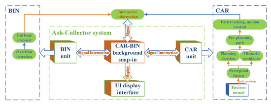
Figure 5.
Schematic diagram of the system structure.
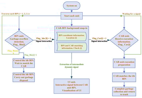
Figure 6.
Schematic diagram of the system workflow.
The entire automatic collection system is based on the ROS communication architecture. As a relative robot operating system, ROS is very suited for use in automatic systems. It has strong code reusability and hardware general performance, and it adopts distributed architecture for the hierarchical operation of messaging tasks through each functional independent node to reduce the pressure of real-time computing. Moreover, it can provide a very convenient hardware drive interface for commonly used robots and sensors, and significantly reduce the difficulty and complexity of the development of automatic vehicle collection systems.
4.2. The BIN Unit Function
Intelligent waste bin built-in sensors, such as ultrasonic sensors and odor sensors, are used to detect the remaining bin capacity, waste odor, and other information to provide data source for the entire regulatory system and the amount of waste to be collected to ensure timely waste removal, odor detection, and ultraviolet sterilization to ensure urban environmental hygiene. When the BIN unit monitors an abnormal state, the corresponding data is sent to the CAR-BIN background management unit through the LoRa communication module for analysis and the proposal of any corresponding countermeasures. The following subsections describe the status reporting module, overflow self-checking module, and waste collection module.
4.2.1. Status-Reporting Module
The status-reporting module refers to the regular reporting of the working status of the waste bin. The smart waste bin can produce a real time clock (RTC) alarm interruption every other hour to wake up the kernel into the main program and check whether each module is working correctly. Then the LoRa communication module starts and transmits the test results to the cloud data center. Finally, the STM32 chip enters stop mode again. The schematic diagram of the status-reporting module is shown in Figure 7.
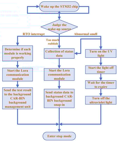
Figure 7.
Schematic diagram of the status-reporting module.
4.2.2. Overflow Self-Test Module
Based on the performance of the ultrasonic sensor, which can propagate in gas, liquid, solid, and other media, the ultrasonic detection method is adopted in the BIN unit waste overflow detection device. A schematic diagram of the principle of ultrasonic detection is shown in Figure 8.
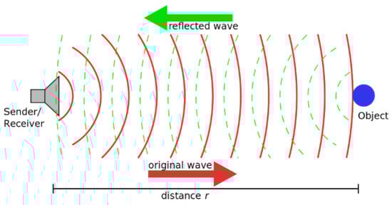
Figure 8.
Schematic diagram of the principle of ultrasonic detection4.2.3. Waste collection module.
4.2.3. Waste Collection Module
The automatic waste collection steps are as follows:
- (1)
- When the WCV arrives at the waste bin, the system uses the automated parking technology to park it in a designated location matched with the waste bin, whereupon the spring clamp mechanism locks the bin’s top edge onto the WCV guide rail through its spring tension – the bottom support of the waste bin bearing the weight of the bin.
- (2)
- The bin is then powered up the guide rail, with its lid being opened by an automatic switch operated by the bin’s rise. Upon reaching the dumping window, the waste is dumped, with the bin’s lower edge protruding part limiting its posture to ensure accuracy.
- (3)
- The process is then reversed, with the bin lid closing automatically by compressing the reset spring of its automatic switch device under the action of gravity.
The Flow chart of the process is illustrated in Figure 9.
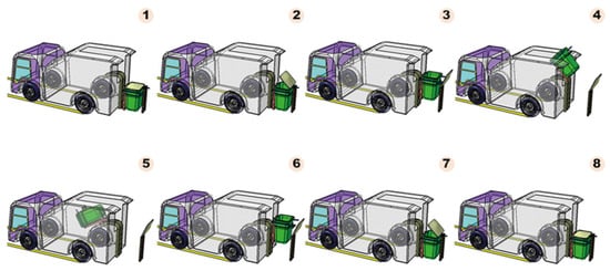
Figure 9.
Flow chart of waste dumping.
4.3. The CAR Unit Function
4.3.1. Environment Awareness and Location Module
Environment awareness and location function refers to the process of identifying and dealing with the surrounding environment of the WCV during the operation of the system. In the working state, the WCV needs to feedback its positioning and environmental information in real time through intelligent technology to assist the background for state control and emergency handling. For example, when there is an obstacle to the function of the WCV, the manager can quickly determine its location according to its location information and deal with it accordingly.
Perception is an essential part of the system design because it cannot work correctly without the quantitative perception of the three-dimensional environment around the WCV. The automatic WCV uses light detection and ranging technology (LiDAR), ultrasound, and camera sensors to sense the environment. Of these, LiDAR uses SLAMTEC RPLiDAR-S1, which is an outdoor LiDAR, can resist intense light, has a detection distance of up to 40 m, a sampling speed of 9200 times/s, and a scanning frequency of 15 Hz. It can carry out 360° omni-directional scanning to range the detection of the surrounding environment and obtain an outline map of the surrounding environment, which can be used to scan the whole environment space involved. Through the cartographer algorithm, the environmental data points scanned by the laser are integrated, and a high-precision 2D LIDAR viewing angle map constructed based on the particle filter algorithm is used to track the WCV’s position. The ultrasonic sensor has a US−100 ultrasonic ranging module with a non-contact ranging function of 2 cm–4.5 m that can be used to assist the WCV avoid obstacles. The two-dimensional images captured by the camera can be used to infer physical information of the three-dimensional world as well as identifying the waste bin and confirming the collection point’s location [59]. The automatic WCV is implanted with an IMU + encoder and IMU + GPS positioning system to control its positioning accurately.
The positioning of the odometer is made by the IMU + encoder, in which the IMU uses a GY−85 nine-axis degree of freedom sensor. The angle and acceleration information (measured by the IMU) and the velocity information (measured by the encoder) are fused by an extended Kalman filter to track the WCV, which effectively reduces mileage drift. The GPS positioning module uses a Qianxun RTK decimeter class GPS/Beidou module with 1 Hz frequency and positioning accuracy at the decimeter level. The lossless Kalman filter fusion of the angle and acceleration information measured by the IMU and the output data information of the GPS/Beidou module is intended to compensate for the excessive positioning cycle of the GPS and render the sweeper positioning more accurate.
4.3.2. Planning and Decision Module
The system uses the memory tracking path planning algorithm, and the normal driving route of the actual WCV is saved as the reference path for application [60]. In local path planning, a directed particle is defined, whose initial pose is , and terminal pose is . The parking path planning algorithm refers to the actual motion law of the vehicle combined with the principle of plane geometry and the optimization method, and plans the path that avoids the interference of obstacles. It is assumed that the initial directed particle moves as the Ackerman mechanism with curvature ρ [61]. The path planning algorithm used here is shown in Figure 10.
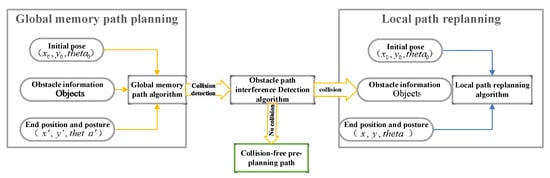
Figure 10.
Path planning algorithm.
4.3.3. Collision Detection and Avoidance of Path Obstacles
A path obstacle collision detection algorithm suitable for the path planning module is proposed, considering its real-time and reliability characteristics.
- (1)
- Path and obstacle representationAs shown in Figure 11, any path trajectory, traj, is represented by five parameters of , where is the starting position of the WCV corresponding to the path, is the length of the path, and is the radius corresponding to the path ( > 0 means the left turn of the WCV, < 0 means the right turn of the WCV, and = 0 means the WCV is driving in a straight line). With this method, any obstacle, obj, is represented by a line segment, which is described by two endpoints and .
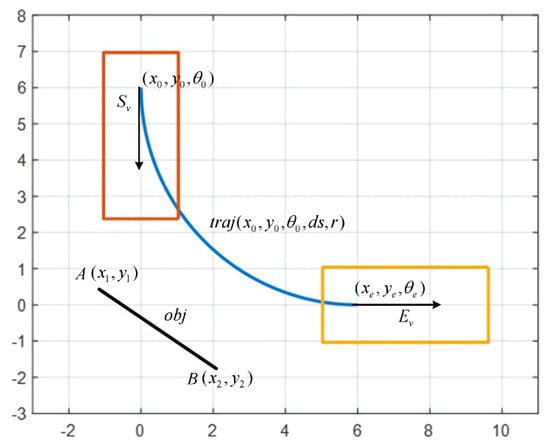 Figure 11. Schematic diagram of paths, obstacles, and WCV profiles.In the process of collision detection, the outline of the WCV is simplified to a rectangle. Obstacle collision is detected according to the path contour, i.e., the boundary contour formed by the WCV driving along the specified path from the starting position to the end position [62]. According to the size of , the detection is divided into arc-path-obstacle-collision detection and straight-line-path-obstacle-collision detection [63].
 - (2)
- Collision detection of arc path obstaclesFigure 12 is a schematic diagram of the parameters of arc-path-obstacle-collision detection, which shows the path and obstacle parameters that need to be used.
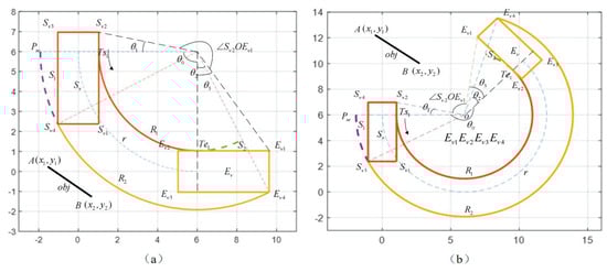 Figure 12. Schematic diagram of the collision detection parameters of arc path obstacles. (a) shows the path collision detection parameters before the obstacle is encountered, (b) shows the path collision detection parameters after the obstacle is encountered.
 - (3)
- Collision detection of obstacles in a linear path
- (4)
- For the collision detection of obstacles in a straight path, the WCV profile can be simplified to a rectangular . Collision detection can then be carried out according to whether the obstacle segment interferes with the rectangle, as shown in Figure 13.
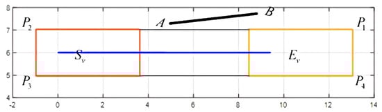 Figure 13. Schematic diagram of collision parameters of a linear trajectory obstacle.
4.4. Information Interaction Unit Function
The information interaction module can realize the information interconnection of the intelligent waste bin, WCV bin-background management unit, and automatic WCV, with LoRa low power WAN technology–a new generation of wireless communication technology–used for information exchange between the three. This technology has the advantages of low power consumption, long-distance, anti-interference, high sensitivity, and low cost.
The information interaction module involves bin-background information interaction, background-WCV information interaction, and a background-sanitation management center. Bin-background information interaction is mainly responsible for responding to all kinds of abnormal data reported by the LoRa communication module; background-car information interaction is responsible for analyzing the historical state information and deployment location of the waste bin and sending the location information and the best driving route through the LoRa communication module to the nearest automatic WCV. The background-sanitation management center is responsible for sending the data, i.e., the waste deployment recommendations, waste station deployment recommendations, and automatic WCV location deployment recommendations to the sanitation management center for decision-making. The whole process is shown in Figure 14.
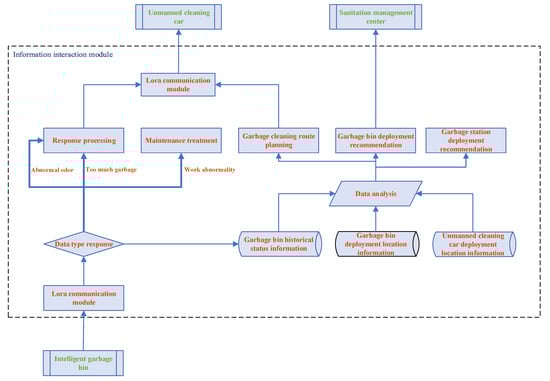
Figure 14.
Framework diagram of working principle of information interactive unit.
When the information interaction module receives the status data uploaded by each intelligent waste bin, it first judges the data type. If this is the standard working status data of the waste bin, it updates the working status table, while if this is abnormal state data, it will be processed according to the abnormal state type, and the waste bin abnormal state table in the database will be updated.
From the historical status information of the waste bin, the deployment suggestion of the waste bin, the location deployment suggestion of the automatic WCV, and the best deployment suggestion of the waste station can be made, which provides the decision-making reference for the sanitation management center. Based on the waste quantity and recovery time data of each waste bin, a waste-quantity change curve is obtained. Then the weight polling scheduling algorithm is used to locate the waste bins with rapid waste growth and need for frequent recycling and then obtain deployment suggestions for any additional waste bins. Based on the average waste generation rate and geographical location information of each waste bin, the optimal waste-station deployment plan is calculated by the K-MEANS algorithm.
The waste accumulation and geographical location information of all the waste bins in the region are abstracted into a waste bin distribution map [64], and the shortest traversal path calculated by using the simulated annealing algorithm: this is the best waste removal route. The analysis provides location information of the waste bins that need to be emptied and optimal route to the WCV by the LoRa communication module [65] to start the automatic collection process.
5. Case Study
The system was demonstrated and tested in a closed park in Guangzhou, China. The park area is 26,640 m2, the building coverage area is 18,707 m2, and the green coverage rate is 8%.
5.1. LiDAR Mapping Test and Simulation
Figure 15 shows the test monitor used for the test, and the RPLIDAR-S1 LiDAR result map obtained.
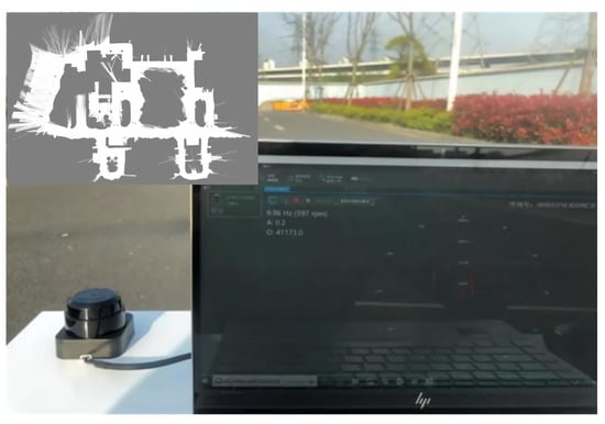
Figure 15.
Outdoor campus environment test and result map.
Under the Gazebo simulation environment, a 3 D simulation environment of the campus was independently built. The simulation model loads the RPLIDAR-S1 LiDAR sensor, and the relevant parameters are set. In the simulation environment, the model is used to control the movement of the WCV and completes the 3D scanning and mapping work to create the effect picture. The whole process is shown in Figure 16.
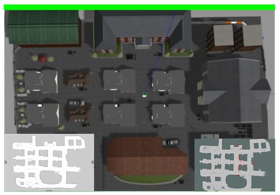
Figure 16.
Simulation environment and scan map.
5.2. IMU and GPS Fusion-Positioning Test
The data sources used in the sensor fusion-positioning test of the automatic WCV are Qianxun RTK decimeter GPS/Beidou module positioning data (1 Hz frequency), and the IMU poses data (10 Hz frequency). The original GPS positioning data and fusion-positioning data are converted into longitude and latitude format and marked on the Baidu map [66], and the trajectory of positioning data is compared. The test route of the WCV and the associated positioning data collected are shown in Figure 17.
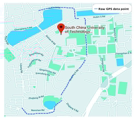
Figure 17.
GPS original positioning data map.
Amplifying the GPS signal showed that the original GPS positioning data are blocked by trees or buildings in some road sections, resulting in signal discontinuity or signal loss [67]. Although the signal was not completely blocked in some road sections, the signal location drifted to some extent, as shown in Figure 18.
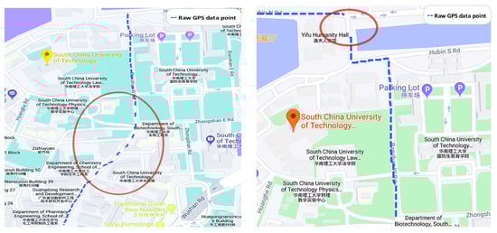
Figure 18.
Sample diagram of the signal drifts.
The data fusion positioning results based on the UKF (Unscented Kalman Filter) are shown in Figure 19 and Figure 20, showing that the overall positioning trajectory matches the planned route. As the route planning algorithm of the Baidu map is not gently processed, the route at the corner is different from the actual trajectory [68]. The fusion positioning results show that the system can genuinely reflect the driving position of the test WCV.
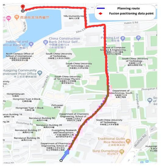
Figure 19.
Result map of fusion location.
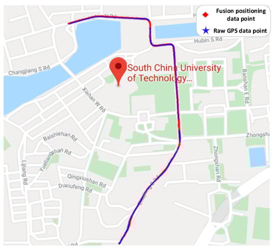
Figure 20.
Result of data fusion compared with the original GPS data.
Comparing the data fusion results with the GPS original positioning data indicates the fusion results are not distorted, and counteract the shortcomings of the excessive GPS positioning cycle-the data output frequency of data fusion positioning is 20 Hz and the fusion result is smoother than the original GPS positioning. The system’s use of other sensors for positioning therefore allowed data fusion to effectively solve the problem of GPS signal loss caused by building or tree occlusion, correct the impact of GPS signal drift, and smooth the positioning trajectory.
5.3. Path Planning Test in the Simulation Environment
The campus simulation environment is built based on Gazebo, and the simulation tests were carried out for path planning and navigation. The introduction of the function of the simulation platform mainly includes the working mode, real-time status, cleaning process, cleaning progress and the simulation display of the corresponding environment. When the system receives the waste disposal reminder signal, the path planning process is carried out. After reasonable path planning, the automatic WCV arrives at the waste bin. When the automatic WCV test is fully loaded, it will be automatically returned to the waste transfer station. The whole process is shown in Figure 21.
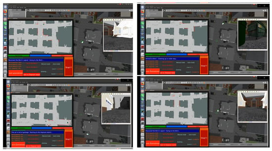
Figure 21.
4. Target detection in the simulation environment.
5.4. Target Detection in the Simulation Environment
In this system, the automatic WCV is endowed with machine vision so it can identify and judge the surrounding environment in the process of moving. Target detection is made by the YOLO algorithm, which has the advantages of high speed, strong robustness, and high accuracy [69]. It can perceive the environment around the WCV in real-time and report it to the background data management center. The effect of the system is shown in Figure 22.
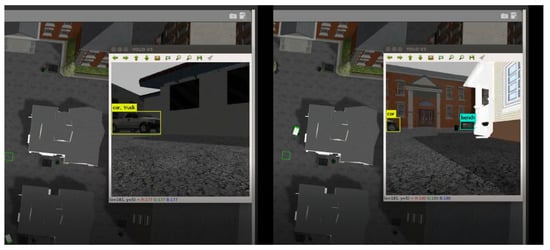
Figure 22.
Implementation inspection map of the surrounding environment.
5.5. Comparative Cost Analysis
This section conducts a cost analysis of the system in comparison with traditional methods. It is assumed that the energy consumption and maintenance costs saved by the system are equal to the sum of the operation and maintenance costs of the equipment and the energy consumption of the management terminal, while the labor cost is reduced by 20%. The labor cost is CNY 2500/month (according to a survey conducted by South China University of Technology on 28 November 2019, the average driver is responsible for collecting 40 waste bins).The cost of each component of the system is shown in Table 1 below.

Table 1.
Equipment costs.
According to this assumption, the monthly labor cost saved in the operation phase of the system is 2500 × 28/40 × 0.2 × 1 = CNY 350, and the static payback period is 3862.6/350 = 11.04 months. The waste removal costs of a university within the scope of the experiment can therefore be reduced by CNY 350/month, which means the transformation cost can be recovered in approximately 11 months for this site.
To sum up, according to the concept of sustainable development of smart community construction, the establishment and use of the system will significantly promote the construction of a creative community, the development of intelligent technology, and save operating costs – in the case of educational establishments such as this case study, enabling increased investment in learning and teaching resources.
5.6. Comparative Analysis
We have compared the development system of our institute with existing waste disposal devices on market, as shown in Table 2. Positioning accuracy indicates the ratio between number of times and starting times of the device arriving at a certain position in the same environment. Cleaning effect indicates a ratio of waste collection to total waste amount in the same environment. Cost represents the sum of prices constituting all parts of the device.
Table 2.
Comparison of various cleaning systems *.
According to comparison results, it is found that the system developed in this research is superior to other cleaning devices on the market regarding positioning accuracy, sensitivity and cost. Furthermore, it can increase or reduce corresponding functions according to the demand in future.
6. Discussions
At present, although there are many new intelligent ways to collect and deal with community waste (e.g., automatic sweepers, intelligent floor sweepers, and intelligent waste bins), they focus only on a specific aspect and do not involve any systematic innovation. For example, although the body of the waste bin has been intelligently modified (e.g., with voice prompt and smell detection functions), it has not yet constituted a component of an automatic waste removal system-making it impossible to automate the whole process of intelligent waste removal in the community [70].
In developed countries, managing municipal solid waste disposal is more mature. However, most research into municipal waste sensing and collection devices is confined solely to the intelligent aspects of the waste bins instead of the overall system. In 2016, the Big-Belly-Solar Company of the United States launched a smart waste bin that integrates solar energy, IoT, and high-efficiency compressors. However, its use is greatly limited by its high unit price (approximately USD 8000) [71]. Finnish Enevo Co., Ltd. launched EnevoOneCollect smart waste bins based on wireless sensing and cloud services technology, aiming to “travel less and recycle more waste” [72]. These attempts are mainly aimed at the sensing, collection, and classification of waste. In Sweden in 2017, Volvo also launched a trial operation of automatic waste collection vehicles (WCVs) (also variously known as refuse trucks, dustcarts, rubbish trucks, junk trucks, bin wagons, dustbin lorries, bin lorries, bin vans, and trash trucks.) using mechanical grippers to grab and dump waste bins [73]. However, the WCVs still had to be driven manually.
To solve this in an environmentally sustainable way, this study develops an automatic community intelligence waste removal system based on the RRT path planning algorithm, ROS operating system, and sensor intelligent deployment technology, with the functions of automatic waste removal, perception of big data, and the IoT. This study makes a pioneering innovation in the form of waste treatment in theory, and uses intelligent algorithms to reconstruct and reproduce the traditional form of waste treatment. This helps realizing the systematization and integration of waste treatment in a real sense. At the practical level, the intelligent waste disposal system developed in this study not only saves social costs and improves efficiency, but also helps to promote the construction of smart cities.
7. Conclusions
Based on RRT path planning algorithm and ROS robot operating system, an intelligent operating system for the whole process of waste disposal is developed.
At the technical level, the algorithm optimization and innovation of the traditional system architecture model are conducted, and the whole process of waste disposal is automated and intelligent. At the theoretical level, it improves the intelligent scheme of waste disposal in the structured scene of the city, and provides a reference for infrastructure construction of smart communities and smart cities. At the practical level, taking a university in Guangzhou as a case study and on the basis of ensuring the maneuverability of the system, conclusions are drawn that the cost of waste disposal can be effectively saved.
In the future, the system can also be improved according to the requirement, for example, the existing system can be optimized by using advanced technology to improve the positioning accuracy of the system and strengthen the background data processing mechanism. In further research, we can also try to develop the night cleaning function of the automatic WCV, and assemble a camera to realize the patrol function while cleaning, and realize the development and application of the multi-function system. The application of intelligent technology in the future will be diversified, which not only makes people’s lives more convenient, but also makes communities and cities smarter. In the context of some new technologies such as 5G and artificial intelligence, this system will have a broad room of optimization and development prospects.
Author Contributions
Data curation, Q.Z.; Conceptualization, Q.Z.; Formal analysis, Q.Z.; Data curation, Q.Z.; Funding acquisition, H.L.; Investigation, Q.Z. and H.S.; Methodology, Q.Z. and H.L.; Project administration, Q.Z.; Resources, Q.Z.; Software, Q.Z.; Supervision, Q.Z.; Validation, Q.Z. and H.S.; Visualization, Q.Z.; Writing—original draft, Q.Z.; Writing—review & editing, Q.Z., H.S., H.L., X.W. and M.S. All authors have read and agreed to the published version of the manuscript.
Funding
This work is supported by National Natural Science Foundation of China (grant numbers71501074, 71802071); the “13 th Five-Year” Plan of Philosophy and Social Sciences of Guangdong Province (2019 General Project) (project number GD19CGL27); the State Key Laboratory of Subtropical Building Science, South China University of Technology, China (2020ZB17); the Youth Project of Humanities and Social Science Fund of Ministry of Education of China (grant number 18YJCZH166); the Fundamental Research Funds for the Central Universities (approval number 2019MS116; project number x2tj/D2192640); and the Fundamental Research Funds for the Central Universities (grant number B200202044).
Conflicts of Interest
The authors declare no conflict of interest.
References
- Kazmi, S.H.A.; Abid, M.M.; Iqbal, M.; Hai, L.C. Impact of cloud services to the economic growth. In Proceedings of the IEEE International Conference on Cloud Computing and Big Data Analysis (ICCCBDA), Chengdu, China, 5–7 July 2016; pp. 268–272. [Google Scholar] [CrossRef]
- Han, M.J.N.; Kim, M.J. Green environments and happiness level in housing areas toward a sustainable life. Sustainability 2019, 11, 4768. [Google Scholar] [CrossRef]
- Withanachchi, S.S.; Kunchulia, I.; Ghambashidze, G.; Al Sidawi, R.; Urushadze, T.; Ploeger, A. Farmers’ perception of water quality and risks in the Mashavera River Basin, Georgia: Analyzing the vulnerability of the social-ecological system through community perceptions. Sustainability 2018, 10, 3062. [Google Scholar] [CrossRef]
- Ghesla, P.L.; Gomes, L.P.; Caetano, M.O.; Miranda, L.A.S.; Dai-Prá, L.B. Municipal solid waste management from the experience of São Leopoldo/Brazil and Zurich/Switzerland. Sustainability 2018, 10, 3716. [Google Scholar] [CrossRef]
- Singh, A. Managing the uncertainty problems of municipal solid waste disposal. J. Environ. Manag. 2019, 240, 259–265. [Google Scholar] [CrossRef]
- Yang, H.; Huang, X.; Thompson, J.R.; Flower, R.J. Chinese landfill collapse: Urban waste and human health. Lancet Glob. Heal. 2016, 4, e452. [Google Scholar] [CrossRef]
- Henriksson, G.; Åkesson, L.; Ewert, S. Uncertainty regarding waste handling in everyday life. Sustainability 2010, 2, 2799–2813. [Google Scholar] [CrossRef]
- Kumar, A.; Samadder, S.R. A review on technological options of waste to energy for effective management of municipal solid waste. Waste Manag. 2017, 69, 407–422. [Google Scholar] [CrossRef] [PubMed]
- Mian, M.M.; Zeng, X.; Nasry, A.A.N.B.; Al-Hamadani, S.M. Municipal solid waste management in China: A comparative analysis. J. Mater. Cycles Waste Manag. 2017, 19, 1127–1135. [Google Scholar] [CrossRef]
- Zavadskas, E.K.; Cavallaro, F.; Podvezko, V.; Ubarte, I.; Kaklauskas, A. MCDM assessment of a healthy and safe built environment according to sustainable development principles: A practical neighborhood approach in vilnius. Sustainability 2017, 9, 702. [Google Scholar] [CrossRef]
- Ferrández-Pastor, F.J.; Mora, H.; Jimeno-Morenilla, A.; Volckaert, B. Deployment of IoT edge and fog computing technologies to develop smart building services. Sustainability 2018, 10, 3832. [Google Scholar] [CrossRef]
- Park, S.; Lee, S.; Park, S.; Park, S. AI-based physical and virtual platform with 5-layered architecture for sustainable smart energy city development. Sustainability 2019, 11, 4479. [Google Scholar] [CrossRef]
- Gott, M.; Steinbach, J.; Mamat, C. The radiochemical and radiopharmaceutical applications of radium. Open Chem. 2016, 14, 118–129. [Google Scholar] [CrossRef]
- Van Houdt, B. On the power of asymmetry and memory in flash-based SSD garbage collection. Perform. Eval. 2016, 97, 1–15. [Google Scholar] [CrossRef]
- Ahmed, M.; Scerbo, M.; Izzo, P.; Parrilli, M.; Coccia, F.; Ganga, V.; Anilir, S. A community-based waste management system for the historic centre of Naples. J. Asian Archit. Build. Eng. 2009, 8, 363–370. [Google Scholar] [CrossRef][Green Version]
- Maalsen, S. Smart housing: The political and market responses of the intersections between housing, new sharing economies and smart cities. Cities 2019, 84, 1–7. [Google Scholar] [CrossRef]
- Menouar, H.; Guvenc, I.; Akkaya, K.; Uluagac, A.S.; Kadri, A.; Tuncer, A. UAV-enabled intelligent transportation systems for the smart city: Applications and challenges. IEEE Commun. Mag. 2017, 55, 22–28. [Google Scholar] [CrossRef]
- Duan, L.; Lou, Y.; Wang, S.; Gao, W.; Rui, Y. AI-Oriented Large-Scale Video Management for Smart City: Technologies, Standards, and beyond. IEEE Multimed. 2019, 26, 8–20. [Google Scholar] [CrossRef]
- Wang, J.; Jiang, C.; Zhang, K.; Quek, T.Q.S.; Ren, Y.; Hanzo, L. Vehicular Sensing Networks in a Smart City: Principles, Technologies and Applications. IEEE Wirel. Commun. 2018, 25, 122–132. [Google Scholar] [CrossRef]
- Korenaga, T. Environmental Monitoring. In Comprehensive Microsystems; Elsevier: Amsterdam, The Netherlands, 2007; Volume 3, pp. 391–420. ISBN 9780444521903. [Google Scholar]
- Connolly, J.J.; Svendsen, E.S.; Fisher, D.R.; Campbell, L.K. Organizing urban ecosystem services through environmental stewardship governance in New York City. Landsc. Urban Plan. 2013, 109, 76–84. [Google Scholar] [CrossRef]
- Iwafune, Y.; Mori, Y.; Kawai, T.; Yagita, Y. Energy-saving effect of automatic home energy report utilizing home energy management system data in Japan. Energy 2017, 125, 382–392. [Google Scholar] [CrossRef]
- Ayomoh, M.K.O.; Oke, S.A.; Adedeji, W.O.; Charles-Owaba, O.E. An approach to tackling the environmental and health impacts of municipal solid waste disposal in developing countries. J. Environ. Manag. 2008, 88, 108–114. [Google Scholar] [CrossRef] [PubMed]
- Suryawanshi, S.; Bhuse, R.; Gite, M.; Hande, D. Waste Management System Based On IoT. Int. Res. J. Eng. Technol. 2018, 5, 1835–1837. [Google Scholar]
- Kumar, N.S.; Vuayalakshmi, B.; Prarthana, R.J.; Shankar, A. IOT based smart garbage alert system using Arduino UNO. In Proceedings of the 2016 IEEE Region 10 Conference (TENCON), Singapore, 22–25 November 2017; pp. 1028–1034. [Google Scholar] [CrossRef]
- Gnoni, M.G.; Lettera, G.; Rollo, A. A feasibility study of a RFID traceability system in municipal solid waste management. Int. J. Inf. Technol. Manag. 2013, 12, 27–38. [Google Scholar] [CrossRef]
- Khan, D.; Samadder, S.R. Municipal solid waste management using Geographical Information System aided methods: A mini review. Waste Manag. Res. 2014, 32, 1049–1062. [Google Scholar] [CrossRef] [PubMed]
- Das, S.; Lee, S.H.; Kumar, P.; Kim, K.H.; Lee, S.S.; Bhattacharya, S.S. Solid waste management: Scope and the challenge of sustainability. J. Clean. Prod. 2019, 228, 658–678. [Google Scholar] [CrossRef]
- Sarptas, H.; Alpaslan, N.; Dolgen, D. GIS supported solid waste management in coastal areas. Water Sci. Technol. 2005, 51, 213–220. [Google Scholar] [CrossRef]
- Arebey, M.; Hannan, M.A.; Basri, H.; Begum, R.A.; Abdullah, H. Solid waste monitoring system integration based on RFID, GPS and camera. In Proceedings of the 2010 International Conference on Intelligent and Advanced Systems, ICIAS 2010, Kuala Lumpur, Malaysia, 15–17 June 2010. [Google Scholar]
- Das, S.; Bhattacharyya, B.K. Optimization of municipal solid waste collection and transportation routes. Waste Manag. 2015, 43, 9–18. [Google Scholar] [CrossRef]
- Ahumada, L.; Feick, R.; Valenzuela, R.A.; Gallardo, M.; Derpich, M.; Carrasco, H. Empirical evaluation of the received power gain when remote radio heads are used to enhance the coverage area in urban environments. IEEE Trans. Wirel. Commun. 2013, 12, 2830–2839. [Google Scholar] [CrossRef]
- Zhang, H.; Li, G.; Gu, J.; Wang, G.; Li, Y.; Zhang, D. Influence of aeration on volatile sulfur compounds (VSCs) and NH3 emissions during aerobic composting of kitchen waste. Waste Manag. 2016, 58, 369–375. [Google Scholar] [CrossRef]
- Forero, L.L.; Yáñez, J.M.; Ruiz-Del-Solar, J. Integration of the ROS framework in soccer robotics: The NAO case. In Robot Soccer World Cup; Springer: Berlin, Germany, 2014; pp. 664–671. [Google Scholar]
- Efstathiou, T.; Feuardent, C.; Méjean, S.; Schuck, P. The use of carbonyl analysis to follow the main reactions involved in the process of deterioration of dehydrated dairy products: Prediction of most favourable degree of dehydration. Lait 2002, 82, 423–439. [Google Scholar] [CrossRef][Green Version]
- Kjaer, L.L.; Pigosso, D.C.A.; Niero, M.; Bech, N.M.; McAloone, T.C. Product/Service-Systems for a Circular Economy: The Route to Decoupling Economic Growth from Resource Consumption? J. Ind. Ecol. 2019, 23, 22–35. [Google Scholar] [CrossRef]
- Javaid, M.A. Understanding Dijkstra Algorithm. SSRN Electron. J. 2013. [Google Scholar] [CrossRef]
- Alija, A.S. Analysis of Djikstra’s and A* Algorithm to Find the Shortest Path. Master’s Thesis, Universiti Tun Hussein Onn Malaysia, Johor, Malaysia, September 2015. [Google Scholar]
- Kuffner, J.J.; La Valle, S.M. RRT-connect: An efficient approach to single-query path planning. In Proceedings of the IEEE International Conference on Robotics and Automation 2000, San Francisco, CA, USA, 24–28 April 2000; Volume 2, pp. 995–1001. [Google Scholar]
- Zucker, M.; Kuffner, J.; Branicky, M. Multipartite RRTs for rapid replanning in dynamic environments. In Proceedings of the IEEE International Conference on Robotics and Automation, Roma, Italy, 10–14 April 2007; pp. 1603–1609. [Google Scholar]
- Kuwata, Y.; Fiore, G.A.; Teo, J.; Frazzoli, E.; How, J.P. Motion planning for urban driving using RRT. In Proceedings of the 2008 IEEE/RSJ International Conference on Intelligent Robots and Systems, IROS, Nice, France, 22–26 September 2008; pp. 1681–1686. [Google Scholar]
- Hidalgo-paniagua, A.; Pedro, J.; Ruiz-de-quintanilla, M.; Bandera, A. Quad-RRT: A real-time GPU-based global path planner in large-scale real environments. Expert Syst. Appl. 2018, 99, 141–154. [Google Scholar] [CrossRef]
- Cao, X.; Zou, X.; Jia, C.; Chen, M.; Zeng, Z. RRT-based path planning for an intelligent litchi-picking manipulator. Comput. Electron. Agric. 2019, 156, 105–118. [Google Scholar] [CrossRef]
- Noreen, I.; Khan, A.; Ryu, H.; Lett, N.; Zulfiqar, D. Optimal path planning in cluttered environment using RRT * -AB. Intell. Serv. Robot. 2017. [Google Scholar] [CrossRef]
- Fragkopoulos, C.; Graeser, A. Extended rrt algorithm with dynamic n-dimensional cuboid domains. In Proceedings of the 2010 12th International Conference on Optimization of Electrical and Electronic Equipment, Basov, Romania, 20–22 May 2010; pp. 851–857. [Google Scholar]
- Kleinbort, M.; Solovey, K.; Littlefield, Z.; Bekris, K.E.; Halperin, D. Probabilistic Completeness of RRT for Geometric and Kinodynamic Planning with Forward Propagation. IEEE Robot. Autom. Lett. 2019, 4, 277–283. [Google Scholar] [CrossRef]
- Chattopadhyay, S.; Eles, P.; Peng, Z. Automated software testing of memory performance in embedded GPUs. In EMSOFT ’14: Proceedings of the 14th International Conference on Embedded Software, New Delhi, India, 12–17 October 2014; Association for Computing Machinery: New York, NY, USA, 2014. [Google Scholar] [CrossRef]
- Yen, I.L.; Goluguri, J.; Bastani, F.; Khan, L.; Linn, J. A component-based approach for embedded software development. In Proceedings of the Fifth IEEE International Symposium on Object-Oriented Real-Time Distributed Computing, ISIRC 2002, Washington, DC, USA, 29 April–1 May 2002; pp. 402–410. [Google Scholar] [CrossRef]
- Yau, S.S.; Taweponsomkiat, C. An approach to object-oriented component customization for real-time software development. In Proceedings of the Fifth IEEE International Symposium on Object-Oriented Real-Time Distributed Computing, ISIRC 2002, Washington, DC, USA, 29 April–1 May 2002; pp. 429–436. [Google Scholar] [CrossRef]
- Gu, Z.; Kodase, S.; Wang, S.; Shin, K.G. A model-based approach to system-level dependency and real-time analysis of embedded software. Real-Time Technol. Appl. Proc. 2003, 78–85. [Google Scholar] [CrossRef]
- Villela, C.; Becker, L.B.; Pereira, C.E. Framework for component-based development of distributed real-time systems. In Proceedings of the Sixth International Workshop on Object-Oriented Real-Time Dependable Systems, Rome, Italy, 8–10 January 2001; pp. 85–90. [Google Scholar] [CrossRef]
- Lédeczi, Á.; Völgyesi, P.; Sallai, J.; Thibodeaux, R. A novel RF ranging method. In Proceedings of the 6th Workshop on Intelligent Solutions in Embedded Systems, WISES’08, Regensburg, Germany, 10–11 July 2008. [Google Scholar]
- Hsiung, P.A.; Lin, S.W.; Tseng, C.H.; Lee, T.Y.; Fu, J.M.; See, W. Bin VERTAF: An application framework for the design and verification of embedded real-time software. IEEE Trans. Softw. Eng. 2004. [Google Scholar] [CrossRef]
- Anastasakis, K.; Bordbar, B.; Georg, G.; Ray, I. On challenges of model transformation from UML to Alloy. Softw. Syst. Model. 2010, 9, 69–86. [Google Scholar] [CrossRef]
- Volgyesi, P.; Ledeczi, A. Component-based development of networked embedded applications. Conf. Proc. EUROMICRO 2002, 68–73. [Google Scholar] [CrossRef]
- Jo, K.; Kim, J.; Kim, D.; Jang, C.; Sunwoo, M. Development of autonomous car-part i: Distributed system architecture and development process. IEEE Trans. Ind. Electron. 2014, 61, 7131–7140. [Google Scholar] [CrossRef]
- Boutet, A.; Frey, D.; Jégou, A.; Kermarrec, A.M.; Ribeiro, H.B. FreeRec: An anonymous and distributed personalization architecture. Computing 2015, 97, 961–980. [Google Scholar] [CrossRef]
- Fanbiao, B.; Baoshan, H.; Bing, L.; Yonghe, J. The Software Design of Car Low-Speed Intelligent Braking System. In Proceedings of the 2nd International Conference on Cyber Security and Cloud Computing, New York, NY, USA, 3–6 November 2015; pp. 93–97. [Google Scholar] [CrossRef]
- Shaikh, D.; Schmidt, M.K. Three-dimensional acoustic localisation via directed movements of a two-dimensional model of the lizard peripheral auditory system. In Proceedings of the 2017 IEEE International Symposium on Robotics and Intelligent Sensors (IRIS), Ottawa, ON, Canada, 5–7 October 2017. [Google Scholar] [CrossRef]
- Lim, K.I.; Kim, J.H.; Kim, C.K.; Kim, J.H. The unmanned ground vehicle’s local path plan algorithm that adapted weight according to obstacles in local area. In Proceedings of the ICCAS 2010—International Conference on Control, Automation and Systems, Gyeonggi-d, South Korea, 27–30 October 2010. [Google Scholar]
- Tharwat, A.; Elhoseny, M.; Hassanien, A.E.; Gabel, T.; Kumar, A. Intelligent Bézier curve-based path planning model using Chaotic Particle Swarm Optimization algorithm. Cluster Comput. 2019, 22, 4745–4766. [Google Scholar] [CrossRef]
- Moon, C.B.; Chung, W. Trajectory time scaling of a mobile robot to avoid dynamic obstacles on the basis of the INLVO. Adv. Robot. 2013, 27, 1189–1198. [Google Scholar] [CrossRef]
- Diaz, G.; Parade, M.; Fajen, B.R. The Pickup of Visual Information about Size and Location during Approach to an Obstacle. PLoS ONE 2017, 13, 1–26. [Google Scholar] [CrossRef] [PubMed]
- Toutouh, J.; Rossit, D.; Nesmachnow, S. Soft computing methods for multiobjective location of garbage accumulation points in smart cities. Ann. Math. Artif. Intell. 2020, 88, 105–131. [Google Scholar] [CrossRef]
- Elshabrawy, T.; Robert, J. Closed-Form Approximation of LoRa Modulation BER Performance. IEEE Commun. Lett. 2018, 22, 1778–1781. [Google Scholar] [CrossRef]
- Bagali, M.U.; Reddy, N.K.; Dias, R.; Thangadurai, N. The positioning and navigation system on latitude and longitude map using IRNSS user receiver. In Proceedings of the 2016 International Conference on Advanced Communication Control and Computing Technologies, ICACCCT 2016, Ramanathapuram, India, 25–27 May 2016; pp. 122–127. [Google Scholar]
- Milanés, V.; Naranjo, J.E.; González, C.; Alonso, J.; De Pedro, T. Autonomous vehicle based in cooperative GPS and inertial systems. Robotica 2008, 26, 627–633. [Google Scholar] [CrossRef]
- Zhou, X.Y.; Yang, Z.S.; Zhang, W.; Bing, Q.C.; Shang, Q. Optimal route planning algorithm considering movement type at signal intersections. Huanan Ligong Daxue Xuebao J. South. China Univ. Technol. Natural Sci. 2016. [Google Scholar] [CrossRef]
- Zhang, Z.; Wang, H.; Zhang, J.; Yang, W. A vehicle real-time detection algorithm based on YOLOv2 framework. In Real-Time Image and Video Processing 2018, Proceedings of the SPIE COMMERCIAL + SCIENTIFIC SENSING AND IMAGING, Orlando, FL, USA, 15–19 April 2018; International Society for Optics and Photonics: Bellingham, WA, USA, 2018; p. 22. [Google Scholar]
- Hagras, H.; Callaghan, V.; Colley, M.; Clarke, G. A hierarchical fuzzy-genetic multi-agent architecture for intelligent buildings online learning, adaptation and control. Inf. Sci. 2003, 150, 33–57. [Google Scholar] [CrossRef]
- Govindarajan, R.; Meikandasivam, S.; Vijayakumar, D. Cloud computing based smart energy monitoring system. Int. J. Sci. Technol. Res. 2019, 8, 886–890. [Google Scholar]
- Wadler, P. Listlessness Is Better than Laziness: Lazy Evaluation and Garbage Collection At Compile-Time. In Proceedings of the 1984 ACM Symposium on LISP and Functional Programming, Austin, TX, USA, 5–8 August 1984; pp. 45–52. [Google Scholar]
- Galceran, E.; Cunningham, A.G.; Eustice, R.M.; Olson, E. Multipolicy decision-making for autonomous driving via changepoint-based behavior prediction: Theory and experiment. Auton. Robots 2017, 41, 1367–1382. [Google Scholar] [CrossRef]


© 2020 by the authors. Licensee MDPI, Basel, Switzerland. This article is an open access article distributed under the terms and conditions of the Creative Commons Attribution (CC BY) license (http://creativecommons.org/licenses/by/4.0/).