1. Introduction
The construction scale and quantity of tunnel engineering is increasing rapidly [
1]. At present, the cumulative construction mileage of long road tunnels in China has exceeded 69% of the total tunnel mileage [
2,
3,
4]. Their lighting installations, which work 24 h per day throughout the year, result in most of the energy consumption [
5,
6,
7]. Surveys show that lighting consumes 30% of the energy consumed by the mechanical and electrical systems in high tunnels [
8]. Therefore, it is imperative to establish an energy-saving tunnel lighting system.
To reduce energy consumption and related costs of road tunnel lighting, many researchers have done a lot of work on lighting theory and technology in tunnel operations. The current tunnel lighting research can be divided into two categories, i.e., the development of clean energy and energy-saving lamps and the reduction of ineffective energy consumption. Among them, high-efficiency light sources and intelligent lighting control systems are important research orientations. Yu et al. [
9] applied LEDs in tunnel lighting and controlled the brightness intelligently, which can reduce energy consumption and operation costs. Wang et al. [
10] proposed a lighting mode of combined high-pressure sodium lamp and LED lighting, which can achieve the effect of saving energy. Carni et al. [
11] presented a smart control system to automatically operate and tune the luminous flux emitted by a lighting system in road tunnels. Li et al. [
12] proposed an energy-saving control system for a road tunnel which can adjust the luminance of the LED lamps to the maximum when a vehicle is detected by the vehicle detectors, and adjust the LED lamps to their minimum luminance when there are no vehicles in the tunnel. In their research, more than 45% of the energy was saved.
However, the driver’s visual field is finite. Only the tunnel illumination within the driver’s visual field can affect the behavior of the driver [
13]. Thus, the luminance outside the driver’s visual field does not have any effect on the driver. This point is not considered in current research. In a long road tunnel, the illumination outside the driver’s visual field is an enormous cost factor because it consumes most of the energy.
In this paper, an “illumination moving with the vehicle” intelligent control system of road tunnel lighting is proposed. To ensure the safety of the driver and realize the energy-saving effect, the structure of the control system and hardware system is designed, and the length of the illumination segment is calculated. In addition, the simulation model of tunnel lighting is established to evaluate the lighting effect. Finally, the energy-saving effect of the intelligent control system is calculated.
2. Air Lamp Technology
The Internet of Things is based on wireless communication, and it is mainly divided into two categories: one is local area network (LAN) technology represented by ZigBee, WiFi, Bluetooth, Spider, 6LowPan, Z-wave, etc. [
14], with short transmission distance, high power consumption and generally carrying small-scale services; another is the wide area network (WAN) technology represented by LoRa, SigFox, narrow band Internet of Things (NB-IoT), GPRS/2G/3G/4G, etc., with a long transmission distance. Except for GPRS/2G/3G/4G, all of them are low-power technologies, which are generally used to carry large-scale services. However, in WAN technology, NB-IoT and GPRS/2G/3G/4G are both carrier networks, and they need to pay regularly during use; LoRa and SigFox both work in the unlicensed band, which is free, but the communication rate is low and insufficient at 40 kbit/s. Additionally, it is difficult to respond quickly when there are many nodes in the system. Therefore, the existing IoT technology is not a good choice for wireless communication methods for road tunnel lighting.
The wide area fusion Internet of Things (WF-IoT), invented in China, is a kind of RFID-based low-power WAN communication technology [
15,
16]. The WF-IoT gateway has a decentralized haze computing capacity, which can greatly compress the traffic, combined with the cloud computing of the cloud control platform. In addition, a WF-IoT node is a single-chip system that integrates commercial lighting networks, identification and positioning networks and wireless sensor networks, which has context sensing fog computing ability. Therefore, considering its advantages, such as its long distance, large capacity, medium and high speed, that it is free of charge and its low power consumption, WF-IoT is a mature product which is the best choice for tunnel lighting control systems.
Figure 1 depicts the comparison of communication capabilities between WF-IoT and other IoT technologies.
Furthermore, the intelligent control system with bus deployment is currently widely used to improve the energy-saving efficiency and lighting effect in tunnel lighting. However, the control system must be connected to all the luminaires, resulting in a complicated system structure, difficult implementation and expensive initial investment. As lighting control technology continues to mature, intelligent lighting control technology based on IoT technology has developed rapidly. Among them, the most representative is Air Lamp intelligent lighting control technology, which is a new technology developed in the Air Lamp commercial IoT lighting networking control protocol. The Air Lamp intelligent lighting technology integrates independent intelligent lighting devices into a wireless lighting system through a WF-IoT of wireless free networking, as shown in
Figure 2. The advantages of the Air Lamp intelligent lighting system are briefly described as follows: (1) no loop wiring and easy installation and maintenance; (2) the wireless communication distance between lamps is up to 300 m (no obstruction) and a single gateway can access more than 64,000 intelligent lamps; (3) a communication rate up to 1 Mbps; (4) it uses single-chip integration and low-power technology and no battery, which is more energy-saving and reliable.
The intelligent LED lamps with an embedded Air Lamp controller (an IoT chip that supports the Air Lamp protocol) and dimming controller are used as the luminaires in tunnel lighting, and each LED lamp has its own ID, which enables the precise control of luminaires. Therefore, the Air Lamp lighting technology is used to realize the group control of the luminaires, which can achieve faster and more precise luminance control, and enable the luminaires to light up group by group.
3. Methodology
3.1. Structure of Control System
The structure of the control system is divided into three units: data collecting unit, control unit and microcontrol system unit, as shown in
Figure 3. Firstly, the data collecting unit acquires data. The exterior luminance, the velocity of the vehicle and the traffic flow are collected by luminance meters and surveillance cameras. Then, the control unit, consisting of the programmable logic controller(PLC) control cabinet and control software, and which is used to receive the collected data from the data collecting unit, calculates the demand luminance and realizes group control of the luminaires. Finally, the microcontrol unit receives the message from Air Lamp intelligent gateways, and the luminance of the LED lamps with the embedded Air Lamp controller and dimming controller can be adjusted through the WF-IoT.
3.2. Structure of Tunnel Hardware System
The hardware system mainly consists of a luminance meter, the intelligent LED lamps, the surveillance cameras (hereinafter referred to as C1, C2, …, Cn), Air Lamp gateways, PLC control cabinet and control software.
Figure 4 depicts the hardware layout diagram of the intelligent control system. To be specific, the intelligent LED lamps are divided into individual LED groups (hereinafter referred to as LG1, LG2, …, LGn) controlled by Air Lamp intelligent gateways. The surveillance cameras are used to detect the vehicle and collect traffic volume and velocity information of the vehicle. The luminance meter is adopted to measure exterior luminance. In addition, the control software can acquire and analyze the image information collected by surveillance cameras and calculate the luminance demand. Finally, the dimming instruction is sent to the Air Lamp controller and dimming controller by the PLC control through the WF-IoT.
To achieve the effect of illumination moving with the vehicle, the length of each illumination segment is selected as 400 m (call this length D, the specific calculation method is in the next section), and LED lamps within an illumination segment form an LED group, i.e., all the LED lamps in the tunnel are divided into several LED groups which are controlled by Air Lamp intelligent gateways. In addition, the luminance meter is installed in the exterior of the tunnel, and the surveillance cameras are installed in front of each LED group to detect the vehicle. It is worth mentioning that the first surveillance camera C1 is installed at about a distance of D away from the tunnel entrance to ensure that LG1 is adjusted to the luminance demand before the vehicle enters the tunnel. When the vehicle is detected by Ci, the luminance demand is calculated by the control software based on the exterior luminance, the velocity of the vehicle and the traffic flow. The control software sends the information of calculated luminance to the PLC control cabinet. Finally, the control command is sent to Air Lamp controllers by corresponding Air Lamp intelligent gateways through the WF-IoT, then LED lamps can be adjusted to the calculated luminance group by group.
4. Operation Mechanism
4.1. Stepless Dimming Control Mechanism
To compensate for the “black hole effect” and the “white hole effect” due to the tunnel structure properties, and ensure the safety and comfort of the driver [
17,
18], luminance inside the tunnel should be calculated to satisfy the luminance demand in the intelligent control system proposed in this paper.
Figure 5 depicts the adaptation curve of the luminance in the tunnel according to the relevant provision of CIE Publ.88 [
19] and JTG [
20]. Many provisions of JTG reference CIE Publ. 88 and take into account the actual situation of tunnels in China. However, there are some slight differences between JTG and CIE Publ.88. According to JTG, the transition zone is divided into three sections, which is the same as CIE Publ.88, and the threshold zone and exit zone are divided into two sections, which is different from CIE Publ.88. Fan and Li [
21] used MATLAB according to the data in JTJ [
22] to fit the linear regression function of each zone, and the detailed calculation methods according to JTG (2014) are shown in
Table 1. In
Table 1, L20 is the real-time exterior environmental luminance which is related to the external luminance, the climatic conditions and the traffic velocity. According to CIE Publ.88, L20 can be calculated by the function in
Table 1. In addition, L20 can also be obtained through JTG based on engineering experiences.
Figure 6 depicts the mechanism diagram of the dimming control system. When the surveillance camera detects the vehicle, the information of the traffic volume, the velocity of the vehicle and the exterior luminance are sent to the control software. Then, the luminance demand is calculated based on the function in
Table 1. Finally, to meet the luminance demand, the power of LED lamps in each segment can be formulated, and the corresponding LED group is adjusted to the luminance demand according to the dimming strategy when the surveillance cameras detect the vehicle.
4.2. Group Control Mechanism
4.2.1. Length of Illumination Segment
To realize the effect of illumination moving with the vehicle under the premise of driving safety, the length of the segment that each LED group can illuminate needs to be calculated. The length of each illumination segment should be chosen suitably. If the length is too long, it is not conducive to saving energy; additionally, it may not be conducive to driving safety [
13]. The determination of the length takes in account two stretches: one is the distance covered during the time that luminaires are adjusted to their appropriate luminance (call this distance D
1), D
1 is determined by the maximum velocity of the vehicle and the time required for the luminaire to adjust to the luminance demand; the other is the distance decided by the driver’s visual field and the stopping distance (call this distance D
2).
The driver’s field of vision should be taken into account due to the fact that the distribution of road surface luminance within this range directly affects the driver’s vision. As is shown in
Figure 7, the average viewing height of the driver’s observation of the road surface is about 1.5 m, and the length of the driver’s visual range is about 100 m [
19]. Thus, the driver’s maximum viewing distance is about 160 m, according to CIE Publ.88. In addition, the stopping distance is also an important parameter to ensure the safety of the driver, which depends on the speed of the vehicle, the longitudinal gradient and the road surface condition. The stopping distance, which should be evaluated for tunnel lighting, is the sum of two stretches of road: one is the distance covered during the driver’s reaction time; the other is the distance covered during the braking time. The stopping distance according to the specifications is shown in
Table 2 [
19].
To ensure driving safety and visual effects, the length of the segments of luminaire groups should be designed to meet the requirements in the worst conditions. Therefore, the driver’s field of vision and the stopping distance should be considered comprehensively and cover a certain amount of margin, so D2 is chosen as 300 m (it can meet the stopping distance when the velocity of the vehicle is 123.1 km/h). In addition, considering that most tunnels in China are designed for speeds below 100 km/h, the speed of vehicles is selected as 120 km/h considering that a few vehicles may be speeding, and the time interval is selected as 3 s to ensure a certain amount of margin. D1 is selected as 100 m (3 s*120 km/h). Consequently, the length of D is at least 400 m.
4.2.2. Group Control Method
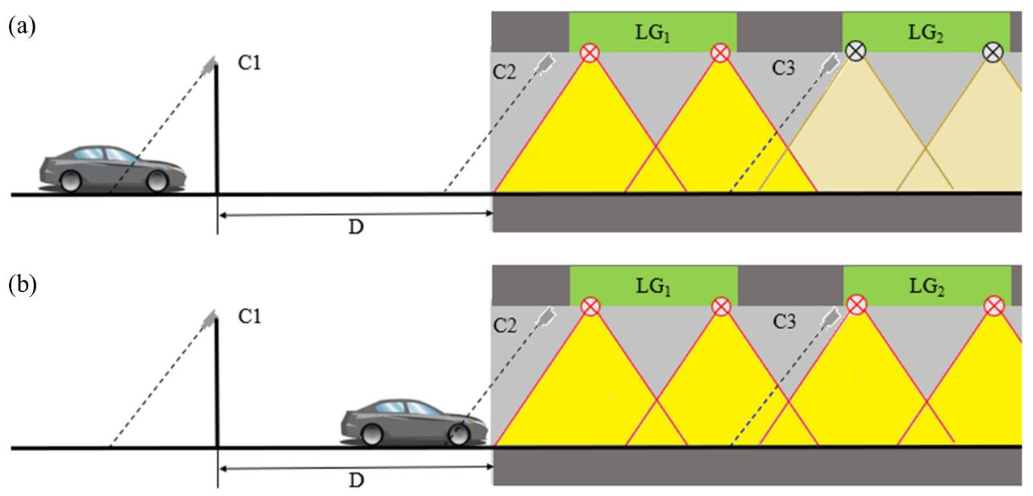
Figure 8 depicts the group control method for the tunnel entrance. When the surveillance camera C
1 detects the vehicle (
Figure 8a), the LED group LG
1 lights up with the power calculated by the dimming control system, and the other groups (LG
2, LG
3, …, LG
n) keep the minimum luminance, which is 10% of the maximum. When the vehicle enters the tunnel and is detected by C
2 (
Figure 8b), the LED group LG
2 lights up with the calculated power.
Figure 9 depicts the group control method for a vehicle driving through the interior of the tunnel. When the surveillance camera C
i detects the vehicle (
Figure 9a), the corresponding LED group LG
i adjusts to the luminance demand. Then, when the surveillance camera C
i+1 detects the vehicle, the corresponding LED group LG
i+1 adjusts its luminance to meet the luminance demand. At the same time, the LED group LG
i−1, which the vehicle has passed by, is adjusted to the minimum luminance to reduce energy consumption (
Figure 9b).
The flow chart of the intelligent control system is shown in
Figure 10. The LED group LG
i−1 is adjusted to darken only when there are no vehicles that are detected by the surveillance cameras C
i and C
i−1. To be more specific, if C
i detects a vehicle, LG
i adjusts to the calculated luminance, and the system records T
i (the time when C
i detects the vehicle). When C
i+1 detects the vehicle, the system judges whether C
i and C
i−1 detect the following vehicle, and if the answer is yes, LG
i−1 maintains the calculated luminance and refreshes T
i, otherwise, the system adjusts LG
i−1 to the minimum luminance. In other words, the intelligent control system can estimate whether there are following vehicles within the range of two LED groups, and if a following vehicle is detected by one of the surveillance cameras, C
i or C
i−1, the LED group LG
i−1 keeps a high luminance to fulfill the luminance demand for the following vehicle.
5. The Simulation Model
To evaluate the lighting effect of the intelligent lighting control system, a tunnel simulation model is established by DIALux lighting design software. The outside brightness is 3000 cd/m2 and the traffic flow is 1200 vel/h. The length and width are 3000 m and 8.4 m, respectively. The reflection coefficient of the sidewall is 0.75 and the pavement type is asphalt concrete.
In the simulation model, the lamps are GT78LED48/64/96/128W LED lamps which are produced by Thorn and the lamp installation height is 5.7 m.
Table 3 gives the suggested values and simulation values of the average illuminance of each lighting zone. The results show that the illumination of each lighting zone meets the requirements of the specification.
The length of the illumination segment (D = 400 m) is larger than the sum of the length of the threshold zone and the transition zone (L = 376 m). Thus, the illumination in the tunnel when a vehicle is detected by C
2 and C
3 is taken as an example to verify the lighting effect of the intelligent control system proposed in this paper. For a vehicle detected by C
2, the pseudo-color diagrams of illumination in the tunnel under the general lighting control system (all luminaires are adjusted to demand luminance) and the intelligent lighting control system proposed in this paper are shown in
Figure 11a,b, respectively. For a vehicle detected by C
3, the pseudo-color diagrams of illumination in the tunnel under the general lighting control system and the intelligent lighting control system proposed in this paper are shown in
Figure 11c,d, respectively. It can be seen that there is no obvious difference in the pseudo-color diagrams of illumination in the threshold zone and interior zone under the two different lighting control systems. The average illuminance curve in the tunnel when the vehicle is detected by C
2 and C
3, respectively, is shown in
Figure 12. The results show that the group control of luminaires can meet the illumination requirements of each illumination segment, and the part outside the driver’s visual range is reduced to 10% of the maximum power of the lamp to save energy.
6. Energy-Saving Effect
To evaluate the energy-saving effect of the intelligent control system, a calculation model of the LED group working time in a low brightness mode is established. Because the energy-saving effect of this intelligent control system is significant when the traffic flow is low, the traffic flow is assumed to be free flowing. Therefore, the headway obeys the negative exponential distribution, which can be expressed as:
where λ is the average arrival rate per unit time interval. The length of each illumination segment D is 400 m. Thus, the average duration of low illumination mode for each LED group when the unit vehicle passes through the tunnel with the headway exceeding
is calculated as follows:
Each LED group in low illumination mode can be calculated as follows:
According to the calculation model, the duration of each LED group in low illumination mode per hour under different velocities of the vehicle and traffic flow are evaluated. As shown in
Figure 13, the duration of low illumination mode for the LED groups decreases with the traffic flow. When
v = 40 km/h, the duration of low illumination mode for each LED group per hour for
q = 20 veh/h is 40.22 min; however, the duration of low illumination mode for each LED group per hour for
q = 400 veh/h is only 0.02 min. In addition, the velocity of the vehicle also significantly affects the energy-saving effect of the intelligent control system of tunnel lighting. Under the same traffic flow, the duration of low illumination mode for each LED group increases with the velocity of the vehicle. When
q = 20 veh/h, the duration of low illumination mode for each LED group for
v = 120 km/h is 52.5 min, which is 30.53% higher than that for
v = 40 km/h. Compared with the general lighting control system, the energy-saving effect is as high as 87.5% when
q = 20 veh/h and
v = 120 km/h.
7. Conclusions
In this paper, an intelligent control system of road tunnel lighting which can realize the effect of illumination moving with the vehicle is proposed. Compared with the general lighting control system, the finite visual field of the driver is considered in this paper, and the illumination outside the driver’s visual field is reduced by the group control of LED lamps.
In this system, Air Lamp lighting technology through the wide area fusion Internet of Things (WF-IoT) is used to achieve faster and more precise luminance control, and enable the group control of the luminaires. Besides, the control method of the intelligent control system is designed. By the group control of LED lamps, the tunnel lighting can be divided into several illumination segments. When the vehicle is detected by the surveillance cameras, the intelligent control system adjusts the corresponding LED group to the luminance demand according to the environmental conditions and traffic information. To ensure driving safety and comfort, the length of the illumination segment is calculated as 400 m. Two LED groups ahead of the vehicle maintain the luminance demand to ensure that a distance of 400~800 m in front of the driver is illuminated. The other LED groups maintain 10% of the maximum luminance to save energy. The simulation results show that the group control of luminaires can meet the illumination requirements of each illumination segment.
The energy-saving effect of the intelligent control system is evaluated by the calculation model. The results show that the duration of low illumination mode for the LED groups decreases with the traffic flow. When v = 40 km/h, the duration of low illumination mode for each LED group per hour is 40.22 min for q = 20 veh/h but only 0.02 min for q = 400 veh/h. In addition, the duration of low illumination mode for the LED groups increases with the velocity of the vehicle. When q = 20 veh/h, a maximum duration of low illumination mode for each LED group of 52.5 min for v = 120 km/h is obtained, which is 30.53% higher than that for v = 40 km/h. Compared with the general lighting control system, in which all luminaires are adjusted to the luminance demand, the energy-saving effect is as high as 87.5%. Therefore, the “illumination moving with the vehicle” intelligent control system of road tunnel lighting has an obvious energy-saving effect under the premise of ensuring driving safety.
Author Contributions
Conceptualization, Y.C. and Y.W.; methodology, Y.C.; software, R.R.; validation, R.R., F.C. and Y.W.; formal analysis, Y.C.; investigation, Y.C. and R.R.; writing—original draft preparation, Y.C. and R.R.; writing—review and editing, Y.W.; visualization, Y.C.; supervision, R.R. and Y.W. All authors have read and agreed to the published version of the manuscript.
Funding
This research was funded by the Research Program of the Department of Transport of Shaanxi Province (Grant No. 18-08K) and the National Key R&D Program of China (Grant No. 2017YFC0805306). This financial support is gratefully acknowledged.
Acknowledgments
The authors would like to thank the anonymous reviewers for their useful comments and the editor’s valuable suggestions for improving this manuscript.
Conflicts of Interest
The authors declare that there are no conflict of interest regarding the publication of this article.
References
- Ren, R.; Zhou, H.; Hu, Z.; He, S.; Wang, X. Statistical analysis of fire accidents in Chinese highway tunnels 2000–2016. Tunn. Undergr. Space Technol. 2019, 83, 452–460. [Google Scholar] [CrossRef]
- Lopez, J.C.; Peña-García, A. Determination of lighting and energy demands of road tunnels using vehicle based photographs of the portal gates: An accessible and safe tool for tunnel renewal and maintenance. Tunn. Undergr. Space Technol. 2018, 78, 8–15. [Google Scholar] [CrossRef]
- Zhao, L.; Qu, S.; Zhang, W.; Xiong, Z. An Energy-saving Fuzzy Control System for Highway Tunnel Lighting. Optik 2019, 180, 419–432. [Google Scholar] [CrossRef]
- Renzler, M.; Reithmaier, N.; Reinhardt, R.; Pohl, W.; Usmuller, T. A road tunnel model for the systematic study of lighting situations. Tunn. Undergr. Space Technol. 2018, 72, 114–119. [Google Scholar] [CrossRef]
- Moretti, L.; Cantisani, G.; Mascio, P.D. Management of road tunnels: Construction, maintenance and lighting costs. Tunn. Undergr. Space Technol. 2016, 51, 84–89. [Google Scholar] [CrossRef]
- Shuguang, L. An optimal model for tunnel lighting control systems. Tunn. Undergr. Space Technol. 2015, 49, 328–335. [Google Scholar] [CrossRef]
- Moretti, L.; Cantisani, G.; Mascio, P.D.; Caro, S. Technical and economic evaluation of lighting and pavement in Italian road tunnels. Tunn. Undergr. Space Technol. 2017, 65, 42–52. [Google Scholar] [CrossRef]
- Wencheng, C.; Zheng, H.; Liping, G.; Yandan, L.; Dahua, C. Performance of induction lamps and HPS lamps in road tunnel lighting. Tunn. Undergr. Space Technol. 2008, 23, 139–144. [Google Scholar] [CrossRef]
- Yu, N.; Ding, W. Application and Energy-saving Analysis of LED Light Source Used in the Tunnel Lighting. China Illum. Eng. J. 2016, 27, 46–51. [Google Scholar]
- Wang, Y.Q.; Xie, Y.L.; Lai, J.X. Experimental Research and Application of High Voltage Sodium Lamp and Low Emitting Diode Combined Lighting in Tunnel. Chin. J. Undergr. Space Eng. 2009, 5, 505–509. [Google Scholar]
- Carnì, D.L.; Grimaldi, D.; Lamonaca, F.; Martirano, L.; Parise, G. A smart control to operate the lighting system in the road tunnels. In Proceedings of the 2013 IEEE 7th International Conference on Intelligent Data Acquisition and Advanced Computing Systems (IDAACS), Berlin, Germany, 12–14 September 2013. [Google Scholar]
- Qin, L.; Dong, L.; Xu, W.; Zhang, L.; Yan, Q.; Chen, X. A “vehicle in, light brightens; vehicle out, light darkens” energy-saving control system of highway tunnel lighting. Tunn. Undergr. Space Technol. 2017, 66, 147–156. [Google Scholar] [CrossRef]
- Yu, T. Study on Energy-Saving Control in the Lighting System of Highway Tunnel; Xi’an University of Architecture and Technology: Xi’an, China, 2013. [Google Scholar]
- Dong, H. The Design of LED Intelligent tunnel Lighting Control System; South China University of Technology: Guangzhou, China, 2016. [Google Scholar]
- Wen, H.; Tian, Z. Application Research of WF-IoT Technology in Unattended Point. Internet Things Technol. 2018, 8, 39–41+47. [Google Scholar]
- Wen, H.; Sun, C. Evaluating the Economy of Air Lamp Smart Lighting Systems. Value Eng. 2018, 37, 51–54. [Google Scholar]
- Mashimo, H. State of the road tunnel safety technology in japan. Tunn. Undergr. Space Technol. 2002, 17, 145–152. [Google Scholar] [CrossRef]
- Zeng, H.; Qiu, J.; Shen, X.; Dai, G.; Liu, P.; Le, S. Fuzzy control of LED tunnel lighting and energy conservation. Tsinghua Sci. Technol. 2011, 16, 576–582. [Google Scholar] [CrossRef]
- I’Eclairage, C.I.d. Guide for the Lighting of Road Tunnels an Underpasses; Cie Publ.: Vienna, Austria, 2004; p. 88. [Google Scholar]
- JTG/T D70/2-01-2014. Guidelines for Design of Highway Tunnels; China Communications Press: Beijing, China, 2014. [Google Scholar]
- Fan, S.; Yang, C.; Wang, Z. Automatic Control System for Highway Tunnel Lighting. In Proceedings of the International Conference on Computer and Computing Technologies in Agriculture, Nanchang, China, 22–25 October 2010; pp. 116–123. [Google Scholar]
- JTJ 026.101999. Specifications for Design of Ventilation and Lighting of Highway Tunnel; China Communnications Press: Beijing, China, 2000; p. 39. [Google Scholar]
© 2020 by the authors. Licensee MDPI, Basel, Switzerland. This article is an open access article distributed under the terms and conditions of the Creative Commons Attribution (CC BY) license (http://creativecommons.org/licenses/by/4.0/).


