Article

A Sensorless Wind Speed and Rotor Position Control of PMSG in Wind Power Generation Systems

1
Department of Electrical Engineering, College of Engineering, Majmaah University, Almajmaah 11952, Saudi Arabia
2
Department of Electrical Engineering, College of Engineering, Assuit University, Assuit 71515, Egypt
3
Saudi Electricity Company Chair in Power System Reliability and Security, King Saud University, Riyadh 11421, Saudi Arabia
4
Sustainable Energy Technologies Center, King Saud University, Riyadh 11421, Saudi Arabia
5
Electrical Engineering Department, Mansoura University, Mansoura 35516, Egypt
6
Institute of Research and Development, Duy Tan University, Da Nang 550000, Vietnam
7
Faculty of Civil Engineering, Duy Tan University, Da Nang 550000, Vietnam
*
Author to whom correspondence should be addressed.
Sustainability 2020, 12(20), 8481; https://doi.org/10.3390/su12208481
Submission received: 9 September 2020 / Revised: 3 October 2020 / Accepted: 5 October 2020 / Published: 14 October 2020

Abstract

:
Currently, among the topologies of wind energy conversion systems, those based on full power converters are growing. The permanent magnet synchronous generator (PMSG) uses full power converter to allow wide speed ranges to extract the maximum power from the wind. In order to obtain efficient vector control in a synchronous generator with permanent magnets, it is necessary to know the position of the rotor. The PMSGs work over a wide range of speed, and it is mandatory to measure or estimate their speed and position. Usually, the position of the rotor is obtained through Resolver or Encoder. However, the presence of these sensor elements increases the cost, in addition to reducing the system’s reliability. Moreover, in high wind power turbine, the measured wind speed by the anemometer is taken at the level of the blades which makes the measurement of the wind speed at a single point inaccurate. This paper is a study on the sensorless control that removes the rotor position, speed sensors and anemometer from the speed control. The estimation of the rotor position is based on the output of a rotor current controller and the wind speed estimator is based on the opposition-based learning (OBL), particle swarm optimization and support vector regression.

1. Introduction

In the current global situation, promoting sustainability is no longer a challenge and has become a necessity for the socio-environmental balance of the planet. In the last few decades, unprecedented changes have been noticed in the consumption of energy resources and in the generation of energy. These can be highlighted, as the main causes, the growth of the renewable energy market coupled with the increase in installed capacity, the growth in the use of new resources and the improvements and evolutions of technologies. In 2005, the main source of energy consumed in the world was oil and represented approximately 35.96% of the primary matrix. In 2018, that number dropped to 33.1%. Although oil is the main source used worldwide, there is an increase in the participation of other sources. Wind energy stands out, which went from a simple 0.22% to 9% of world generation in the same period [1].
Wind power generation is a technology that has secured market competitiveness and technological power among various renewable energy sources, and the economy is close to thermal power generation. In the past, many constant-speed wind turbines using squirrel cage induction generators have been used, but in recent years, a permanent magnet synchronous generator (PMSG) driven by vector control with a back-to-back PWM converter between the generator and the grid has proven to be superior in variable-speed driving. PMSG is rapidly increasing in use because of its high wind speed utilization, high efficiency, low maintenance cost, and relatively simple control compared to wind power generation systems using Doubly Fed Induction Generator (DFIG) [2]. Variable speed wind turbine generator using PMSG is being actively researched due to various advantages such as high efficiency, low maintenance cost and wide operating range.
In medium and low power applications, it is preferred to use techniques without sensors, with the objective of reducing implementation and maintenance costs, allowing the vector control of the machine from an estimate of position and speed [3]. The most used methods of sensorless control for PMSG, which aims to detect position in a wide range of speed, are: injection of high frequency signal, Phase Locked Loop (PLL), Extended Kalman filter and Sliding Mode Observer (SMO) [4,5,6,7].
The amount of wind energy produced varies with the change in wind speed. The maximum power extracted depends not only on the wind speed, but also on the accuracy of the WECS (Wind Energy Conversion and Storage) operating point. Thus, in order to maximize the energy extracted, it is necessary to use Maximum Power Point Tracking (MPPT) algorithms [8]. The MPPT methods developed vary in the technique used, in the complexity, in the number of used sensors, in the memory requirement, and in the efficiency range, among others [9]. However, all of them have as their main objective to optimize the rotation speed of the generator in relation to the wind speed [10]. Variable speed wind turbines are designed for this purpose and are generally characterized as having greater efficiency than fixed speed wind turbines [11]. Thus, using MPPT algorithms, the rotation speed of the generator can be controlled in order to extract as much energy as possible.
The MPPT algorithms that currently exist can be divided into three main types, namely the Perturb and Observe (P&O) control (also known as Hill Climbing Searching control), the Power Signal Feedback (PSF) control and the Tip-Speed ratio control method (TSR).
The PSF control requires prior knowledge of the wind turbine parameters, more precisely, the curve that relates the output power to the speed of rotation of the turbine. This is obtained through practical tests, with the aid of a wind tunnel, applied to the system under study, as the curve is specific to each system [12]. The speed of rotation of the wind turbine is monitored to select the appropriate power curve and determine which optimum power to impose on the system. Then, the current power is compared to the optimum power and, according to the error obtained, the controller will act in order to approximate the current power to the optimum.
The main advantages of this method are its simplicity and fast response. However, on the other hand, it has several disadvantages, both in terms of costs and in terms of precision. The main barrier in the widespread application of this technique is obtaining the maximum power curve, as this, in addition to varying from one system to another, also varies significantly with the use of the system and with variations in weather conditions, causing the performance of the system to change. Tests for determining the maximum turbine power curve also constitute a major investment, especially when their results are only temporary.
The TSR control method, as the name implies, requires prior knowledge of the TSR values. This method regulates the speed of rotation of the generator, in order to maintain the optimum value of the TSR, for which the extracted power is maximum [13,14]. The working principle of this method is similar to the one mentioned above, with the only differences being the need to calculate the rotation speed of the generator by measuring wind speed and knowledge of the optimal TSR. The optimal value of the TSR can be determined experimentally or theoretically and is stored as a reference.
The P&O control technique is considered to be the simplest and most used due to its reliability [10]. The P&O method is a mathematical optimization technique used to search for the maximum local points of a given function. This method is based on disturbing a control parameter with a small step and observing the resulting changes in the target function. This disturbance and observation sequence is carried out until the difference between the value of two consecutive sequences is zero. If the operating point is on the left side of the maximum power point (MPP), the control algorithm must move the operating point to the right side, so that it is closer to the MPP and, vice versa, if the operating point is on the right side of the MPP [15].
The adaptive control methods, such as neural network, are also used, which usually estimate some parameters, in association with other MPPT search methods. The artificial neural networks are made up of artificial neurons that are programmed to simulate the functioning of the human neuron. They are usually composed of three layers: input, hidden layer and output layer, however, there are cases of two or a single layer composing the network. The hidden layers can contain a diverse number of neurons interconnected by synoptic weights, which are responsible for the degree of network performance [16]. The network training process consists of adjusting the synaptic weights to such an extent that the network acquires the ability to generalize its actions, thus being able to make decisions, separate standards, etc. The input variables for a neural network used in MPPT control of wind systems can be: wind speed, rotor speed, and terminal voltage. The output variable is normally used as a reference signal, such as wind speed, rotor speed, and switching cycle for the converter [17].
Support Vector Regression (SVR) algorithm has been used in several studies to estimate the wind speed from the power speed characteristics. SVR method has more advantages over Artificial Neural Network (ANN) which may be stuck in one of a local minima, while the solution to SVR is global and unique [16,17,18,19,20]. However, the performance of SVR algorithm, when its parameters are fixed, deteriorated when the wind speed varies continuously and over a wide range. Therefore, optimized SVR parameters improve the wind speed estimation over a wide range with high accuracy.
Updating and optimizing the SVR parameters can be achieved by adding an optimization technique such as Genetic algorithm (GA) and Particle Swarm Optimization (PSO). The latter algorithm shows high-optimization capability, fast convergence, and simplicity over the other optimization techniques. By using the PSO algorithm to tune the SVR parameters, the PSO population is generated randomly which produces inaccurate results when it is used alone to optimize the SVR parameters. As a result, the opposition-based learning (OBL) method can be used to solve the inaccuracy and randomness of the PSO. Modifying the population of PSO using OBL, namely OPSO, can optimize the SVR parameters at different conditions and obtain knowledge about the corresponding global optimum parameters.
If the PMSG is to be controlled without a position sensor, the generator rotor angle and speed control necessary information for torque control should be estimated from equations based on the basic model of the generator. At this time, as equations for the basic model of the electric generator, the voltage equation related to the electric system and the mechanical equation related to the mechanical system are mainly used. In conventional sensorless techniques, the focus is on the more accurate estimation of magnetic flux in obtaining information from voltage equations. As a technique of estimating speed and integrating it again to obtain information about the rotor angle, a method using a state estimator is most common [21].
So far, several extensive researches have been applied to improve the rotor position sensorless control. The main approaches can be categorized into three major types:
(1)
Magnetic flux detection technique by integration of voltage;
(2)
Techniques using state estimators;
(3)
Control method using Kalman filter.
In this study, a PMSG wind power conversion system based on a sensorless control is proposed. The PMSG rotor position and the rotational speed are estimated based on the feedback voltage using output of the generator q-axis current controller. The estimation of the wind speed is achieved by using the Opposition Particle Swarm Optimization-Support Vector Regression (OPSO-SVR)algorithm that is based on the sampling data of generator power, speed and SVR parameters. The SVR parameters are calculated from the training process and optimized by the OPSO. The parameters that are obtained from OPSO-SVR are used in the next step until the estimation process is done. The novelty of the proposed sensorless control lies with the fact that the PMSG drive is using estimated wind speed and estimated rotational speed in tracking the MPPT instead of the traditional speed measurement. Estimation of wind speed and rotational speed reduce the system cost especially in small systems. Experimental results show good current control results in the starting acceleration section, and good sensorless speed control performance can be verified at very low rotating speed.
The rest of the paper is organized as follows. In Section 2, the modeling of the wind turbine, PMSG, the rotor speed estimation algorithm, the control of the machine side converter and grid side converter are presented. Then, the estimation of the wind speed by using SVR-PSO is discussed in Section 3. Lastly, the experimental results are presented in Section 4 to validate the performance of the proposed algorithm.

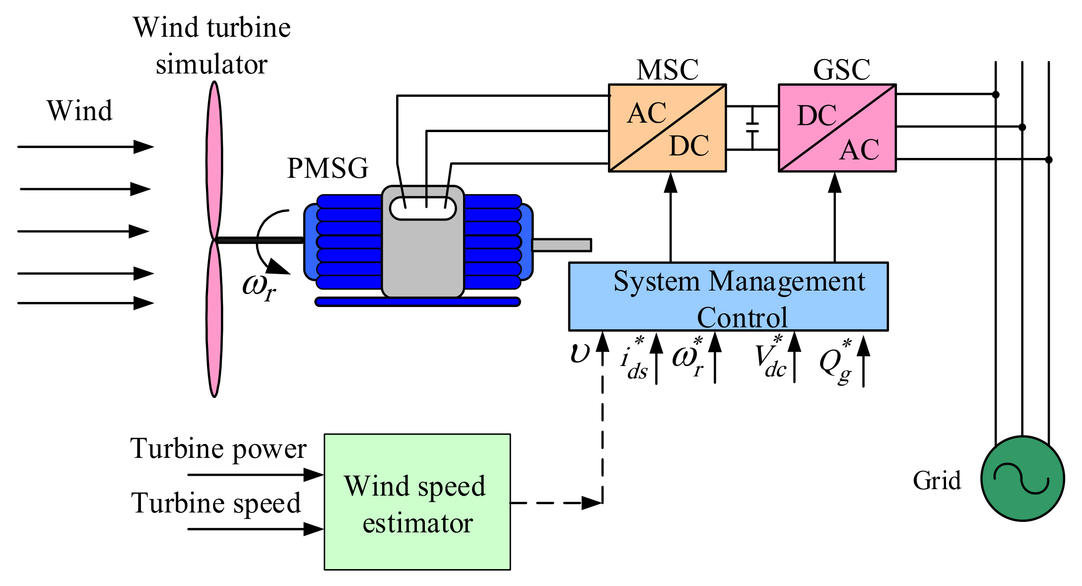
2. System Description

The overall structure of the wind turbine system consists of a wind turbine simulator, PMSG, a back-to-back converter, and the system controller as shown in Figure 1. The PMSG stator is connected to the Machine Side Converter (MSC) while the grid is connected to the Grid Side Converter (GSC). The MSC can control the active power by controlling the generator speed to the value ω r * which allow the generator to extract the maximum power from the wind. The generator flux level is adjusted to optimize the generator loss by the generator d-axis current i d s * . The GSC regulates the DC-link voltage to the reference value V d c * and the reactive power Q g * supplied to the grid. The generator modeling and control is discussed in the following sections.

2.1. Wind Turbine Modeling

The aerodynamic model of the wind turbine used in this work is proposed by [22]. The mechanical torque available in the turbine is given as follows:
T m   =   1 2 ρ π R 3 υ 2 C p β , λ / λ
Where ρ is air density, R is blade radius, υ   is wind speed, Cp is power coefficient, β is pitch angle, and λ is the Tip speed ratio. The relationship between λ and Cp according to pitch angle β is shown in Figure 2.
The mechanical power captured by wind turbines from the wind is expressed as
P m   =   T m ω r
where ω r is the rotor electrical angular speed.
The dynamics of the wind turbine’s rotational speed ω r are modeled by the mechanical torque T m , the electromagnetic torque T e , the viscous friction coefficient Bm, and the equivalent inertia Jeq combined with the wind turbine and generator’s inertia as follows [23]:
d ω r d t   =   T m     T e     B m ω r / J e q

2.2. PMSG Modeling and Control

In a rotating d-q reference frame, the stator voltage and current vectors can be expressed in the synchronous reference frame as follows [24,25,26,27,28]:
v d s r v q s r   =   R s   +   p L s ω r L s ω r L s R s   +   p L s i d s r i q s r   +   e d s r e q s r
where v d s r and v q s r are the stator d-q synchronous reference frame voltages, and i d s r and i q s r are the stator d-q synchronous reference frame currents. Rs is the stator winding resistance, ω r is the rotor electrical angular speed, L s   is the equivalent stator inductance, and p is the differential operator d/dt.
The electromotive force is given by Equation (5):
e d s r e q s r   =   0 ω r Ψ f
where Ψ f is the magnitude of the magnetic flux linking the stator windings.
Finally, the synchronous coordinate system d-q voltage equation of PMSG can be obtained:
v d s r v q s r   =   R s   +   p L s ω r L s ω r L s R s   +   p L s i d s r i q s r   +   0 ω r Ψ f
Since the rotor of the PMSG has no input and output of energy, it can be regarded as electromagnetic torque, which can be expressed as shown in Equation (7):
T e   =   3 2 n p Ψ f i q s r
where n p is the number of poles.
The active power and reactive power can be defined as follows:
P e   =   T e ω r   =   3 2 v d s r i d s r   +   v q s r i q s r
Q e   =   3 2 v d s r i d s r     v q s r i q s r
Through the Equations (8) and (9), the active and reactive power outputs of the PMSG can be controlled by the q-axis and d-axis currents. Figure 3 shows the complete diagram of the control system used for the machine side converter (MSC).
The wind speed estimation algorithm uses the wind turbine characteristics to predict the wind speed. For each wind speed, there is only rotor speed and generator power in any fixed pitch angle. By measuring these quantities, the estimator uses these values as training data and all these samples are collected offline and then used online. The rotor position detector uses the d-axis current controller output to detect the rotor speed and position.
The generator speed controller basically generates a current command so that the actual generator speed follows the speed reference. Therefore, the speed controller can fulfill its function only when the basic assumption is that the torque coinciding with the current command is accurately output from the generator is established. This current command is input to the current controller and used as the reference current of the current controller. At this time, the current controller operates fast enough so that the same current as the reference value is applied to the generator. The information of rotor position error can be extracted from the d-axis current controller output voltage, V d s _ f b , as Equation (10) [29]:
θ ^ e r r   =   V d s _ f b e ω ^ r Ψ f
where θ ^ e r r     is   the   position error, and ω ^ r indicates the estimated rotor speed. The position error in Equation (10) can be controlled to zero by rotor position tracking PI controller as shown in Figure 3.
The error of the rotor position is the difference between the real position and the estimated value.
Equation (10) is used as the input of the PI controller, where the output of the controller is the estimated rotor angular velocity ω ^ r , and the output of the integrator is rotor position θ ^ .

2.3. Grid-Side Control

The grid-side converter is responsible for stabilizing the voltage level of the DC bus and the reactive power injected into the electrical network through cascade controllers. The compensation of the DC bus and reactive power is carried out by external control loops that provide the references for internal current loops.
The goal of PMSG’s GSC control is to control the DC-link voltage of the back-to-back converter and to control the reactive power output to the grid. The grid active power and reactive power output can be defined by the d-q reference frame rotating synchronously with the grid voltage as follows [30]:
P g r i d   =   3 2 v d g e i d g e   +   v q g e i q g e
Q g r i d   =   3 2 v d g e i d g e   +   v q g e i q g e
From Equations (11) to (12), GSC shows that the active and reactive power outputs are determined by d- and q-axis current control. Accordingly, DC-link voltage control is possible through q-axis current control, and reactive power output to the system can be controlled through d-axis current control.
The GSC voltage equations redefined to d-q reference frame for grid voltage can be expressed as follows:
V d g e V q g e   =   R g   +   p L g ω e L g ω e L g R g   +   p L g i d g i q g   +   V d g V q g
where Rg, Lg is the impedance between the GSC and the grid, ω e is the grid angular frequency, and V d g , V q g and i d g , i q g are the d-axis and q-axis components of the GSC voltage and current, respectively. v d g e and v q g e are the d-axis and q-axis grid voltage, respectively.
The grid-side converter is responsible for controlling the voltage level of the DC-link and the reactive power injected into the grid through cascade controllers. Figure 4 presents the control block diagram for the grid-side converter. In this structure, the error between the reference DC-link voltage and the measured voltage passes through a PI controller to generate a d-axis reference current. The reference q-axis current is defined as a function of the reactive flow necessary to control the power factor of the grid current, therefore, the external loop is the reactive power control loop and its output is the reactive power error which is passed to the PI controller. The output of the PI controller is the reference value of the q-axis current.

3. Wind Speed Estimation

In this section, the implementation of SVR and PSO algorithms in estimating the wind speed are presented and discussed.

3.1. Support Vector Regression

Support Vector Machines (SVMs) are machine learning techniques derived from two solid foundations: Theory of Statistical Learning and Mathematical Optimization. SVMs have recently been successfully applied to a variety of problems ranging from character recognition to object recognition based on appearance [31]. Some of the reasons for this success are related to the fact that this technique exhibits good generalization performance in many real databases, it is theoretically well- founded, the training process eliminates the possibility of local minimums, there are few free parameters to adjust, and the architecture does not need to be found by experimentation [32]. SVMs are a learning method able to analyze the input data and find certain patterns by minimizing the structural risk and mapping patterns into higher-dimensional feature spaces to provide optimum identification [33]. The results of applying this technique are comparable and often superior to those obtained by other learning algorithms, such as ANN. Therefore, SVMs are widely used in n data classification and regression analysis due to its superiority over most other supervised learning methods.
Support Vector Regression (SVR) is a non-linear regression technique based on Support Vector Machines. This technique is often used in the areas of pattern recognition and text classification. Instead of minimizing the observed training error, SVR tries to minimize the error boundary, in order to obtain a generalized performance.
The SVR concept is based on the computational calculation of a linear regression function in a space with a high dimensional characteristic, where the input data is mapped through a non-linear function. SVR has been applied in several areas, such as: time series predictions, approximation of highly complex engineering analysis, and choice of loss functions, etc. [34].
The operation of the SVR algorithm is based on the supervised learning methodology. This methodology makes a system learn a function, from a sample of training data (x1, y1), (x2, y2), ….., (xn, yn), where x is the input space and y the output space. In this context, the objective of the SVR is to find a function f (x) that presents, at most, one deviation ε in relation to the target values yi. In other words, we are looking for a function with an error margin characterized by the interval [yi+, yi−ε].
Assuming functions in the form [35]:
f x   =   < w x >   +   b
Where w   R n and b   R  , b is the bias and w represents the weight vector which corresponds to minimizing the measure || w || 2 . In this way, the original SVR optimization problem is modeled with:
Minimizing   1 2 || w || 2
subject to:
y i     < < w x i > >     b     ε < < w x i > >   +   b       y i     ε i   =   1 , 2 , ............. , n
It is not always possible to guarantee the viability of the problem described above, because there are points that violate its restrictions. For this reason, a loss function ε is studied, which introduces non-negative slack variables ξ i ,   ξ i * whose purpose is to penalize data that fall outside the f x i y i ε margin [36]. The problem formulation is then [36]:
R r e g f =   1 2 || w || 2   +   C ξ i * i = 1 n ( ξ i   +   )
subject to:
y i     < w x i >     b     ε   +   ξ i * < w x i >   +   b       y i     ε   +   ξ i i   =   1 , 2 , ............. , n   ξ i , ξ i *     0
where C is a constant regularization determining the trade-off between minimizing training errors and minimizing the model complexity term || w || 2 . It is known that the generalization performance of an SVR model depends on a good adjustment of the regularization parameter C and the ε parameter of the loss function.
Thus, the linear function f x   of rewrite is as follows [37]:
f x =   i   =   1 n α i     α i * . x i , x + b
The non-negative Lagrange multipliers ( α i α i * ) are introduced to transform the optimization problem in Equation (13) to dual problems. The dual formulation of the SVR problem provides an alternative to modeling in a high dimensional space. Additionally, it is possible to perform a non-linear mapping of temporal input data to higher spaces, in which linear regression becomes possible, provided that SVR approaches based on non-linear kernel functions are used, which are denoted, generically, by K x i , x [38].
Consequently, the SVR approximation function consists of a non-linear model and is reissued as follows:
f x = i = 1 n α i α i * . K x i , x + b
In this paper, the used kernel function is Radial Base Function (RBF):
K x i , x   =   e x p x i , x σ 2

3.2. The O-Particle Swarm Optimization

The PSO optimization method was originally developed by Kennedy and Eberhart [39]. The PSO technique is inspired by the flight of birds, which are called particles. This method starts up randomly, through a set of particles with random speeds and positions. After this initialization, individuals are evaluated using the evaluation function. In a PSO algorithm, there is a set of vectors whose trajectories oscillate around a region defined by each best individual position (PBest) and the best position of the others (GBest).
The position of the particle, x i , is updated according to the Equation (19) [40,41]:
x i t   +   1 =   x i t +   w v i t   + C 1 r n d P B e s t     x i t +   C 2 r n d G B e s t     x i t
In Equation (19), v i t represents the velocity vector of particle i at time t, w is the inertia factor, rnd represents random numbers of uniform distribution between [0,1], C1 and C2 respectively represent the social and cognitive parameters, PBest is the best individual position and GBest is the best social position. Parameters C1 and C2 adjust the balance between social influence and individual particle learning. C1 and C2 are set as [42]:
x = 2 φ 1 + φ 2 4 φ
C 1   =   x φ 1 , C 2   =   x φ 2
where φ   = φ 1   +   φ 2   >   4 . In this paper, φ 1   =   φ 2   =   2.08 ; thus, C 1   =   C 2   =   1.6 .
The OBL-based population initialization algorithm is used to replace the random initialization feature of PSO and the flowchart of OBL initialization is shown in the flowchart in Figure 5 [43,44,45]. The collected training samples are collected from the turbine power-speed characteristics for each wind speed. For each sample, the rotation speed and the corresponding turbine power ( ω i , p i , j | i   =   1 , .... , 70 , j   =   1 , ..... , 70 ) are combined as a pair for the inputs of SVR estimator as shown in Figure 6.

4. Experimental Results

Figure 7 shows the complete control system built for the experiment to control the permanent magnet synchronous generator. Basic configuration consists of 2.7 kW PMSG, 3 kW induction motor used as wind simulator, inverter to supply electric power, and controller. The switching frequency of the PWM inverter was 10 kHz, and the processor used TMS320VC33-120 MHz. The specifications of the PMSG and the cage inductors are shown in Table A1 and Table A2 in the Appendix A.
The validity of the wind speed estimator is tested first as shown in Figure 8a. The wind speed varies continuously to simulate the stochastic nature of wind speed in the range between 5.5 and 8.5 m/s with a series of high frequency harmonics. In this figure, the mean wind speed is 8 m/s and oscillates from 5.5 to 8.5 m/s as shown in Figure 8a. It is noticeable that the difference between the estimated wind speed and the measured one has very slight delay due to the execution time. The speed estimation error is shown in Figure 8b and it is seen that the speed error is always less than 0.25 m/s. Figure 8c shows the output power corresponding to the maximum at the given wind speed. The maximum power point is always maintained due to the accuracy of the estimation method and the fast response of the controller.
Figure 9 shows the estimated speed, measured speed and rotor position when the speed command of 400 rpm is given in steps. From above, the estimated speed and measured speed show good speed response characteristics and estimated characteristics in the transient and steady state with respect to the step speed command. The problem of the rotor speed estimation methods is the low speed region which is overcome in these results. Even though the estimation accuracy is higher in high rotor speed, the estimation error is still acceptable.
Figure 10 shows the estimated speed and actual speed, estimated rotor position and actual rotor position for the speed command of 400 rpm. In the figure, it can be seen that in the transient state at the initial low speed, the dynamic characteristics are lowered because the bandwidth of the rotor position estimation PI controller is low. In the same principle, the estimated rotor position is also initially slow due to low bandwidth, but after a certain speed, the estimated bandwidth is also improved.
Figure 8, Figure 9, Figure 10 compare the measured and estimated wind and rotor speed of the PMSG at different wind speed conditions and rotor speed values, and these results show that the algorithms accurately estimate the wind and rotor speed, which are then used for real-time MPPT and control of PMSG.
Figure 11 shows rotor position estimation characteristics at steady state for the speed command of 400 rpm. As can be seen from the figure, the rotor position error in the low speed region of 400 rpm is almost zero, which shows high position estimation characteristics.
Figure 12 shows the estimated and measured rotor speed when the speed command is changed to 500-600-500 rpm. As can be seen from the figure, even when the speed command is changed to 500-600-500 rpm in steps, it shows stable response characteristics and estimated characteristics. It is also noticeable that the response of the estimator in high rotor speed is high and the error is almost zero.
Figure 13 shows the performance of the speed controller at 800 rpm speed command. It is noticed that the speed is maintained at 800 rpm and the q-axis current is well controlled with low harmonic content.
Figure 12 and Figure 13 show a comparison between the estimated rotor speed and the reference value in case of step change of the speed reference and in steady state condition. In both cases, the proposed algorithm correctly estimates the optimal rotor speed which is then used for maximum power generation during various conditions.

5. Discussions and Conclusions

In this work, the modeling and control of an experimental wind generation system with PMSG and a bidirectional full converter (Back-to-Back) connected to the grid was carried out. The work sought to contribute to a better implementation of sensorless control of PMSG by estimating the rotor speed, position, and wind speed, as well as understanding of the functioning of the system in general and of the control techniques used. The mathematical models of the wind generation system, the design of the estimators and controllers for the prototype were presented, as well as the results obtained through the experimental setup. A new sensorless method that can be applied to high and low speed operation of PMSG which is based on the output of the current controller in the speed control loop was applied. The wind speed estimation scheme for wind-driven PMSG was proposed. The OPSO-SVR algorithm that estimates the wind speed value based on the training data from previous offline training was presented. The proposed method is implemented to overcome the SVR parameter selection in a wide speed range. By using OPSO, the optimum SVR parameter optimization can be obtained faster and more accurately. The main advantages of the proposed algorithm are the fast and accurate estimating of the wind speed, even due to the fast optimization and tuning of the SVR parameters which featured an excellent tracing for the real value and the independency of the generator turbine constants or torque measurements. Experimental results presented show the excellent performance achieved whether for estimating the wind speed or the rotational rotor speed.
In the future, the rotor speed estimation can be applied in two modes which are very low speed and high speed. Different SVR parameters can be obtained for both modes to guarantee accurate estimation at different speed levels.

Author Contributions

Conceptualization, A.G.A.-K.; methodology, A.G.A.-K.; validation, A.G.A.-K.; formal analysis, A.M.E.; investigation, A.M.E.; data curation, A.S.A.; formal analysis, I.T.; writing—Original draft preparation, P.R.P.; writing—Review and editing, P.R.P.; funding acquisition, A.S.A. All authors have read and agreed to the published version of the manuscript.

Funding

The authors would like to thank Deanship of Scientific Research at Majmaah University for supporting this work under project number RG. 2019-19.

Conflicts of Interest

The authors declare no conflict of interest.

Appendix A

Table A1. Parameters of the 3 kW squirrel cage induction generator.
ParametersValue
Stator resistance0.93 Ω
Rotor resistance0.533 Ω
Iron loss resistance190 Ω
Stator leakage inductance0.003 H
Rotor leakage inductance0.003 H
Mutual inductance0.076 H
Table A2. Parameters of the Permanent Magnet Synchronous Machine.
ParametersValue
Rated power2.7 kW
Rated speed1200 rpm
Number of poles6
Rated current9.5 A
Stator resistance0.5 Ω
Stator inductance5.5 mH

References

  1. Salah, M.M.; Abo-Khalil, A.G.; Praveen, R. Wind speed characteristics and energy potential for selected sites in Saudi Arabia. J. King Saud. Univ. Eng. Sci. 2019. [Google Scholar] [CrossRef]
  2. Morimoto, S.; Nakayama, H.; Sanada, M.; Takeda, Y. Sensorless output maximization control for variable-speed wind generation system using IPMSG. IEEE Trans. Ind. Appl. 2005, 41, 60–67. [Google Scholar] [CrossRef]
  3. Gonzalez, L.G.; Figueres, E.; Garcera, G.; Carranza, O.; Gonzalez-Espin, F. Synchronization techniques comparison for sensorless control applied to pmsg. In Proceedings of the International Conference on Renewable Energies and Power Quality (ICREPQ 09), Barcelona, Spain, 8–10 September 2009; pp. 978–980. [Google Scholar]
  4. Jiang, D.; Zhao, Z.; Wang, F. A sliding mode observer for pmsm speed and rotor position considering saliency. In Proceedings of the Power Electronics Specialists Conference, PESC 2008, Rhodes, Greece, 15–19 June 2008; pp. 809–814. [Google Scholar]
  5. Xiang, X.; He, Y. Sensorless vector control operation of a pmsm by rotating high-frequency voltage injection approach. In Proceedings of the International Conference on Electrical Machines and Systems (ICEMS), Seoul, South Korea, 8–11 October 2007; pp. 752–756. [Google Scholar]
  6. Fan, S. A new sensorless control strategy used in direct-drive pmsg wind power system. In Proceedings of the IEEE International Symposium on Power Electronics for Distributed Generation Systems (PEDG), Hefei, China, 16–18 June 2010; pp. 611–615. [Google Scholar]
  7. Yang, S.; Zhang, X.; Zhang, C.; Xie, Z.; Li, F. Sensorless control for pmsg in direct-drive wind turbines. In Proceedings of the IEEE International Symposium on Power Electronics for Distributed Generation Systems (PEDG), Hefei, China, 16–18 June 2010; pp. 81–84. [Google Scholar]
  8. Eltamaly, A.M.; Alolah, A.I.; Abdel-Rahman, M.H. Improved simulation strategy for DFIG in wind energy applications. Int. Rev. Model. Simul. 2011, 4, 525–532. [Google Scholar]
  9. Abo-Khalil, A.G.; Lee, D.C. Optimal Efficiency Control of Wind Generation System Using Fuzzy Logic Control. In Proceedings of the KIEE Conference; The Korean Institute of Electrical Engineers: Seoul, Korea, 2005. [Google Scholar]
  10. Senjyu, T.; Tamaki, S.; Urasaki, N.; Uezato, K.; Higa, H.; Funabashi, T.; Fujita, H.; Sekine, H. Wind velocity and rotor position sensorless maximum power point tracking control for wind generation system. Renew. Energy 2006, 31, 1764–1775. [Google Scholar] [CrossRef]
  11. Zhi, D.; Xu, L.; Williams, B.W. Model-based predictive direct power control of doubly-fed induction generators. Ieee Trans. Power Electron. 2009, 25, 341–351. [Google Scholar]
  12. Chien-Hung, L.; Yuan-Yih, H. Effect of rotor excitation voltage on steady-state stability and maximum output power of a doubly-fed induction generator. IEEE Trans. Ind. Electron. 2010, 58, 1096–1109. [Google Scholar]
  13. Rahimi, M.; Parniani, M. Transient Performance Improvement of Wind Turbines With Doubly Fed Induction Generators Using Nonlinear Control Strategy. IEEE Trans. Energy Convers. 2009, 25, 514–525. [Google Scholar] [CrossRef]
  14. Ali, M.E. Modeling of wind turbine driving permanent magnet generator with maximum power point tracking system. J. King Saud Univ.-Eng. Sci. 2007, 19, 223–236. [Google Scholar]
  15. El-Sousy, F.F.M.; Orabi, M.; Godah, H. Maximum power point tracking control scheme for grid connected variable speed wind driven self-excited induction generator. KIPE J. Power Electron. 2006, 6, 45–51. [Google Scholar]
  16. Abokhalil, A.G. Grid Connection Control of DFIG for Variable Speed Wind Turbines under Turbulent Conditions. Int. J. Renew. Energy Res. 2019, 9, 1260–1271. [Google Scholar]
  17. Abo-Khalil, A.G.; Ab-Zied, H. Sensorless Control for DFIG Wind Turbines Based on Support Vector Regression. In Proceedings of the Industrial Electronics Conference IECON, Montreal, QC, Canada, 25–28 October 2012. [Google Scholar]
  18. Abo-Khalil, A.G.; Lee, D.C.; Seok, J.K. Variable Speed Wind Power Generation System Based on Fuzzy Logic Control for Maximum Output Power Tracking. In Proceedings of the 2004 IEEE 35th Annual Power Electronics Specialists Conference (IEEE Cat. No.04CH37551), Aachen, Germany, 20–25 June 2004; pp. 2039–2043. [Google Scholar]
  19. Ab-Khalil, A.G. Control system of DFIG for Wind Power Generation Systems; LAP LAMBERT Academic Publishing: Raja, Latvia, 2015; ISBN-10: 3659649813, ISBN-13: 978-3659649813. [Google Scholar]
  20. Abo-Khalil, A.G.; Kim, H.G.; Lee, D.C.; Seok, J.K. Maximum Output Power Control of Wind Generation System Considering Loss Minimization of Machines. In Proceedings of the 30th Annual Conference of IEEE Industrial Electronics Society, 2004 (IECON 2004), Busan, South Korea, 2–6 November 2004; pp. 1676–1681. [Google Scholar]
  21. Ma, Z.; Zhang, X. FPGA Implementation of Sensorless Sliding Mode Observer with a Novel Rotation Direction Detection for PMSM Drives. IEEE Access 2018, 6, 55528–55536. [Google Scholar] [CrossRef]
  22. Flieh, H.; Slininger, T.; Lorenz, R.D.; Totoki, E. Self-Sensing via Flux Injection with Servo Dynamics including a Smooth Transition to Back-EMF Tracking. In Proceedings of the 2018 IEEE Energy Conversion Congress and Exposition (ECCE), Portland, OR, USA, 23–27 September 2018; pp. 1762–1769. [Google Scholar]
  23. Park, J.; Sandberg, I.W. Universal Approximation Using Radial-Basis-Function Networks. Neural Comput. 1991, 3, 246–257. [Google Scholar] [CrossRef] [PubMed]
  24. Xu, D.; Wang, B.; Zhang, G.; Wang, G.; Yu, Y. A review of sensorless control methods for AC motor drives. China Electrotech. Soc. Trans. Electr. Mach. Syst. 2018, 2, 104–115. [Google Scholar] [CrossRef]
  25. Abokhalil, A.G.; Alyami, S.; Sayed, K.; Alhejji, A. Dynamic Modeling of Wind Turbines Based on Estimated Wind Speed under Turbulent Conditions. Energies 2019, 12, 1907. [Google Scholar] [CrossRef] [Green Version]
  26. Abo-Khalil, A.G.; Alghamdi, A.; Tlili, I.; Eltamaly, A. A Current Controller Design for DFIG-based Wind Turbines Using State Feedback Control. IET Renew. Power Gener. 2019, 13, 1938–1949. [Google Scholar] [CrossRef]
  27. Strachan, B.P.W.; Jovcic, D. Dynamic Modelling, Simulation and Analysis of an Offshore Variable-Speed Directly-Driven Permanent-Magnet Wind Energy Conversion and Storage System (WECSS). In Proceedings of the OCEANS 2007—Europe, Aberdeen, UK, 18–21 June 2007. [Google Scholar]
  28. Hansen, A.D.; Michalke, G. Multi-pole permanent magnet synchronous generator wind tubines’ grid support capability in uninterrupted operation during grid faults. IET Renew. Power Gener. 2008, 3, 333–348. [Google Scholar] [CrossRef]
  29. Dai, J.; Xu, D.D.; Wu, B. A Novel Control Scheme for Current-Source-Converter-Based PMSG Wind Energy Conversion Systems. IEEE Trans. Power Electron. 2009, 24, 963–972. [Google Scholar]
  30. Jul-Ki Seok, Jong-Kun Lee and Dong-Choon Lee, Sensorless speed control of nonsalient permanent-magnet synchronous motor using rotor-position-tracking PI controller. IEEE Trans. Ind. Electron. 2006, 53, 399–405. [CrossRef]
  31. Nuller, K.R.; Smola, A.; Ratrch, G.; Scholkopf, B.; Kohlmargen, J.; Vapnik, V. Predicting time series with support vector machine. In Proceedings of the 1997 International Conference on Artificial Neural Networks, Lausanne, Switzerland, 8–10 October 1997; pp. 999–1004. [Google Scholar]
  32. Schölkopf, B.; Burges, C.J.C.; Smola, A.J. Using support vector support machines for time series prediction. In Advances in Kernel Methods; MIT Press: Cambridge, MA, USA, 1999; pp. 242–253. [Google Scholar]
  33. Abo-Khalil, A.G.; Lee, D.C. SVR-based wind speed estimation for power control of wind energy generation system. In Proceedings of the Power Conversion Conference, Nagoya, Japan, 2–5 April 2007; pp. 1431–1436. [Google Scholar]
  34. Cherkassky, V.; Miller, F. Learning from Data Concepts, Theory and Methods; John Wiley & Sons: New York, NY, USA, 1998. [Google Scholar]
  35. Rastgoufard, S.; Charalampidis, D. Parameter selection of multi-class SVM with evolutionary optimization methods for static security evaluation in power systems. In Proceedings of the IEEE Electrical Power and Energy Conference (EPEC), Ottawa, ON, Canada, 12–14 October 2016. [Google Scholar]
  36. Abo-Khalil, A.G.; Lee, D.C. Maximum Power Point Tracking Based on Sensorless Wind Speed Using Support vector Regression. IEEE Trans. Ind. Electron. 2008, 55, 678–682. [Google Scholar]
  37. Abo-Khalil, A.G. Maximum Power Point Tracking Based on Sensorless Wind Speed Using Support Vector Regression. In Proceedings of the Middle East Power Conference MEPCON, Cairo, Egypt, 19–21 December 2010. [Google Scholar]
  38. Abokhalil, A.G.; Murtaza, G.; Eltamaly, A.M.; Al-Saud, M.S.; RP, P.; Sayed, K.; Bindu, G.R.; Tlili, I. Design of State Feedback Current Controller for Fast Synchronization of DFIG in Wind Power Generation Systems. Energies 2019, 12, 2427. [Google Scholar] [CrossRef] [Green Version]
  39. Kennedy, J.; Eberhart, R. Particle swarm optimization. In Proceedings of the International Conference on Neural Networks (ICNN’95), Perth, Australia, 27 November–1 December 1995; pp. 1942–1948. [Google Scholar]
  40. Eltamaly, A.M.; Al-Saud, M.S.; Abokhalil, A.G.; Farh, H.M. Photovoltaic maximum power point tracking under dynamic partial shading changes by novel adaptive particle swarm optimization strategy. Trans. Inst. Meas. Control. 2019, 42, 104–115. [Google Scholar] [CrossRef]
  41. Eltamaly, A.M.; Farah, H.; Abo-Khalil, A.G. A novel PSO strategy for improving dynamic change partial shading photovoltaic maximum power point tracker. J. Energy Sources Part A Recovery Util. Environ. Eff. 2020. [Google Scholar] [CrossRef]
  42. Eltamaly, A.M.; Al-Saud, M.S.; Abokhalil, A.G. A Novel Bat Algorithm Strategy for Maximum Power Point Tracker of Photovoltaic Energy Systems under Dynamic Partial Shading. IEEE Access 2020, 8, 10048–10060. [Google Scholar] [CrossRef]
  43. Eltamaly, A.M.; Al-Saud, M.S.; Sayed, K.; Abokhalil, A.G. Sensorless Active and Reactive Control for DFIG Wind Turbines Using Opposition-Based Learning Technique. Sustainability 2020, 12, 3583. [Google Scholar] [CrossRef]
  44. Abokhalil, A.G.; Al-Qawasmi, A.-R.; Eltamaly, A.M.; Yu, B.G. Condition Monitoring of DC-Link Electrolytic Capacitors in PWM Power Converters Using OBL Method. Sustainability 2020, 12, 3719. [Google Scholar] [CrossRef]
  45. Jabeen, H.; Baig, A.R. Opposition based particle swarm optimization (O-PSO). In Proceedings of the Genetic and Evolutionary Computation Conference (GECCO ‘09), Montreal, QC, Canada, 8–12 July 2009. [Google Scholar]
Figure 1. Configuration of a direct-driven PMSG (permanent magnet synchronous generator) wind turbine system.
Sustainability 12 08481 g001
Figure 2. The variation of power conversion coefficient with tip-speed ration and pitch angle β .
Sustainability 12 08481 g002
Figure 3. Block diagram of overall control structure of MSC (machine side converter).
Sustainability 12 08481 g003
Figure 4. PMSG grid-side control.
Sustainability 12 08481 g004
Figure 5. Opposition-based learning process OPSO.
Sustainability 12 08481 g005
Figure 6. Wind speed estimation using OPSO-SVR.
Sustainability 12 08481 g006
Figure 7. PMSG experimental setup.
Sustainability 12 08481 g007
Figure 8. Experimental results for wind speed estimation: (a) Estimated wind speed; (b) Wind speed estimation error; (c) Generator power.
Sustainability 12 08481 g008
Figure 9. With a step 400 rpm command change: (a) Reference speed; (b) Estimated speed; (c) Measured speed.
Sustainability 12 08481 g009
Figure 10. Estimated speed/position with a step 400 rpm command change.
Sustainability 12 08481 g010
Figure 11. Responses of position estimation with 400 rpm speed command (steady state).
Sustainability 12 08481 g011
Figure 12. Responses of 400-500-400 rpm step speed command (a) reference speed; (b) measured speed; (c) estimated speed.
Sustainability 12 08481 g012
Figure 13. Steady-state responses of 800 rpm speed command (a) estimated and measured speed; (b) the generator q-axis current.
Sustainability 12 08481 g013
Publisher’s Note: MDPI stays neutral with regard to jurisdictional claims in published maps and institutional affiliations.

