Article

Sustainable Engineering: Load Transfer Characterization for the Structural Design of Thinner Concrete Pavements

Departamento de Ingeniería Civil, Facultad de Ingeniería, Universidad de Concepción, Casilla 160-C Correo3, Concepción 4030000, Chile
*
Author to whom correspondence should be addressed.
Sustainability 2020, 12(21), 9153; https://doi.org/10.3390/su12219153
Submission received: 29 September 2020 / Revised: 28 October 2020 / Accepted: 30 October 2020 / Published: 3 November 2020
(This article belongs to the Section Sustainable Engineering and Science)

Abstract

:
Concrete pavements are characterized by their high durability and low conservation costs. However, concrete production causes large amounts of harmful emissions. In this context, short slab pavements allow us to reduce the slab thickness and the amount of concrete used in their construction. These benefits are only valid if the design assumptions are fulfilled, one of which is the provision of enough Load Transfer Efficiency (LTE) by the aggregate interlock. However, the current design method for short slabs does not relate the LTE with the Crack Width (CW) under the joints. This can jeopardize the sustainable benefits of short slabs. The objective of this study is to propose a method to develop the LTE–CW relationship for the short slabs’ design. The sustainable and accessible approach adopted in the proposal represents a paradigm shift compared to the traditional methods, which are limited to laboratories with sufficient resources to perform real-scale testing. The results show that it is possible to develop the LTE–CW relation in a sustainable manner. Furthermore, the aggregates that fulfill the technical specifications for pavements provide enough LTE when most of the joints are activated. When that happens, short slab pavements reduce environmental and human health impacts by 33% and 26%, respectively.

1. Introduction

Globally, concrete pavements are used in highways, bus lanes, airports, and bridge deck solutions [1]. These pavements are characterized by their high durability and lower life cycle maintenance compared to flexible pavements [2,3,4,5,6]. This means lower conservation costs, which represents an advantage in countries where monitoring and maintenance funds are limited. Furthermore, it offers clarity during rolling, and its shape is not altered by traffic or weather conditions [7].
However, an important issue is the large amount of harmful emissions produced by concrete [8]. In fact, concrete production—together with cement manufacture—accounts for about 6% to 8% of man-made CO2 emissions worldwide [9,10]. Furthermore, it is estimated that, by 2050, this value will increase by 4% as cement consumption increases by between 12% and 23% [11]. Cement production is also responsible for high emissions of NOx and SOx, which cause acid rain, deterioration in public health, and global climate change [12,13].
These impacts can be controlled, and even minimized, by the adoption of a sustainable approach [14], understanding sustainability as meeting the needs of the present without compromising the ability of future generations to meet their own needs [15]. Within the engineering framework, sustainability implies the provision of engineering services in a sustainable manner. This involves not only using sustainable materials, but also a sustainable engineering system, i.e., each stage and engineering process must exhibit sustainable characteristics and comply with factors such as the reduction of environmental impacts, economic accessibility, and access to the engineering solution regardless of geographical location [16]. Therefore, from this holistic approach, the result is a solution with an adequate technical, environmental, economic, and social balance [17].
In this context, and since all of the goals and desired requirements are specified at the design phase [18], concrete pavement design plays an important role in the improvement of concrete pavements’ sustainability [19]. In this sense, an alternative design method has emerged with promising opportunities for a more sustainable concrete pavement solution. It is the case of short slab Jointed Plain Concrete Pavements (JPCP), which is a design approach that proposes to reduce the dimensions of slabs in such a way that only one set of wheels remains on the slab [20,21]. The design advantages also include curling and warping reductions, and up to a 10 cm reduction in pavement thickness [21]. Additionally, based on the behaviour of the test sections in the United States, short slabs have the ability to maintain a similar in-service performance to traditional slabs up to 51.3 million Equivalent Single Axle Loads (ESAL) [22]. Furthermore, it is postulated that the necessary load transfer between slabs is completed by the aggregate interlock mechanism and, therefore, dowels bars are unnecessary. These features result in saving approximately 20% of the construction cost [21], which makes short concrete slabs a competitive solution compared to asphalt pavements when only the construction costs are considered in the analysis, i.e., without life cycle costs [21,23,24]. This is especially relevant in developing countries, where the construction costs can be the main limit to the application of more durable pavements with less requirements of maintenance interventions than asphalt pavements [7,25]. In actuality, promising experiments with short concrete slab pavements have been carried out in developing countries as Chile, Guatemala, Nicaragua and Peru [21,26,27,28]. Therefore, short slab JPCP seems to offer not only an economic benefit but also an environmental one, with a similar performance to traditional JPCP. Certain aspects of this technology have been patented [21,29].
However, the benefits of short slabs only occur if the design assumptions are fulfilled, in particular, the activation of the contraction joints, i.e., the cracking under the (saw-cut) joints. If this does not happen, then the effective slab length is similar to a traditional slab, the new traffic load configuration does not occur, and the curling is not reduced. Furthermore, the contraction joints that were activated may have Crack Widths (CW) greater than 1.5 mm, which exceeds the values typically found in short slab pavements, when the slabs are effectively short [28]. Hence, it is not possible to assure a Load Transfer Efficiency (LTE) with an aggregate interlock of over 70%, which is the value that is considered appropriate for an adequate pavement performance [30,31,32].
The structural and functional in-service concrete pavement’s behaviour is greatly influenced by the performance of the joints, which transfer vehicle loads from one slab to another [33]. Therefore, it is relevant to incorporate within the pavement design LTE values close to the reality of the pavement in service. However, the short slabs design method does not establish a relationship between LTE and the main cause of its performance, which is the CW under the joints [34,35,36,37]. In this aspect, like some other mechanistic-empirical methods of traditional concrete pavement design [38,39,40,41], the short slabs design method is limited to proposing LTE obtained through indirect variables [42].
If the in-service load transfer does not correspond to the required level of the design transfer, then it increases the chances of failure or accelerated pavement deterioration. For example, this may have contributed to the early deterioration reported in some short concrete slab projects in Chile [43]. In this case, the rehabilitation works to improve the structural capacity will require more concrete and materials. The result is a JPCP that consumes more resources than is necessary, and which produces higher emissions [19]. Since sustainable pavement design is primarily based on high quality, proper performance, and cost efficiency [18], it is crucial to incorporate a correct definition of the LTE–CW relation within the mechanistic-empirical design methods, particularly the one of short slab pavements.
In addition, the typical joint performance evaluation methods are based on studying the response of pavement sections or real-scale laboratory samples [22,44,45]. This represents a barrier to traditional concrete laboratories, where the equipment and resources needed to complete this evaluation are not necessarily available [46]. Therefore, it is necessary for a method to define the LTE–CW relation for this context. This can be possible through an accessible and sustainable process, which are two key factors in sustainable engineering [16,47,48].
The objective of this article is to propose a method to develop the LTE–CW relation to contribute to the sustainable design of short slab jointed plain concrete pavements. The method comprises a small-scale laboratory test with equipment that is commonly available in traditional concrete laboratories. In addition, a general sustainability analysis is presented, which compares the short slab pavements with traditional jointed plain concrete pavements in order to identify the environmental benefits that can be obtained from this innovation.

2. Materials and Methods

2.1. Practical Laboratory Test

Due to the importance of the LTE–CW relation in the non-dowelled JPCP design and the need to extend its development to all regions, a test method that can be replicated with traditional concrete laboratory equipment was developed. This test is based on the experimental proposal designed and validated at Delft University of Technology (TU Delft) by Pradena et al. [46], which uses prismatic beams of the typical dimensions for shrinkage tests (100 mm × 100 mm × 400 mm) and load frames to evaluate the joint performance.
In the present test, the beam dimensions were changed to 150 mm × 150 mm × 556 mm. These dimensions correspond to those used for traditional flexural strength tests [49], which are not uncommon in concrete laboratories. The dimensional change only requires slight adjustments in the applied load of the laboratory test. This is because dimensional changes are considered in the equivalent load procedure. In effect, for the test to be valid, the load applied must generate stresses that are equivalent to those produced in the in-service pavements [46]. The equivalent load procedure consists of relating the wheel load to the contact area between the faces of the crack under the contraction joint. In this way, the stress occurring in the joint due to the passage of a wheeled vehicle is obtained. By relating this stress to the cross-section of the sample, the equivalent load required in the laboratory test is defined. The basis of the equivalent load procedure has been applied for the evaluation of concrete pavements by Arnold et al. and Pradena et al. [46]. More details can be found, for instance, in Pradena et al. [46].
As in the in-service pavements, the aggregate interlock mechanism works only by shear stress [50]; the samples must be prepared in order to ensure that only this stress is present in the experiment. It is possible to fulfil this condition without inconvenience using the two cracks configuration proposed by Thompson [51] and Arnold et al. [52]. This configuration requires a controlled crack to be induced on either side of the load application position.
In the crack induction process, four notches were made around the sample. The notches were formed using 6.0 mm × 6.0 mm cross-section wooden sticks. Each stick was fitted into the prismatic molds with a 5 cm gap on either side of the center of the beam (Figure 1a). A total of 48 h after the sample was made, the wooden sticks were removed, resulting in a sample cross-section of 150 mm × 138 mm. Finally, two cracks were induced by gradually applying a load to each notch, following the three-point bending crack induction method developed by Thompson [51] (Figure 1b,c).
Once the curing time of 28 days had been completed, the beam was placed into the loading frame for the flexural tests. The lateral sections were placed on metal supports, while the central section was suspended by the aggregates’ interaction in the cracks adjusted to the width of interest. A 20 cm × 30 cm × 1.5 cm steel plate was placed over each lateral section. The arrangement produced a load differential between both sides of the cracks. This resulted in a double shear stress and a reduction of the risk of rotation (Figure 2a) [52]. Hence, the symmetrical degradation of both crack; the test configuration thus allowed us to evaluate the shear stress on the sample.
Although, in service conditions, the pavement is exposed to dynamic loads, the load in the test was applied by the actuator in a static manner on the central section of the sample at a speed of 0.02 kN/s. The validity of the static load is based on previous studies, where the application of cyclic loads consistently produces slightly higher LTE values [53]. Therefore, the application of a static load gives more conservative values. In addition, the use of a load frame that only requires the application of a static load increases the test’s accessability for traditional concrete laboratories.
The load test magnitude was defined considering a concrete elastic modulus of 29 GPa, a slab thickness of 180 mm, a Poisson ratio of 0.15, a subgrade reaction modulus of 38.60 MPa/m2, a cracked beam cross-section of 150 mm × 138 mm, and stress generated by a standard axle load of 80 kN. Additionally, the stresses generated by the axle load of 100 kN and 120 kN were evaluated in order to assess the overload effect that is a usual phenomenon, for instance, in developing countries [54,55]. Table 1 indicates the load applied in the test to produce the equivalent stress for each vehicle axle.
The vertical displacements produced in the central and lateral sections were registered by four Accud Series 214-005-02 digital indicators of 42 mm of diameter, with a measurement range of 5 mm and an accuracy of 9 μm. Each digital indicator was placed on supports attached to both sides of the cracks. This configuration was repeated on both sides of the samples (Figure 2).
As suggested by Pradena et al. [46], the LTE for the CW of interest was calculated through the Relative Movement (RM), which is the result of the difference between the measurements of the vertical digital indicators on the sides of a crack (Equation (1)).
LTE =   100 100 * RM 1 + RM ,
The reason for recording the behaviour of each crack is the fact that the aggregate interlock mechanism is based on the irregularities between the aggregates on the crack faces. Therefore, some variability is expected between pairs of cracks of the same beam. As such, recording the behaviour of two cracks per sample is beneficial for the definition of the LTE–CW relation.
Additionally, in order to monitor that insignificant changes of the crack width are produced during the test, two digital indicators were placed horizontally in each section of the beam. All of the measurements of the digital indicators were recorded on video and later processed by computer. This is an alternative to the traditional data capture system composed of a data logger, computer software and an LVDT (Linear Variable Differential Transformer). The traditional configuration requires an initial investment that can make the study of the load transfer mechanism difficult, while the alternative one used in this study is more accessible to laboratories where resources may be limited.
The CW must be selected within the expected range of in-service JPCP. In traditional pavements, crack widths are usually no more than 2.5 mm. In short slabs, the expected CW does not exceed 1.5 mm if most of the joints are activated (and therefore the short slabs’ design hypothesis is fulfilled) [28]. The present study starts from a general evaluation of JPCPs and, from there, it progresses to the particular case of a short slab pavement. Hence, firstly, the LTE response was evaluated for 0.5 mm, 1.5 mm and 2.5 mm CW. Afterwards, the LTE was evaluated for 0.5 mm and 1.5 mm CW, i.e., for the specific case of short slab pavements.
The proposed test allows the evaluation of LTE by aggregate interlock, using equipment that is habitually available in a traditional concrete laboratory. According to sustainable engineering principles, this represents a more accessible and sustainable process than traditional joint performance evaluation methods [16,47,48].
In the initial phase of the study, before the actual test, the functionality of the setup was evaluated with a prototype at one third of the real scale. The test adaptations were 3D printed in an Ultimaker Model 3 Printer. The scale used allowed the assembly of 40 mm × 40 mm × 160 mm cement mortar beams, which provide sufficient closeness to study the expected test mechanism at full scale (Figure 3).
The stable behaviour shown by the prototype under the load confirmed the viability of the test by allowing only the shear action on the sample. In addition, the prototype provided a tool for the discussion of slight improvements of the test setup and sample handling.

2.2. Agregate Properties

For the experimental evaluation, two Chilean aggregates with 20 mm and 40 mm Maximum Sizes (MS) were selected. The MS values were selected in order to evaluate the aggregate sizes commonly used in concrete pavements [42,56]. The Los Angeles (LA) abrasion value was used as an indicator of the quality of the aggregates. This decision was based on the application of this parameter in other LTE studies, and on the fact that LA is one of the most common tests to measure aggregate quality [44,50,57,58,59]. In actuality, the concrete of roads is especially exposed to abrasion [58]. Therefore, it is expected that this test will be available in traditional concrete laboratories. Additionally, the Unconfined Compressive Strength (UCS) of the rock was recorded as second quality indicator. Finally, the percentage of Crushed Particles (CP) was also registered. The CP is an indicator of the angularity of the aggregate, and it influences the aggregate’s interlocking capacity, which increases with irregular aggregates [44,57]. The laboratory tests were carried out following the procedure of the ASTM C 535: Resistance to Degradation of Large Size Coarse Aggregate by Abrasion and Impact in the Los Angeles Machine [59] and ASTM D 7012: Standard Test Method for Compressive Strength and Elastic Moduli of Intact Rock Core Specimens Under Varying States of Stress and Temperatures [60]. Table 2 present the results of the tests.
Table 2 shows the quality differences between the aggregates. When comparing the UCS results with the classification of Deere and Miller [61], it was observed that Aggregate 1 is located within the range of hard rocks (100 MPa–200 MPa). Aggregate 2 is classified within the range of moderately hard rocks (50 MPa–100 MPa).
In terms of LA values, Aggregate 1 presents lower values than Aggregate 2. Therefore, Aggregate 1 has a better performance in the resistance of impact and abrasion. In fact, the LA value for Aggregate 1 is lower than other aggregates recognized for their high quality and hardness by joint performance studies. In effect, Hanekom et al. [62] associate a LA of 21% to a typical high quality aggregate.
Despite the clear differences between Aggregates 1 and 2, both fulfil the technical specifications for pavement design. In actuality, both of the LA values are less than the maximum threshold of 35% [56]. Similarly, both aggregates meet the minimum crushed particles threshold of 50% [56].

2.3. Sustainability Comparison of Traditional Slab and Short Slab Jointed Plain Concrete Pavements

The promise of the short slabs design methodology is to reduce economic and environmental costs [19]. However, there is no record of the scope of the environmental savings compared to the traditional design. In order to perform such a comparison, 18 real-world short slab JPCPs built in Chile and Guatemala, and their equivalent traditional JPCPs, were selected [63,64]. In both pavement alternatives, the assumption is that the design hypothesis is fulfilled (Table 3). The short slabs and the traditional JPCPs have square dimensions of 1.80 m and 3.75 m, respectively. For each pavement, the harmful emissions generated were calculated based on the principles of environmental management [65,66].
In short slabs, if the design hypothesis is fulfilled, then the pavement maintains a similar in-service performance to a traditional JPCP. Therefore, it was decided to take a cradle-to-laid approach (also referred to as “cradle-to-end of construction”) [67]. This means that the evaluation focusses on the processes, from the acquisition of the raw material to the construction stage, which have some differences between the two technologies. Figure 4 presents the activities considered in the analysis framed by segmented lines. The main differences between the two pavements are the thickness of the concrete layer and the distribution of the contraction joints. Compared to traditional pavement, short slab pavement may reduce the concrete’s thickness by up to 10 cm. This is due to the new configuration of loads caused by the reduction of the spacing between the slabs, which represents a greater number of joints. Furthermore, the joints in the short slabs are made with a thin saw blade, of less than 2.5 mm. This thin cut limits the ingress of harmful material without the need to seal the joints [21].
The input and output data for the materials used in the concrete production and base layer were adopted from the open-access inventory of the European Life Cycle Database ELCD 3.2, which contains data of processes related to the manufacture of materials, energy expenditure, and transport systems. These data have been provided or approved by the industry [68]. However, the ELCD 3.2 database does not have specific information about the production process for joint sealing material, which is required in traditional pavement construction. Therefore, the input and output data for the joint sealing material is based on the ÖKOBAUDAT building materials database, which was developed by the Federal Ministry of the Interior Building and Community (Germany) [69]. The ELCD 3.2 and ÖKOBAUDAT databases meet the requirements for data compilation and validity required by the European Standard EN 15804 [70]. Furthermore, the estimations of the industrial equipment (especially the joint cutting saws) were obtained from the NONROAD model proposed by the United States Environmental Protection Agency (EPA) [71].
The databases were incorporated into the open access software for sustainability and Life Cycle Assessment openLCA 1.10.2. This software was developed by GreenDelta in Berlin, Germany, and uses the process sum approach to evaluate the sustainability of materials and activities [72]. In this study, openLCA modelled the processes described in Figure 4 for 1 km of 3.75 m wide-lane road.
From the output results, the software openLCA generates an impact analysis using the Tool for Reduction and Assessment of Chemical and other Environmental Impacts (TRACI) developed by the U.S. Environmental Protection Agency [73]. For both types of pavements, TRACI quantifies the potential impact of the entire process using specific environmental categories expressed in common equivalent units (e.g. global warming potential in CO2 equivalents) [73,74]. This analysis is based on ‘midpoint’ characterization approaches, i.e., the impact models reflect the relative potency of the stressors at a common midpoint within the cause–effect chain [67,73]. This tool was selected because, although pavement life cycle analyses can include energy use and global warming as a result of the impact assessment, the inclusion of a broader set of impact categories is recommended [67]. TRACI is currently widely used in North America pavements [75,76]. For more details about TRACI, see Bare et al. [73].

3. Results and Discussions

3.1. Laboratory Test Results

In total, three samples were made for each MS of the aggregates described in Section 2.2. Figure 5 presents the LTE results for a standard axle load of 80 kN and CW of 0.5 mm, 1.5 mm and 2.5 mm. The evaluation covers the expected CW for traditional pavements (CW ≤ 2.5 mm) and short slab pavements (CW ≤ 1.5 mm) [28].
Aggregate 1 presented only slight a LTE reduction when the CW increased from 0.5 mm to 1.5 mm (Figure 5a,b). In fact, the difference in the LTE was less than 2.2%. This is evidence that, at least up to a CW of 1.5 mm, the LTE–CW relation with the hard aggregate is able to offer excellent levels of LTE, certainly higher than 70%. This asymptotic behaviour is consistent with other investigations where hard aggregates were applied, and it contrasts with the usual behaviour reported by traditional studies, i.e., gradual LTE reduction as the CW increases [31,44,45,50,62,77,78,79].
Between the LTE results of the 20 mm and 40 mm Aggregate 1, it is possible to observe slightly higher LTE values for the larger aggregates. This can be explained by the fact that larger aggregates mean greater contact areas, which contributes positively to the level of the load transfer.
The results for 2.5 mm CW present an abrupt reduction of LTE, in a range of 10% and 23% of the LTE value for 1.5 mm CW. The reason behind this reduction is the role of the stability that the base layer provides to the load transfer after 2.5 mm CW [45,62]. In effect, Jensen [45] recognised that, from 2.5 mm CW, the aggregate interlock mechanism requires the support of other systems to transfer loads.
Because of the purpose of the proposed test, this does not consider base layer support. In effect, it is a practical test which is useful for short slabs, that focuses on the aggregate interlock mechanism, which is the main mechanism for load transfer in non-dowelled JPCP [62,80]. Furthermore, in the case of short slab pavements, it is necessary that all of the contraction joints are activated (or at least most of them) to produce the new traffic load configuration, the reduction of concrete thickness, and sustainable benefits. If this occurs, then the expected CW does not exceed 1.5 mm [28]. Therefore, the test can define the transfer level for the expected CW range in service.
In the case of Aggregate 2 (Figure 5c,d), a gradual reduction of LTE can be observed as CW increases, which coincides with the traditional behaviour reported by other authors [31,44,45,50,78,79]. This behaviour is explained by the type of aggregate, which is less hard than Aggregate 1. This can produce cases where the crack crosses the aggregate, decreasing the level of the transfer by aggregate interlock [35]. In fact, when comparing the LTE response between CW of 0.5 mm and 1.5 mm, reductions up to 13% LTE are obtained. In addition, the contribution of the aggregate size begins to decrease. Therefore, there are cases where, for the same CW, the LTE is similar or even slightly higher for the smaller aggregate size.
However, it is important to highlight that the LTE capacity still remains within the range that is considered good for an adequate in-service pavement performance, i.e., above 70% [30,31,32]. This is especially valid for the CW range expected in short slabs, which is up to 1.5 mm [28]. In actuality, for that CW range, the LTE is over 80% for both aggregates.
Figure 6 shows the LTE response up to 1.5 mm CW under 80 kN, 100 kN, and 120 kN axle loads, i.e., considering the possibility of overloading on short slab jointed plain concrete pavements. For all of the cases, the condition of 80 kN offers the most favourable LTE.
In the case of Aggregate 1 (Figure 6a,b), a slight reduction was observed when the load was increased. In fact, for the highest expected CW value for in-service short slab JPCP (i.e., 1.5 mm), the reductions were only 7.36% and 4.79% for sizes of 20 mm and 40 mm, respectively, when the LTE of 80 kN and 120 kN are compared. On the other hand, the same comparison for Aggregate 2 results in reductions of 11.24% and 12.2% for sizes of 20 mm and 40 mm, respectively (Figure 6c,d).
Again, the difference in the response between the two aggregates can be explained by the difference in their properties (especially their hardness). Although both aggregates meet the LA specified threshold of 35%, the trend indicates that using less hard aggregates decreases the transfer capacity in the case of overloading. In this context, using hard aggregates ensures excellent load transfer, even when overloading is produced. This is important because overweight increases the potential damage exponentially [81]. In effect, this fact is evident in the Truck equivalency Factor (TF), which quantifies the damage produced by the vehicle axle load. Increasing the vehicle load by 17% to 36% results in an increase in TF of about 200% [54,55]. Therefore, ensuring stable LTE performance contributes to the reduction of the probability of structural failure, and maintains an adequate level of service with less significant pavement maintenance. This is especially relevant in developing countries, where overloading is a real phenomenon and the resources for maintenance are scarce [82].

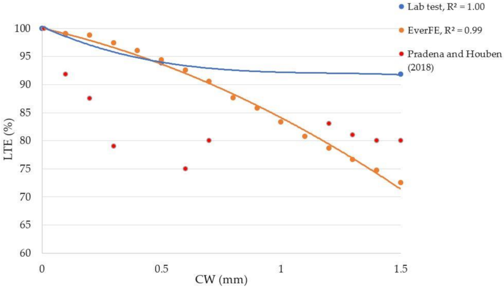
3.2. The LTE–CW Relation

The test solves the difficulty of characterizing the LTE–CW relation in a traditional concrete laboratory, where resources for the performance of complex tests may be limited. Consequently, it allows the development of the LTE–CW relation through an accessible process that involves fewer resources than the ones that are conventionally required. In effect, the sustainable and accessible approach adopted in the proposal represents a paradigm shift compared to the traditional methods of joint performance evaluation. Moreover, it represents a promising solution for developing countries where resources are limited.
Since the structural design plays an important role in improving pavement sustainability [19], it is relevant to incorporate the LTE values that correspond to the local reality. In this sense, the proposed test is an improvement to the mechanistic empirical design methods, avoiding projections that are not necessarily valid for the conditions of a given region. This is especially relevant in short slab pavements, which have promising sustainable characteristics, and its application has been concentrated in developing countries [21,26,27,28].
Figure 7 shows the LTE–CW relation from three sources: the laboratory results with Aggregate 1, the measurements over short slab sections recorded by Pradena and Houben [28], and the estimation with the software of finite elements for jointed concrete pavement, EverFE. All of the results correspond to a maximum aggregate size of 40 mm. The graph of Figure 7 indicates that the software cannot fully represent the contribution of the aggregate quality in the LTE–CW relation. In contrast, when comparing field and laboratory data, a similar LTE–CW trend is observed, even though the LTE values are not equal.
The difference in LTE values can be explained by the controlled laboratory conditions, which allow better transfer. In fact, the aggregate interlock mechanism is based on the irregularities on the crack faces, and, especially at in-service pavements, the cracks can be formed following a regular or irregular pattern. Hence, due the irregular nature of the phenomenon, it is possible to find variations in the LTE values for a specific CW [46].
As a general proposal to estimate the LTE–CW relation, the results obtained for Aggregate 1 were complemented with the results presented by Pradena et al. [46] and Pradena et al. [53]. These studies were selected because they also use Chilean aggregates characterized by their good hardness. Although they did not directly perform LA tests, the studies carried out by Achurra [83] indicate LA values lower than 15%. In addition, all of the aggregates meet the minimum threshold of 50% crushed particles [56].
In order to take into account the difference between laboratory and field values, a Safety Factor (SF) is applied. The factor was calculated as shown in Equation (2), and relates, for the n number of CWs evaluated, the average LTE laboratory values (LTElab) with the combined average of the field LTE [28] and the LTE estimated by EverFe (LTEm):
SF = LTE m LTE lab n
The laboratory LTE values were divided into two zones where different SF were applied. The first zone covers CW of up to 0.6 mm, and corresponds to the region where the LTE decreases as the CW increases. In this case, a, SF of 0.98 was applied. The second zone corresponds to the CW range between 0.7 mm and 1.5 mm, where the LTE shows a stable behaviour. In this case, a SF of 0.87 was used.
From the logarithmic regression analysis of the adjusted laboratory LTE values, Equation (3) is obtained in order to estimate the LTE in relation to the CW and properties typically used in traditional concrete laboratories:
LTE = 3.25 ln CW + 1.65 ln TM + 5.91 ln LA 0.16 ln CP + 63.47
where CW represents the Crack Width in mm, MS is the Maximum Size of the aggregate in mm, LA is the Los Angeles value, and CP is the Crushed Particle value. The influence of the CW and the aggregate properties on the aggregate interlock mechanism capacity was described in the Section 2.2 and Section 3.1. The R-square of Equation (3) is 0.82.
As Equation (3) incorporates an SF related to the variations that it is possible to obtain in the field, the LTE estimation is lower than the one from the laboratory. However, it is important to highlight that the LTE value for the maximum CW of 1.5 mm is considerably higher than 70%, which is the recommended value for adequate pavement performance (Figure 8).
In case the test to develop the LTE–CW relation cannot be performed, this equation is a valid alternative for aggregates that are similar to those used in this study, i.e., with good hardness according to an LA test. As previously mentioned, it is possible to highlight that Equation (3) estimates the LTE as a function of aggregate properties that it is feasible to evaluate in traditional concrete laboratories.

3.3. Sustainability Analysis Results

The results of the sustainability analysis are divided in two classes: Environmental Impact and Human Health. Among the environmental impacts, it is possible to find acidification, ecotoxicity, eutrophication, global warming, ozone depletion, and photochemical oxidation. The Human health category includes carcinogenics, non-carcinogenics, and respiratory effects aspects [73]. Figure 9 presents the emissions for each category obtained as the average of the results of the 18 routes selected for the analysis. In all of the cases, the short slab JPCP generates lower impacts. Furthermore, the results were subjected to a Mann–Whitney U test. In all cases, the test indicated significant differences between short slab JPCP and traditional JPCP for a 2-tailed test at the p < 0.05 level of probability.
Figure 10 presents the emissions reduction (in percentage) for all of the categories. The reduction of these indicators reflects that short slab pavements contribute to a more sustainable construction. Within the category related to the environmental impact, the greatest reductions were obtained for global warming, acidification and ozone depletion, with 33%, 27%, and 24%, respectively.
Reducing these emissions mitigates the effects of global warming, which contributes to increases in the atmospheric temperature and influences climate change patterns. Additionally, the reduction of acidification counteracts the formation of acid rain, fog, dry depositions, and damage to structures. Finally, the reduction of ozone depletion mitigates the increase of biologically harmful solar ultraviolet radiation [73,84].
Additionally, the results show that short slab pavements are also reducing the exposure to pollutants that produce carcinogenic, non-carcinogenic and respiratory effects. In effect, the Human Health categories decrease between 23% and 26%.
The visible advantages of short slabs are related to their ability to maintain a similar performance to a traditional JPCP while using thinner slabs. This reduction means less consumption of cement, which is the main generator of emissions. In effect, the TRACI evaluation reveals that, for both types of pavements, cement production contributes significantly to pavement emissions, for instance, Global Warming (Table 4). The percentage of cement’s contribution is higher in short slab pavements. This is because short slabs do not require a joint sealing material [21], which also contributes to the generation of harmful emissions. In the short slabs of Table 3, the average cement consumption decreases by 25 m3. This represents 180 m3 of concrete, which is equivalent to 26 concrete mixers of 7 m3 capacity. Therefore, the short slabs not only save approximately 20% of the construction costs [21], but also reduce the impact of the emissions produced by pavement construction.
In order to ensure the environmental advantages of short slab JPCP, the activation of the contraction joints is fundamental, i.e., cracks must be produced under the original saw-cutting at every joint. Otherwise, the slabs are not necessarily short, and they can basically result in traditional slabs with less thickness than that which is required for an adequate performance, compromising the structure integrity and invalidating the benefits that this paving alternative can achieve.

4. Conclusions

This article proposed a method to develop the response of the LTE in relation to the direct cause of its performance, i.e., the CW. The proposal aimed to avoid the investment of large financial resources, equipment, and materials, while generating a precise definition of the LTE for the case study. Then, it focuses on developing the LTE–CW relation through a sustainable and accessible process. In this context, the method comprised a small-scale test using equipment that is available in traditional concrete laboratories. Furthermore, the proposal included the LTE–CW characteristic curve for aggregates similar to those used in the study.
The sustainable and accessible approach adopted in the proposal represents a paradigm shift compared to the traditional methods of joint performance evaluation. This is especially relevant in developing countries where resources are scarce. In addition, the LTE–CW characteristic curve contributes to sustainable design by defining the LTE values for the expected in-service conditions.
Incorporating the LTE–CW relation into the JPCP structural design methods contributes to ensuring the good performance of the in-service pavement. This relation is especially relevant for short slab pavements, where the main load transfer mechanism is the aggregate interlock. Furthermore, the design hypothesis proposes a new traffic load configuration and curling reduction when the slabs are effectively short, which allow us to reduce the slab thickness while maintaining a performance that is similar to a traditional pavement. However, this is valid when the in-service pavement conditions are close to those of the design. When this happens, it is possible to save approximately 20% of the construction cost, and to reduce the impact of the emissions generated. Indeed, the sustainability analysis confirmed that, compared to traditional JPCP, short slabs reduce up to 33% of environmental emissions and up to 26% of adverse human health effects. In effect, thinner slabs mean a lower consumption of concrete, and especially cement, which is the main generator of emissions.
From a sustainable engineering approach, the aggregate applied can contribute to the performance of JPCP short slabs. The LTE results for the harder aggregate show a better performance than the less hard aggregate. Additionally, under overweight conditions, the harder aggregate produces only a slight reduction of the LTE values when compared to a standard axle (80 kN). As overweight cases are not unusual in developing countries, the use of hard aggregates ensures a stable LTE performance. This contributes to the reduction of the probability of structural failure, maintaining an adequate level of service, and reducing the need for significant maintenance.
The benefits proposed by short slab pavements are only valid if the design hypotheses are fulfilled. In particular, cracking under the contraction joint is especially relevant. If most of the joints are activated, then the slabs are indeed short, the CW is less than 1.5 mm, and the expected LTE corresponds to the applied design. Furthermore, the new traffic load configurations and the curling reduction are produced as well.

Author Contributions

Conceptualization, M.P. and A.C.; methodology, M.P. and A.C.; formal analysis, M.P. and A.C.; investigation, A.C..; writing—original draft preparation, A.C.; writing—review and editing, A.C.; supervision, M.P. All authors have read and agreed to the published version of the manuscript.

Funding

This research received no external funding.

Acknowledgments

The authors acknowledge the contribution of Departamento de Ingeniería Civil Mecánica (Flores, Medina and Canales) and Departamento de Ingeniería Civil Minas (Gómez), Facultad de Ingeniería, Universidad de Concepción for providing part of the equipment used in this research.

Conflicts of Interest

The authors declare no conflict of interest.

References

  1. Wang, H. Life-cycle analysis of repair of concrete pavements. In Eco-Efficient Repair and Rehabilitation of Concrete Infrastructures; Woodhead Publishing: Cambridge, UK, 2018; pp. 723–738. [Google Scholar]
  2. Sánchez, R.F.; Meseguer, A.G. Pavimentos de hormigón en vías urbanas. Inf. Constr. 1971, 23, 61–73. (In Spanish) [Google Scholar]
  3. Smith, T.; Maillard, P. Sustainable Benefits of Concrete Pavement. In Proceedings of the 42e Congres Annuel de l’AQTR-Defi, Transport Durable, Montréal, OC, Canada, 2–4 April 2007. [Google Scholar]
  4. Delatte, N. Concrete Pavement Design, Construction, and Performance, 1st ed.; Taylor & Francis: New York, NY, USA, 2008. [Google Scholar]
  5. Díaz-Minguela, J.; Hacar, F. Estudio de los pavimentos de túneles carreteros: Ventajas de los pavimentos de hormigón frente a los bituminosos. Obras y Proyectos 2018, 23, 87–95. (In Spanish) [Google Scholar] [CrossRef]
  6. Khan, M.; Ali, M. Effectiveness of hair and wave polypropylene fibers for concrete roads. Constr. Build. Mater. 2018, 166, 581–591. [Google Scholar] [CrossRef]
  7. Mohod, M.V.; Kadam, K.N. A comparative study on rigid and flexible pavement: A review. IOSR JMCE 2016, 13, 84–88. [Google Scholar]
  8. Kline, J.; Barcelo, L. Cement and CO2, a victim of success! In Proceedings of the IEEE-IAS/PCA 54th Cement Industry Technical Conference, San Antonio, TX, USA, 14–17 May 2012; pp. 1–14. [Google Scholar]
  9. Monteiro, P.J.M.; Miller, S.A.; Horvath, A. Towards sustainable concrete. Nat. Mater. 2017, 16, 698–699. [Google Scholar] [CrossRef]
  10. Mindess, S. Sustainability of concrete. In Developments in the Formulation and Reinforcement of Concrete, 2nd ed.; Woodhead Publishing: Vancuver, BC, Canada, 2019; pp. 3–17. [Google Scholar]
  11. Fernandez, A.; Leung, Y. Technology Roadmap-Low-Carbon Transition in the Cement Industry. 2018. International Energy Agency. Available online: https://webstore.ie.org/technologyroadmap-low-carbon-transition-in-the-cement-industry (accessed on 6 May 2020).
  12. Lepech, M.D.; Keoleian, G.A.; Li, V.C.; Qian, S. Design of green engineered cementitious composites for pavement overlay applications. In Proceedings of the 1st International Sympoium on Life Cycle Civil Engineering, Varenna, Italy, 10–14 June 2008; pp. 837–842. [Google Scholar]
  13. Potgieter, J.H. An Overview of Cement production: How “green” and sustainable is the industry? Environ. Manag. Sustain. Dev. 2012, 1, 14. [Google Scholar] [CrossRef] [Green Version]
  14. Opoku, A.; Ahmed, V. Embracing sustainability practices in UK construction organizations. Built Environ. Proj. Asset Manag. 2014, 4, 90–107. [Google Scholar] [CrossRef]
  15. World Commission on Environment and Development. Our Common Future: Report of the World Commission on Environment and Development; Oxford University Press: Oxford, UK, 1987. [Google Scholar]
  16. Rosen, M.A. Engineering Sustainability: A Technical Approach to Sustainability. Sustainability 2012, 4, 2270–2292. [Google Scholar] [CrossRef] [Green Version]
  17. Brunatti, C.; Fernandez, L. El Pavimento de Hormigón. Un Camino Sustentable. In Proceedings of the I Congreso Hormigón Premezclado de las Américas, Mar del Plata, Argentina, 8–10 November 2010. (In Spanish). [Google Scholar]
  18. Plati, C. Sustainability factors in pavement materials, design, and preservation strategies: A literature review. Constr. Build. Mater. 2019, 211, 539–555. [Google Scholar] [CrossRef]
  19. Van Dam, T.; Taylor, P.; Fick, G.; Gress, D.; VanGeem, M.; Lorenz, E. Sustainable Concrete Pavements: A Manual of Practice; National Concrete Pavement Technology Center, Iowa State University: Ames, IA, USA, 2012. [Google Scholar]
  20. Covarrubias, T.J.P.; Covarrubias, J.P. TCP design for thin concrete pavements. In Proceedings of the 9th International Conference on Concrete Pavements, San Francisco, CA, USA, 17–21 August 2008. [Google Scholar]
  21. Covarrubias, J.P. Design of concrete pavement with optimized slab geometry. Rev. Ing. Constr. 2012, 27, 181–197. [Google Scholar]
  22. Roesler, J.R.; Cervantes, V.G.; Amirkhanian, A. Accelerated performance testing of concrete pavement with short slabs. Int. J. Pavement Eng. 2012, 13, 494–507. [Google Scholar] [CrossRef]
  23. ICH. Available online: https://ich.cl/pavimentando/noticias-pavimentando/experiencia-de-chile-con-los-pavimentos-de-losas-cortas/ (accessed on 14 June 2020).
  24. Revista EMB Construcción. Available online: http://www.emb.cl/construccion/articulo.mvc?xid=3280&edi=154&xit=augusto-holmberg-gerente-general-ich-el-repunte-del-hormigon-en-la-industria-de-pavimentos (accessed on 14 June 2020). (In Spanish).
  25. Skrzypczak, I.; Radwański, W.; Pytlowany, T. Durability vs technical—The usage properties of road pavements. E3S Web Conf. 2018, 45, 00082. [Google Scholar] [CrossRef] [Green Version]
  26. Chávez, O. Losas Cortas: Una experiencia en Nicaragua. In Proceedings of the VII Congreso Nacional de Ingeniería Civil, Managua, Nicaragua, 17–18 October 2013. (In Spanish). [Google Scholar]
  27. Salsilli, R.; Wahr, C.; Delgadillo, R.; Huerta, J.; Sepúlveda, P. Field performance of concrete pavements with short slabs and design procedure calibrated for Chilean conditions. Int. J. Pavement Eng. 2014, 16, 363–379. [Google Scholar] [CrossRef]
  28. Pradena, M.; Houben, L. Load Transfer-Crack Width Relation of Non-Dowelled Jointed Plain Concrete Short SLABS. Balt. J. Road Bridge Eng. 2018, 13, 40–45. [Google Scholar] [CrossRef] [Green Version]
  29. Covarrubias, J.P. Design of concrete slabs with optimized geometry. In Proceedings of the 2nd International Conference on Best Practices for Concrete Pavements, Florianopolis, Brazil, 2–4 November 2011. [Google Scholar]
  30. Bordelon, A.C.; Roesler, J.; Hiller, J.E. Mechanistic-Empirical Design Concepts for Jointed Plain Concrete Pavements in Illinois; Illinois Center for Transportation (ICT): Urbana, IL, USA, 2009. [Google Scholar]
  31. Wadkar, A.; Mehta, Y.; Cleary, D.; Guo, E.; Musumeci, L.; Zapata, A.; Kettleson, W. Load-Transfer Efficiencies of Rigid Airfield Pavement Joints Based on Stresses and Deflections. J. Mater. Civ. Eng. 2011, 23, 1171–1180. [Google Scholar] [CrossRef]
  32. Snyder, M.B. Guide to Dowel Load Transfer System for Jointed Concrete Roadway Pavements; Institute for Transportation at Iowa State University; National Concrete Consortium: Ames, IA, USA, 2011. [Google Scholar]
  33. Maitra, S.R.; Reddy, K.S.; Ramachandra, L.S. Load Transfer Characteristics of Aggregate Interlocking in Concrete Pavement. J. Transp. Eng. 2010, 136, 190–195. [Google Scholar] [CrossRef]
  34. Nowlen, W.J. Influence of Aggregate Properties on Effectiveness of Interlock Joints in Concrete Pavements. J. PCA Res. Dev. Lab. 1968, 10, 2–8. [Google Scholar]
  35. Walraven, J.C. Aggregate Interlock: A Theoretical and Experimental Analysis. Ph.D. Thesis, The Delft University of Technology, Delft, The Nederlands, October 1980. [Google Scholar]
  36. Wattar, S.W. Aggregate Interlock Behavior of Large Crack Width Concrete Joints in PCC Airport Pavements. Ph.D. Thesis, The University of Illinois at Urbana-Champaign, Champaign County, IL, USA, 2002. [Google Scholar]
  37. Byrum, C.R.; Barton, P.J.; Rollings, R.S.D.; Ioannides, A.M.; Gemayel, C.A.; Tayabji, S. Joint Load Transfer in Concrete Airfield Pavements: Final Report; Innovative Pavement Research Foundation Report IPRF-01-G-002-05-2; IPRF: Rosemont, IL, USA, 2011. [Google Scholar]
  38. Söderqvist, J. Design of Concrete Pavements: Design Criteria for Plain and Lean Concrete. Ph.D. Thesis, Royal Institute of Technology, Stockholm, Sweden, November 2006. [Google Scholar]
  39. Stet, M.J.A.; Leest, A.; Frénay, J.W. Dutch design tool for jointed and continuously reinforced concrete road pavements. In Proceedings of the 10th International Symposium on Concrete Roads, Brussels, Belgium, 18–22 September 2006. [Google Scholar]
  40. Houben, L.J.M. Structural Design of Pavements. Part IV: Design of Concrete Pavements; Lecture Notes CT4860; The Delft University of Technology: Delft, The Netherlands, 2006. [Google Scholar]
  41. Hiller, J.E. Development of Mechanistic-Empirical Principles for Jointed Plain Concrete Pavement Fatigue Design. Ph.D. Thesis, University of Illinois at Urbana-Champaign, Champaign, IL, USA, October 2007. [Google Scholar]
  42. Chilean Highway Agency. Difusión Nuevas Tecnologías y Especificaciones Técnicas Manual Anexo N°1: Método de Diseño de Pavimento de Hormigón con Losas de Espesor Optimizado; Ministerio de Obras Públicas: Santiago, Chile, 2012. (In Spanish) [Google Scholar]
  43. Revista Obras Públicas. Resultados observados en nuevas tecnologías de pavimentos de hormigón. Rev. Obras Públicas 2020, 53, 34–37. [Google Scholar]
  44. Colley, B.E.; Humphrey, H.M. Aggregate Interlock at Joints in Concrete Pavements; Highway Research Record 189; HRB National Research Council: Washington, DC, USA, 1967; Volume 189, pp. 1–18. [Google Scholar]
  45. Jensen, E.A. Mechanism of load transfer-crack width relation in JPCP: Influence of coarse aggregate properties. In Proceedings of the 7th International Conference on Concrete Pavements. The Use of Concrete in Developing Long-Lasting Pavement Solutions for the 21st Century, International Society for Concrete Pavements, Orlando, FL, USA, 9–13 September 2001. [Google Scholar]
  46. Pradena, M.; Houben, L.; César, A. Laboratory Characterization of the Load Transfer-Crack Width Relation for Innovative Short Concrete Slabs Pavements. Balt. J. Road Bridge Eng. 2020, 15, 232–250. [Google Scholar] [CrossRef]
  47. Abraham, M.A.; Nguyen, N. “Green engineering: Defining the principles”—Resdts from the sandestin conference. Environ. Prog. 2003, 22, 233–236. [Google Scholar] [CrossRef]
  48. Allen, D.T.; Shonnard, D.R. Sustainable Engineering: Concepts, Design, and Case Studies; Prentice Hall: Upper Saddle River, NJ, USA, 2012. [Google Scholar]
  49. ASTM. Standard Test Method for Flexural Strength of Concrete (Using Simple Beam with Third-Point Loading); ASTM C78; ASTM: West Conshohocken, PA, USA, 2018. [Google Scholar]
  50. Ramirez, L.C. Concrete Mixer Properties Affecting the Aggregate Interlock Mechanism of Joints and Cracks for Rigid Pavement Systems. MSc Thesis, University of Pittsburgh, Pittsburgh, PA, USA, November 2010. [Google Scholar]
  51. Thompson, I. Use of Steel Fibres to Reinforce Cement Bound Roadbase. Ph.D. Thesis, The University of Nottingham, Nottingham, UK, May 2001. [Google Scholar]
  52. Arnold, S.; Fleming, P.R.; Austin, S.; Robins, P. A test method and deterioration model for joints and cracks in concrete slabs. Cem. Concr. Res. 2005, 35, 2371–2383. [Google Scholar] [CrossRef] [Green Version]
  53. Pradena, M.; Houben, L.; César, A. Experimental evaluation of load transfer efficiency of non-dowelled concrete pavements. Gradevinar. accepted.
  54. Osman, O.; El Ghazolly, M.; Mousa, R. Impact of increasing legal axle loads on truck factor in Egypt; Taylor & Francis Group: London, UK, 2009; pp. 709–718. [Google Scholar]
  55. Macea, L.F.; Fuentes, L.G.; Alvarez, A.E. Evaluación de factores camión de los vehículos comerciales de carga que circulan por la red vial principal colombiana. Rev. Fac. Ing. 2016, 66, 57–69. (In Spanish) [Google Scholar]
  56. Hanekom, A.C.; Horak, E.; Visser, A.T. Comparison of South African and American Aggregate Interlock Efficiency at Concrete Pavement Joints. In Proceedings of the 16th ASCE Engineering Mechanics Conference, Seattle, WA, USA, 16–18 July 2003. [Google Scholar]
  57. Neville, A.M. Properties of Concrete; Longman: London, UK, 1995; Volume 4. [Google Scholar]
  58. Tunc, E.T.; Alyamac, K.E. A preliminary estimation method of Los Angeles abrasion value of concrete aggregates. Constr. Build. Mater. 2019, 222, 437–446. [Google Scholar] [CrossRef]
  59. ASTM. Resistance to Degradation of Large Size Coarse Aggregate by Abrasion and Impact in the Los Angeles Machine; ASTM C535; ASTM International: West Conshohocken, PA, USA, 2016. [Google Scholar]
  60. ASTM. Standard Test Method for Compressive Strength and Elastic Moduli of Intact Rock Core Specimens Under Varying States of Stress and Temperatures; ASTM D7012; ASTM International: West Conshohocken, PA, USA, 2014. [Google Scholar]
  61. Deere, D.U.; Miller, R.P. Engineering Classifications and Index Properties for Intact Rock; Technical Report No. AFWL-TR 65-116; Air Force Weapons Laboratory, Kirtland Air Force Base: Albuquerque, NM, USA, 1966. [Google Scholar]
  62. Chilean Highway Agency. Highways Manual; Ministry of Publics Works: Santiago, Chile, 2019. (In Spanish) [Google Scholar]
  63. Salsilli, R.; Wahr, C. Trends in Concrete Pavements. In Proceedings of the Seminar New Challenges and Trends in Concrete Pavements, Santiago, Chile, 9 November 2010. (In Spanish). [Google Scholar]
  64. Salgado, M. Analysis and Prediction of the Behaviour of Semi-Rigid Short Slabs Concrete Pavements. In Proceedings of the International Seminar Latest Advances in Design and Construction of Concrete Pavements, Buenos Aires, Argentina, 9–10 May 2011. (In Spanish). [Google Scholar]
  65. ISO. ISO 14040: Environmental management—Life Cycle Assessment—Principles and Framework; ISO: Geneva, Switzerland, 2006. [Google Scholar]
  66. ISO. ISO 14044: Environmental Management—Life Cycle Assessment—Requirements and Guidelines; ISO: Geneva, Switzerland, 2006. [Google Scholar]
  67. Harvey, J.; Meijer, J.; Ozer, H.; Al-Qadi, I.L.; Saboori, A.; Kendall, A. Pavement Life Cycle Assessment Framework (No. FHWA-HIF-16-014); Federal Highway Administration: Washington, DC, USA, 2016. [Google Scholar]
  68. Cebrián, D.; Garraín, D.; Vidal, R.; Abad, J.; París, A. Free LCA: The use of ELCD in the design stage. In Proceedings of the 13th International Congress on Project Engineering, Bajadoz, Spain, 8–10 July 2009. [Google Scholar]
  69. ÖKOBAUDAT Database. Available online: https://oekobaudat.de/ (accessed on 16 May 2020).
  70. EN 15804. Sustainability of Construction Work—Environmental Product Declarations—Core Rules for the Product Category of Construction Products; European Committee for Standardization: Brussels, Belgium, 2012. [Google Scholar]
  71. EPA 2002 U.S. Exhaust and Crankcase Emissions Factors for Nonroad Engine Modelling—Compression-Ignition; Report No. NR-009b; Assessment and Standards Division, Office of Transportation and Air Quality: Washington, DC, USA, 2002. [Google Scholar]
  72. GreenDelta. Available online: http://www.openlca.org/download/ (accessed on 5 April 2020).
  73. Bare, J.C.; Norris, G.A.; Pennington, D.W.; McKone, T. TRACI: The tool for the reduction and assessment of chemical and other environmental impacts. JIE 2003, 6, 49–78. [Google Scholar] [CrossRef]
  74. Shi, X.; Mukhopadhyay, A.; Zollinger, D.; Grasley, Z. Economic input-output life cycle assessment of concrete pavement containing recycled concrete aggregate. J. Clean. Prod. 2019, 225, 414–425. [Google Scholar] [CrossRef]
  75. Harvey, J.; Wang, T.; Lea, J. Application of LCA results to network-level highway pavement management. In Climate Change, Energy, Sustainability and Pavements; Springer: Berlin/Heidelberg, Germany, 2014; pp. 41–73. [Google Scholar]
  76. Yang, R.Y. Development and Implementation of Comprehensive Regionalized Pavement Life-Cycle Assessment. Ph.D. Thesis, University of Illinois at Urbana-Champaign, Champaign, IL, USA, April 2017. [Google Scholar]
  77. Brink, A.; Horak, E.; Visser, A. Improvement of aggregate interlock equation used in mechanistic design software. Int. J. Concr. Pavements 2005, 1, 1–22. [Google Scholar]
  78. Barman, M. Joint Performance Characterization of Bonded Whitetopping Overlays. Ph.D. Thesis, University of Pittsburgh, Pittsburgh, PA, USA, 2014. [Google Scholar]
  79. Hu, C.H.; Ma, X.Z. Load Transfer Behavior of Cracking for Cement Concrete Pavement. Adv. Mater. Res. 2015, 1120, 1496–1500. [Google Scholar] [CrossRef]
  80. Buch, N.; Frabizzio, M.A.; Hiller, J.E. Impact of coarse aggregates on transverse crack performance in jointed concrete pavements. ACI Mater. J. 2000, 97, 325–332. [Google Scholar]
  81. Mulyono, A.T.; Parikesit, D.; Antameng, M.; Rahim, R. Analysis of loss cost of road pavement distress due to overloading freight transportation. J. East Asia Soc. Transp. Stud. 2009, 8, 19–30. [Google Scholar]
  82. Macea-Mercado, L.F.; Morales, L.; Márquez-Díaz, L.G. Un sistema de gestión de pavimentos basado en nuevas tecnologías para países en vía de desarrollo. Ing. Investig. Tecnol. 2016, 17, 223–236. [Google Scholar] [CrossRef] [Green Version]
  83. Achurra, S. Procedure to Measure and Control of the Superficial Friction in Chilean Pavements. Master’s Thesis, Catholic University of Chile, Santiago, Chile, July 2009. (In Spanish). [Google Scholar]
  84. Slaper, H.; Velders, G.J.; Daniel, J.S.; De Gruijl, F.R.; Van der Leun, J.C. Estimates of ozone depletion and skin cancer incidence to examine the Vienna Convention achievements. Nature 1996, 384, 256–258. [Google Scholar] [CrossRef]
Figure 1. Two cracks induction process: (a) mold preparation; (b) notched sample; (c) sample with two induced cracks.
Sustainability 12 09153 g001
Figure 2. Laboratory test setup: (a) sample configuration; (b) final setup.
Sustainability 12 09153 g002
Figure 3. Prototype test setup.
Sustainability 12 09153 g003
Figure 4. Sustainability evaluation from a cradle-to-laid approach.
Sustainability 12 09153 g004
Figure 5. LTE–CW relation: (a) Aggregate 1, 20 mm; (b) Aggregate 1, 40 mm; (c) Aggregate 2, 20 mm; (d) Aggregate 2, CW 40 mm.
Sustainability 12 09153 g005aSustainability 12 09153 g005b
Figure 6. LTE–CW in relation to the axle load: (a) Aggregate 1, 20 mm; (b) Aggregate 1, 40 mm; (c) Aggregate 2, 20 mm; (d) Aggregate 2, 40 mm.
Sustainability 12 09153 g006aSustainability 12 09153 g006b
Figure 7. LTE–CW relation comparison, Aggregate 1, 40 mm.
Sustainability 12 09153 g007
Figure 8. LTE–CW relation laboratory test and Equation (3) comparison: Aggregate 1, 40 mm.
Sustainability 12 09153 g008
Figure 9. LCA TRACI results: (a) Acidification; (b) Ecotoxicity; (c) Eutrophication; (d) Global Warming; (e) Ozone Depletion; (f) Photochemical Oxidation; (g) Carcinogenics; (h) Non-carcinogenics; (i) Respiratory Effects.
Sustainability 12 09153 g009aSustainability 12 09153 g009b
Figure 10. Percentage of emission reduction with short slabs.
Sustainability 12 09153 g010
Table 1. Load magnitudes considered in the experiments.
Load Test (kN)Vehicle Axle (kN)Stress Produced (kPa)
880224
10100266
12120320
Table 2. Aggregates’ properties.
PropertiesAggregate 1Aggregate 2
LA (%)1227
UCS (MPa)104.8358.94
CP (%)75100
Table 3. Traditional and short slab JPCP’s thickness (mm).
RouteTraditional JPCPShort Slabs JPCP
1220170
2220160
3180150
4180100
5150100
6180130
7220150
8300220
9250180
10260200
11240180
12250200
13165125
14260180
15180150
16250180
17200150
18280200
Table 4. Percentage contribution to Global Warming, %.
PropertiesTraditional PavementShort Slab Pavement
Portland Cement80.5788.66
Gravel5.756.35
Sand2.843.13
Diesel0.461.44
Joint seal9.99-
Others0.380.42
Publisher’s Note: MDPI stays neutral with regard to jurisdictional claims in published maps and institutional affiliations.

