Notwithstanding a clear global trend towards the increasing development and implementation of sustainable urban drainage systems, this issue is not addressed on a widespread scale at the moment in Poland, where a conventional stormwater management approach still remains the most common in urban management. In Poland, which has an unfavorable water balance, rainwater still constitutes an unappreciated contribution to the urban water cycle and is still mostly treated as a nuisance to be disposed of, and discharged as quickly as possible to a receiving water body. Only recently, following the momentum of predicted effects of climate change, and the problem of a lowered groundwater table across the country [
43], is stormwater starting to be considered as a possible alternative resource. An analysis of national domestic water consumption trends showed that approximately 50% of public drinking-quality water consumption could be substituted by reused rainwater, with peak of about 65% in public buildings [
44].
Two case studies of sustainable stormwater solutions implemented in small buildings in the Kobierzyce commune in the Silesia Region of south Poland are presented and analyzed herein. These concern on-site retention and subsequent water reuse, and a rainwater infiltration garden installation, respectively.
3.1. Case Study 1: Onsite Rainwater Retention and Subsequent Reuse
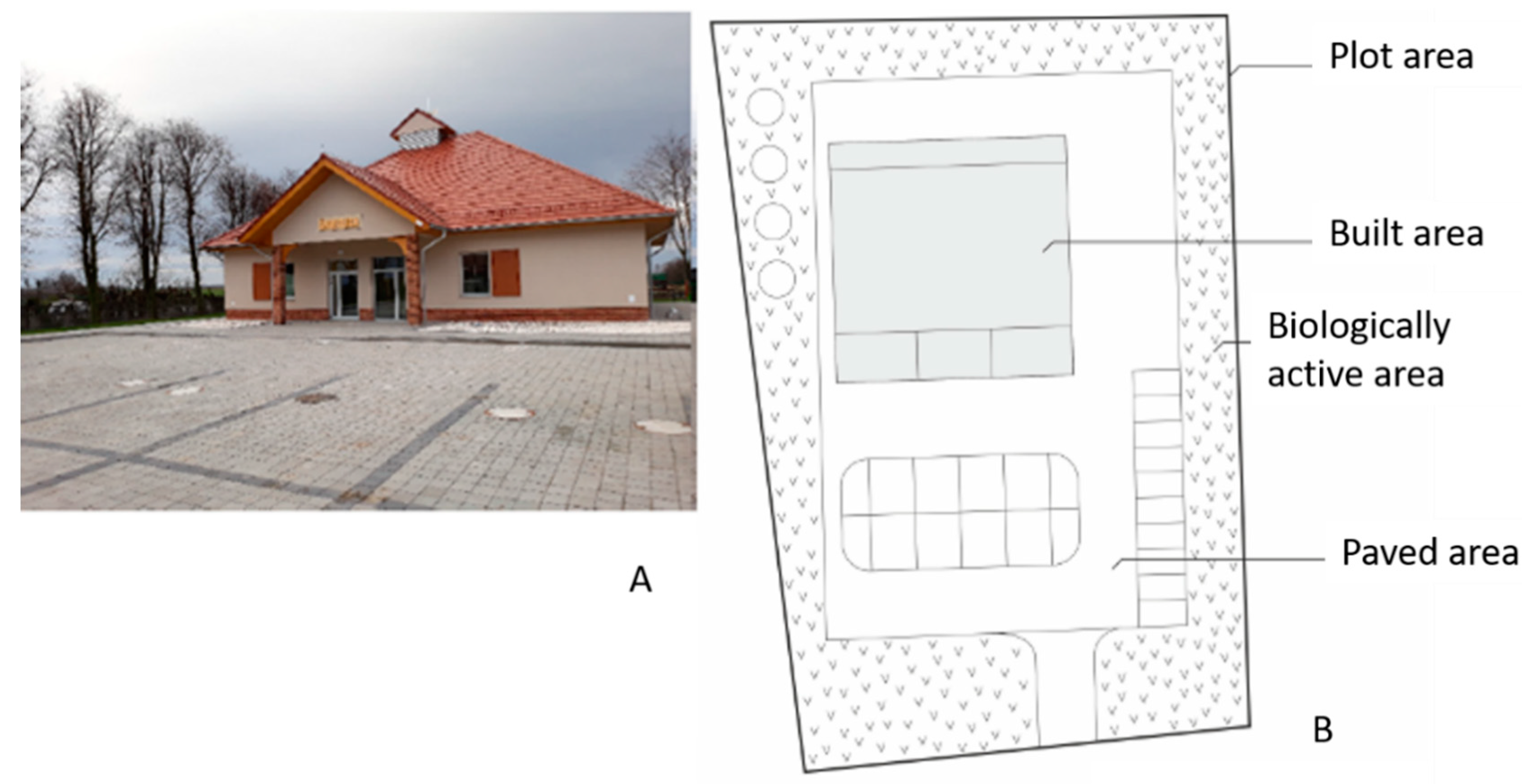
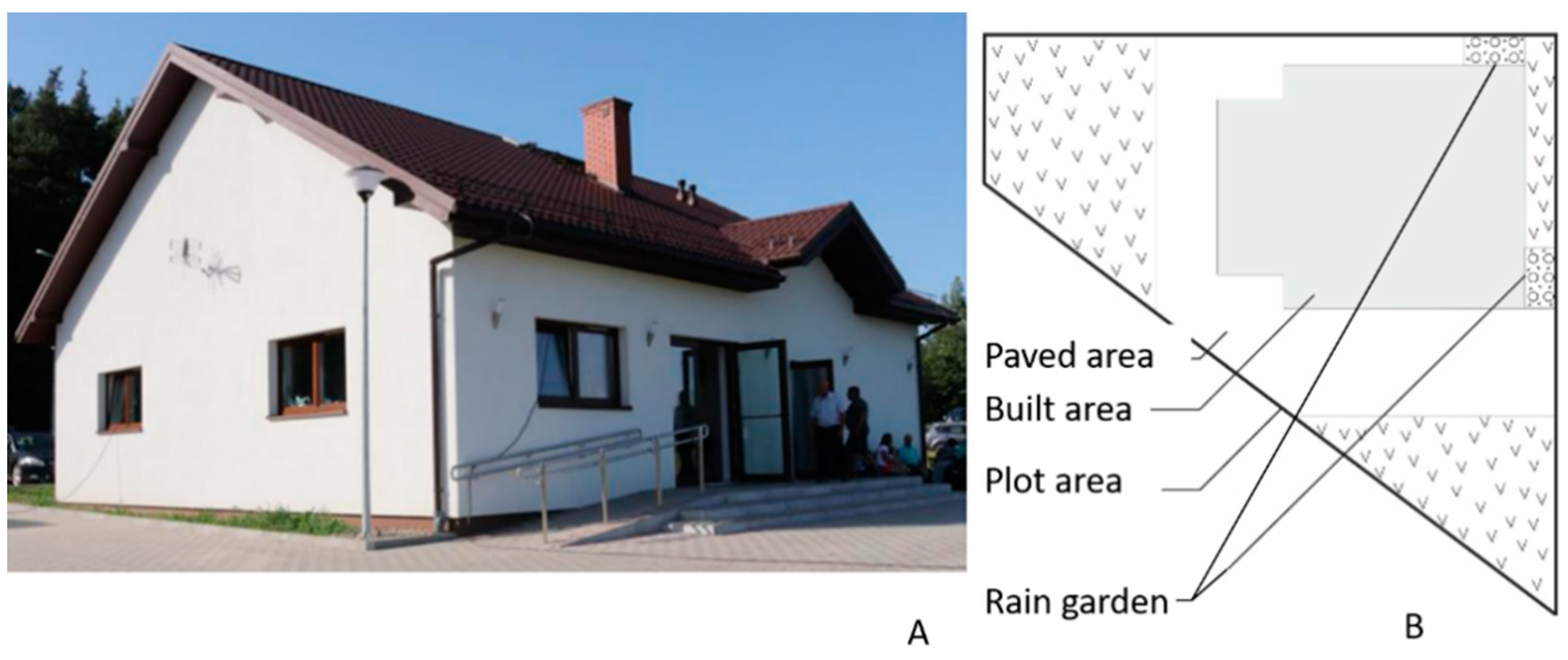
The first case examined concerns a community center building with playground and parking, built on the site of a demolished establishment, where a local rainwater retention system was implemented. The total plot area of 3300 m
2 consists of directly connected impervious areas (roof and parking) of about 700 m
2 (21% of the lot surface). Built area (including terrace) is 380 m
2, total paved surfaces 1500 m
2, playground 150 m
2, and biologically active area (lawns and trees) 1250 m
2 (37.88% of total) (
Figure 2). The organic soil layer consists of low-permeability compacted sand, clay and sandy loams. Groundwater occurs at a depth of 1.5–1.8 m below surface, and therefore is poorly suitable for stormwater infiltration.
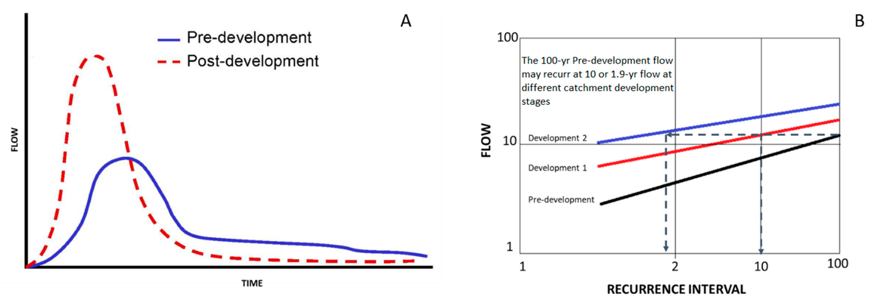
In the original site conditions, stormwater was discharged directly to a sewer network; with the increased impervious area (larger building and paved area), higher runoff and overflow events were expected. Aside from pure ecological considerations, the main factor suggesting the adoption of an alternative stormwater management solution was related to the increased fee for its discharge. During redevelopment, the site drainage was therefore re-designed with the implementation of a retention basin to reduce stormwater release into the sewer from the property area.
The design of the retention system is based on the estimate of the amount of rainwater and snowmelt on site: for small-scale solutions (e.g., single-family housing, service construction, single public facility building) as in the described case this does not require complex dynamic flow calculations, unlike the case of large catchments [
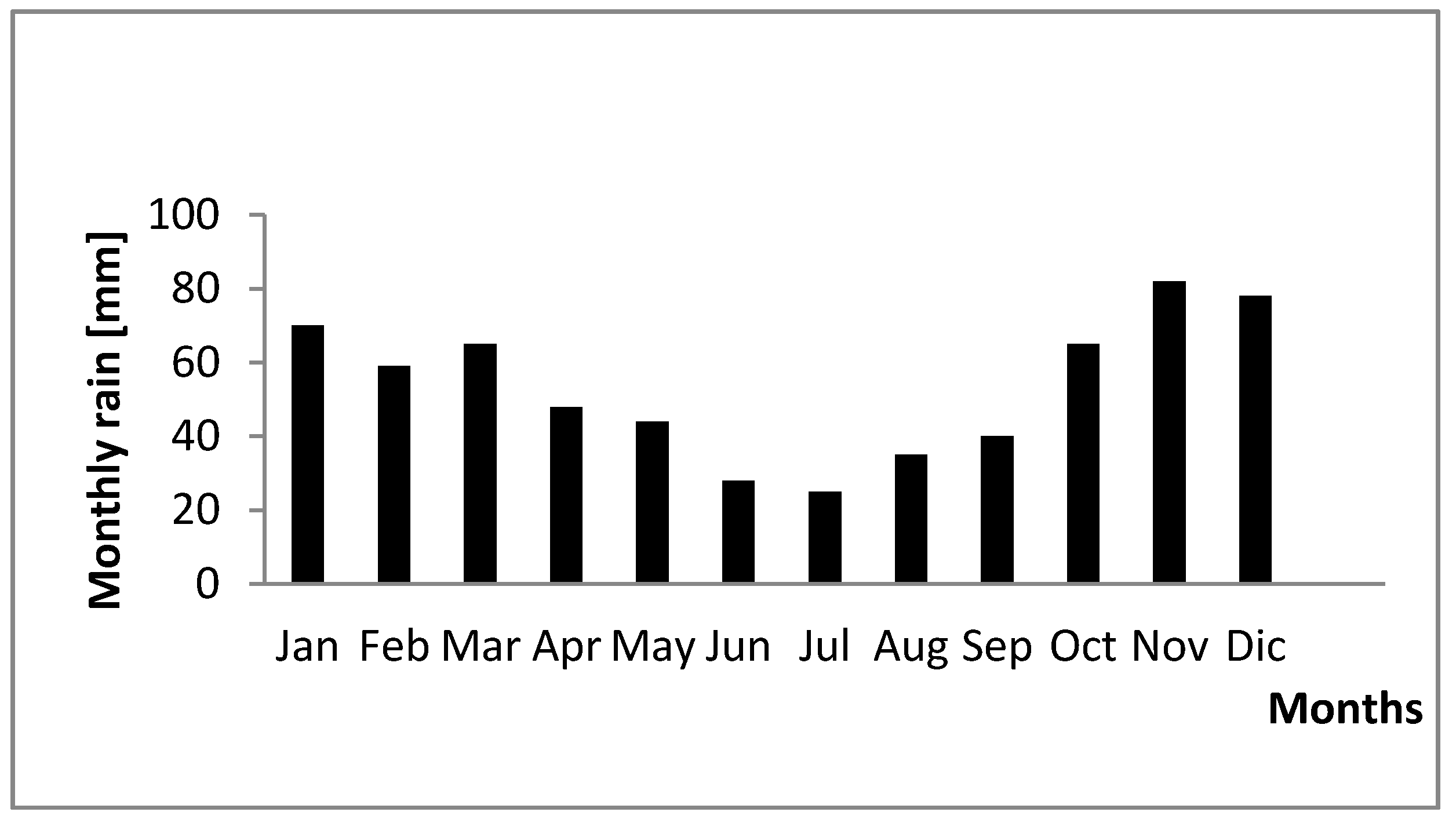
45]. The site’s 20-year average annual precipitation (rainwater plus snowmelt), obtained from records of a nearby meteorological station, was estimated at about 600 mm (
Figure 3). In the last two years, values of 812 mm and 544 mm were observed, respectively.
The widely used Polish standard (conforming to European standards) PN-EN 75 indicates the following formula for calculating the runoff rate for surfaces <10,000 m
2:
where
Q is the maximum flow (L/s),
Ψ the permeability coefficient,
I the rainfall intensity (per ha), and
A the area (ha) considered.
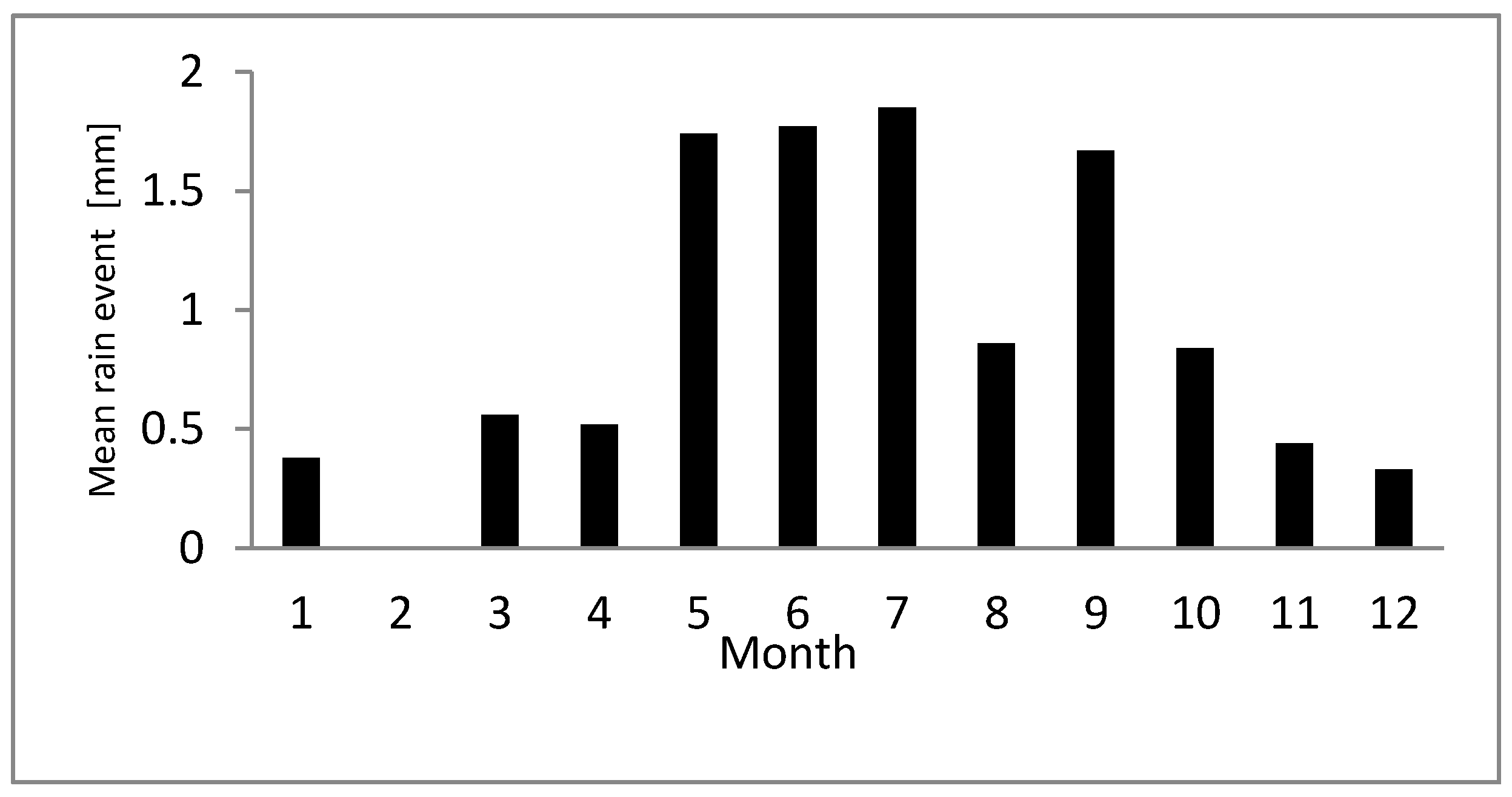
The maximum rainfall rate can be calculated using the Błaszczyk method, for 15-min events (
Figure 4) and areas with annual rainfall H < 800mm:
where
C is the return frequency during which rain occurs with duration
t and intensity
q, and
H the average annual rainfall, in mm.
The observed behavior of monthly and burst precipitation time series has significant seasonal variability, with relatively dry summers of intense, short rainfall events. This makes local storage an issue of primary relevance in runoff management. Total average runoff of 1134 and 642 m
3/year were thus calculated for parking area and roof. Based on the maximum value of 1.85 mm intensity for the 20-year 15-min event, runoff volumes of 27.75 m
3 and 11 m
3 were calculated for the parking and roof areas, respectively, and targeted for temporary storage. Excess runoff during the more intense events would be diverted to the sewer. Storage tank volume was determined by the practical formula [
46]:
where:
Vj indicates the unit retention volume (m
3),
Fzr the reduced area (ha) of the contributing surface,
qmax(t) the maximum unit rainfall intensity (L/ha) with duration t
d [min],
qdł maximum specific outflow from storage (L/ha),
fa a reduction factor (≤1), depending on corrivation time in the network,
tp (min) and the frequency of rainfall
C [years], and
fz a safety factor for volume exceedance (1.1–1.2).
Runoff management was thus reconfigured as follows: roof runoff directed immediately to underground storage (11 m3 capacity); runoff from car parking, processed in a class I oil separator according to PN-EN 858:2005 standard, to reduce residual concentration of petroleum substances below 5 mg/L. Parking runoff is conveyed by the site’s drainage network (137 m of DN400, 49 m of DN315, 54 m of DN200 and 30 m of DN160 pipes, for a total available free volume of 23.3 m3, enough to hold approximately 85% of the maximum parking runoff volume during and after the design event), and ends in the underground tank from which the excess overflows to the storm sewer. The maximum 15-min runoff calculated from (2) amounts to 132 L/s; the maximum downstream conveyance capacity of the drainage network is 14.3 L/s. A prefabricated oil separator, with integrated settling tank, type OKSYDAN-P 15 (OKSYDAN Sp.z.o.o, Gliwice, Poland)) with nominal capacity of 15 L/s and integrated settling tank of 1.5 m3 was installed upstream of the underground tank. Local prescriptions on maximum overflow into storm sewers prescribe a limit of 10 L/s, hence a flow regulator (AQUANTIS 330598, diam. 160 mm) was installed at the outlet of the tank.
Stored runoff is targeted for local non-potable reuse: green area watering, surface washing or car washing. According to locally adopted design criteria, the retention tank volume could be suitable to irrigate a green area close to 1000 m
2, as shown in
Table 2.
The underground tank, the pivot element of the system, is fitted with a replaceable cartridge filter (sieve size 25 μm) to retain suspended solids prior to overflow into the municipal storm system. The filter operates with a limited head loss (1–3 cm, depending on fouling), and does not require additional energy inputs, but it must be periodically replaced. A recirculation pump is provided to feed lawn irrigation and other reuse options. This design is able:
to reduce and delay runoff drainage into the sewer system;
to retain rainwater at source;
to infiltrate irrigation water, enhancing evapotranspiration from biologically-active surfaces;
to reuse retained water for local uses and reduce water bills;
to optimize storm sewer network operation, reducing flood risk in the neighboring area and pollution of receiving waters.
In addition to the reduction of costs associated with lower volumes of stormwater discharged into the drainage system, collected runoff can be used, according to local regulations, for non-potable purposes, thereby reducing water bills at the site. Drawbacks include the need for periodic cleaning of filters and gutters from debris. From a cost-balance standpoint, if runoff from impervious surfaces were to be discharged in full to the sewage system, as in a conventional system, costs of discharge fess would be applicable. This amount can be determined based on existing regulation as 0.34 € per square meter-year of impervious area, at the amount of about 230 € per year. An additional fixed fee for discharge is assessed at about 46 € per year. With the designed system, the annual discharge fee amount is reduced to less than 90 €. Additional costs for the installation of the retention system (storage tank and flow regulator only as local drainage network, the oil separator being required by regulations in either case) amount to about 1600 €, system maintenance (periodic cleaning) and operation cost was assessed at 0.2 €/m
3 storage volume. These figures are summarized in
Table 3.
Figures presented in
Table 3 are based on “design” data and actual billing for municipal and water and stormwater services (2017, prior to retention system installation, and 2019, after). Figures include actual fees paid, including changes introduced in 2018 due to new local regulations. Considering an average initial interest rate of 1.5% per year (average historic Polish discount rate till February 2020; it is now 0.1%), and considering the annual cost difference, the additional investment for the retention system was recovered in the first 2.3 years. Considering a design lifespan of 20 years, water bills’ saving at year 20 would total about 13,200 €, assuming no tariff variations, over eight times the amount of the initial investment.
3.2. Case Study 2: Rainwater Infiltration Garden
The second case study concerns a rural community center building constructed near a residential area in the Kobierzyce commune. The community center plays an important role for the local community: it is the place for town meetings, public participation and other organized events. The roof area of the building is about 650 m
2, a small underpass and parking cover 500 m
2 of a total plot area of 2100 m
2, in which the biologically active area amounts to 950 m
2 (
Figure 5). Rainwater was originally discharged into the sewer network, but due to the high discharge fees it was decided to seek alternative stormwater management practices. A solution contemplating the implementation of a rain garden was selected after consultation with the residents, as a perceived adequate approach for the local community, since is relatively simple to implement, may constitute an occasion for enhanced public involvement and participation, which is an important factor in all matters of sustainable management, and required minimal disruption to the existing site. Participation in the construction, planting and ongoing maintenance of the garden can in fact be treated as a form of integration within the local community.
The rain garden system provides runoff infiltration, temporary retention and pre-treatment. A rain garden is built in a shallow depression of the terrain, receiving rainwater from the roof with a gutter and downpipes. The water may flood temporarily on the garden surface (immediately after precipitation), but for the most part of the year it functions as a dry (unirrigated) garden. Its construction implies a proper layering of the subsoil with substrates of good permeability and porosity, which ensure water penetration into buried drainage pipes connected to a storm sewer network or into the underlying aquifer. Coarse sand, limestone and volcanic rock are used for substrate layering.
A rain garden surface includes increased permeability soil (gravel) and vegetated areas with specially selected plants (usually species original to wetlands) that can play an important role in water purification from nutrients and heavy metals. An appropriate soil and vegetation choice can not only fulfill functions of water storage, but also those of biological pollutants removal. A rain garden is specifically designed to collect roof and paved surfaces runoff, store it temporarily, and infiltrate it to underground drainage pipes. Guidelines indicate that a suitable required garden area should be at least 2% of the effective drained area (total area multiplied by a runoff coefficient, depending on the type of surface). Based on the site’s characteristics, the total calculated area, with runoff coefficient equal to 1, should be at least 13 m2, therefore two raingarden plots, each of 8 m2, located on opposite building corners, were planned, each receiving runoff from an opposite roof pitch.
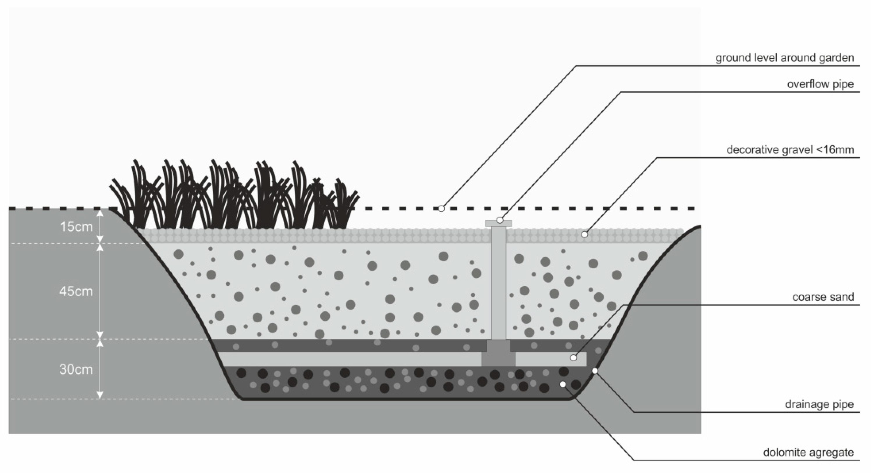
The installation of the garden started with the excavation of a trench with a depth of about 1 m, with a bottom filled with two 10 cm layer of gravel aggregates (8–16 mm and 2–8 mm size) over which a perforated drainage pipe (diameter 90 mm), enveloped in coconut braid cloth, was laid. A vertical overflow pipe (also 90 mm in diameter) installed into the drainage pipe and protruding about 10 cm over the decorative surface gravel of the garden, allows rapid infiltration in case of high intensity events. The horizontal drainage pipe is covered by a 30 cm layer of fine gravel aggregate. The space between the drainage layer and the surface (45 cm) is filled with a mix of coarse sand, brick ore and dolomite aggregate. (
Figure 6). The drainage pipe is connected to the public storm water drainage system to avoid overflow and local flooding in case of extreme events. The rain garden top layer consists of a 15–20 cm thick decorative gravel and stonecrop (
Sedum spp.) vegetation, with a 2% slope from sides to center. Stonecrop is a succulent perennial plant ideal for dry areas, with easy maintenance and low culture requirements. The chosen plants are Jade and Echeveria.
Runoff volumes were calculated (using the same rainfall data of case 1) as: runoff from parking, 226 m3/year, and from roof, 1047 m3/year; the average volume of rainwater overflow to the sewage system after rain garden implementation was estimated at less than 10 m3/yr. In this case, parking area runoff, representing a small fraction of overall runoff, was discharged directly to the storm sewer, at a cost estimated at 90 €/year.
Before construction of the raingarden, the cost of stormwater discharge into the sewer involved payment of a fee of 220 €/year. The rain garden construction cost was quite low (12.3 €/m
2, excluding vegetation), and on the grounds of analyses carried out during the first year of operation, annual maintenance and operating costs were estimated at about 0.5 €/m
2/year. The economic summary of the solution is presented in
Table 4.
Figures in
Table 4 are based on “design” rainfall volumes and actual billings received. With the same assumptions adopted in case 1, it can be seen that the entire investment for raingarden installation was recovered in less than one year. Assuming a useful project life of 8–10 years (after which some intervention to restore soil permeability would probably be necessary) accrued tariff savings between 2900 and 4100 € would have accumulated, or between 13 and 18 times the initial cost for raingarden operation.


