A New Spiral Potato Cleaner to Enhance the Removal of Impurities and Soil Clods in Potato Harvesting


 ,
, 
Abstract
:1. Introduction
2. Materials and Methods
2.1. New Spiral Potato Cleaner Developed
2.2. Theoretical Study
- −
- is the force of the weight of body M of variable mass. This force is applied in the center of the mass of the body studied, directed vertically downward and numerically equal to:where:
- −
- g is the acceleration of gravity;
- −
- are the normal reactions of the adjacent helices of the spiral, at the contact points K1 and K2, respectively. They are directed, respectively, at angles ψ1 and ψ2 to axis Oz and are located in a plane, parallel to plane zOy;
- −
- are the forces of friction. These forces are directed along the tangents to the surface of the spiral helices, applied, respectively, at points K1 and K2 of contact to the side, opposite to the relative speed of the motion of body M and, as is known, will numerically equal:where:
- −
- is the coefficient of friction of body M sliding along the surface of the spiral helices and Ni is the normal reaction of the helices of the working surface of the spiral;
- −
- is the force from the acceleration of the oscillating motion of the cleaning spiral, arising due to the presence of deflection of the longitudinal axis of the spiral under the action of the weight of the entire potato heap, entering on the cleaning surface.
- −
- A is the amplitude of oscillations and is the angular velocity of rotation of the spiral.
- −
- is the mass of a material point (in this case, the mass of body M);
- −
- is the velocity of a material point;
- −
- is the geometric sum of external forces that act upon a material point (conditionally, upon a material body M) at an arbitrary moment of time t.
2.3. Experimental Test
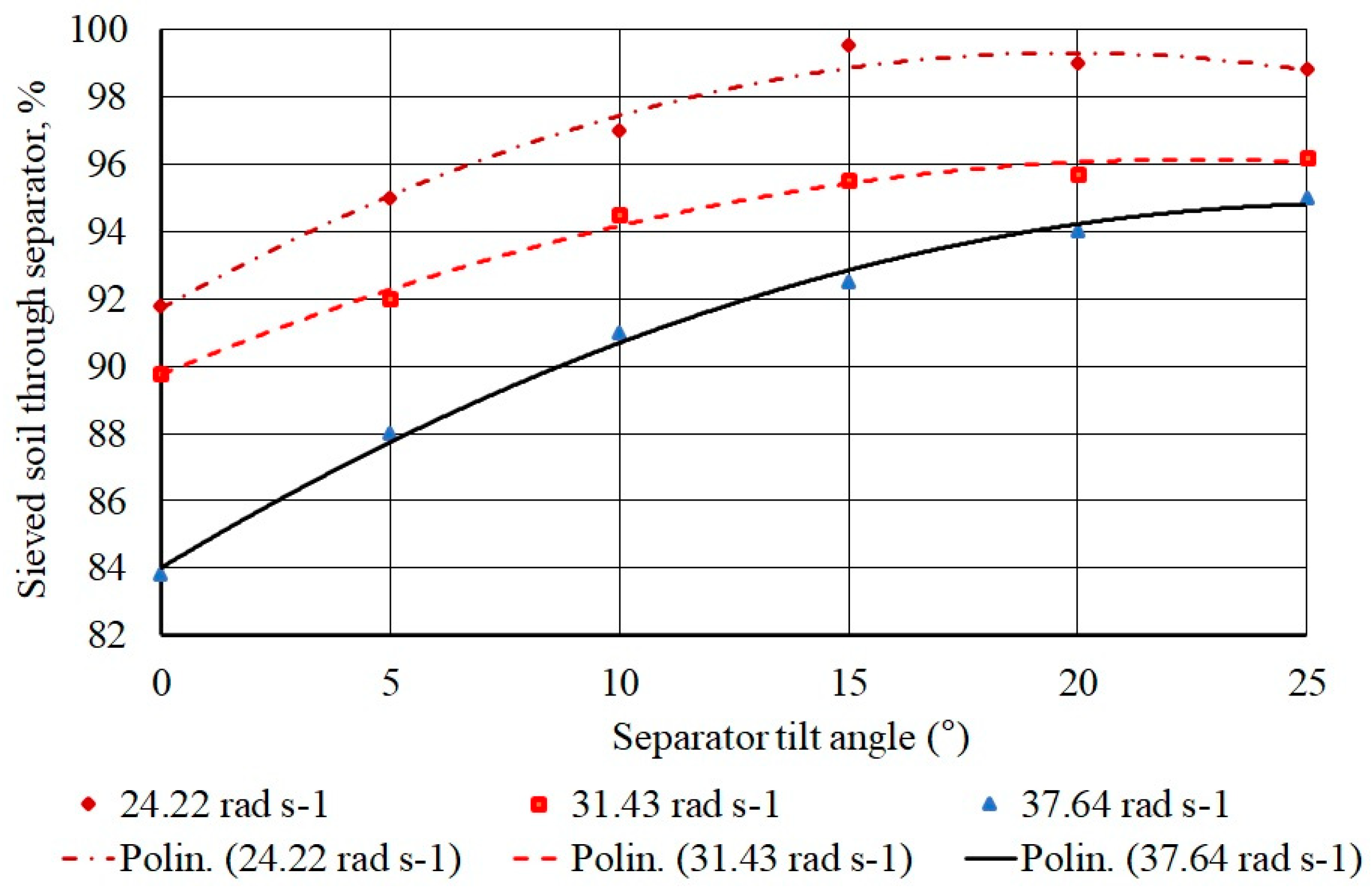
- the screening ability of the cleaner :
- the intensity separation of admixtures , kg s−1:whereis the separation time, s.
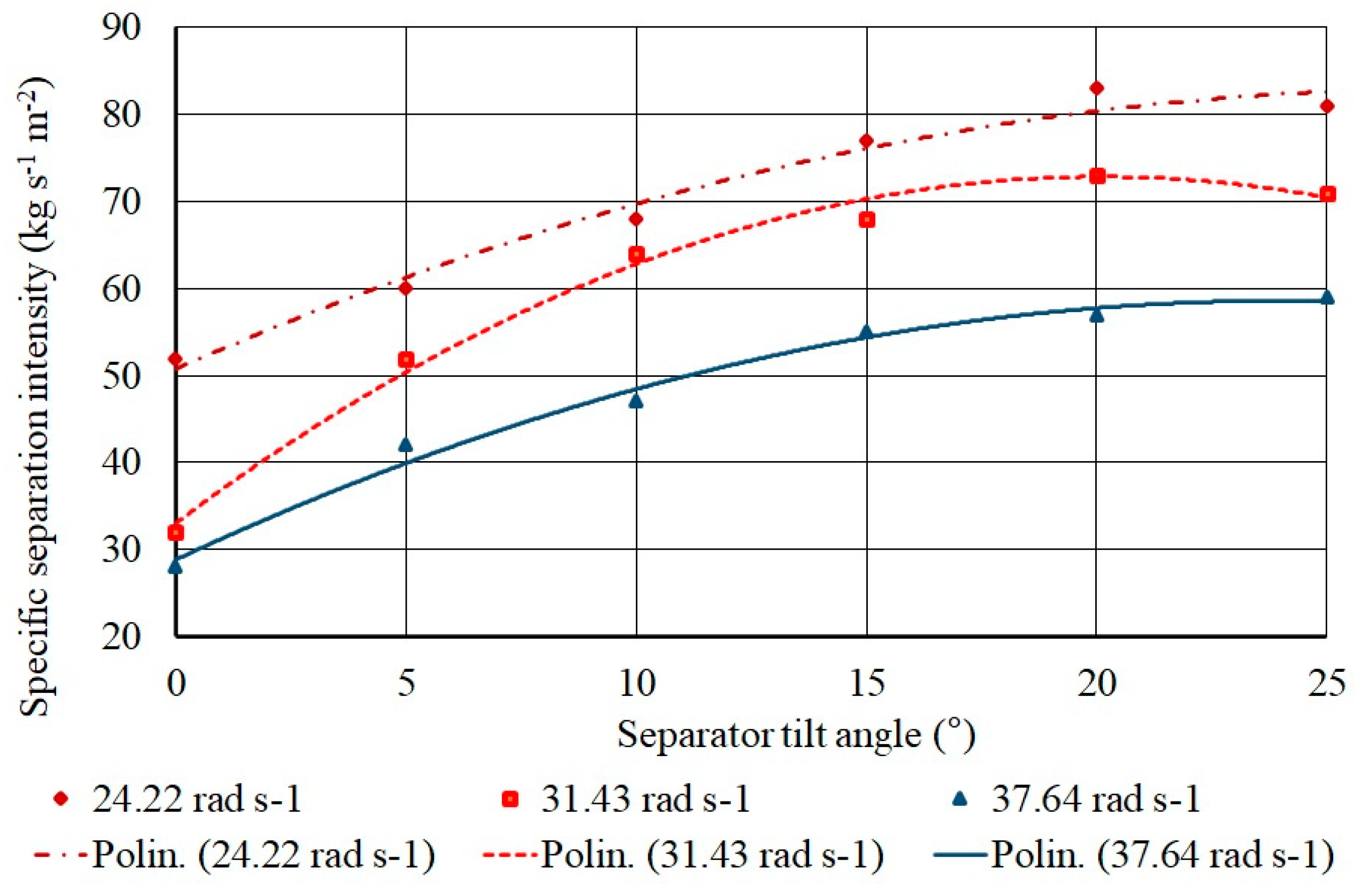
- the specific separation intensity , kg s−1 m−2:whereS is the area of the separation surface, .
2.4. Data Analysis
3. Results and Discussion
3.1. Numerical Results
3.2. Experimental Results
4. Conclusions
Author Contributions
Funding
Conflicts of Interest
Appendix A
References
- Mensah, J. Sustainable development: Meaning, history, principles, pillars, and implications for human action: Literature review. Cogent Soc. Sci. 2019, 5, 1653531. [Google Scholar] [CrossRef]
- Hou, D.; Bolan, N.S.; Tsang, D.C.; Kirkham, M.B.; O’Connor, D. Sustainable soil use and management: An interdisciplinary and systematic approach. Sci. Total. Environ. 2020, 729, 138961. [Google Scholar] [CrossRef] [PubMed]
- Sawicka, B.; Hameed, T.S. Farmers’ knowledge of sustainable potato cultivation techniques in Poland. Agron. Sci. 2019, 74, 81–98. [Google Scholar] [CrossRef]
- Esehaghbeygi, A.; Besharati, S. Potato variety and storage for tuber sensitivity in bruising. World Appl. Sci. J. 2009, 7, 1504–1507. [Google Scholar]
- Bulgakov, V.; Pascuzzi, S.; Anifantis, A.S.; Santoro, F. Oscillations analysis of front-mounted beet topper machine for biomass harvesting. Energies 2019, 12, 2774. [Google Scholar] [CrossRef] [Green Version]
- Scott, G.J. Maps, models, and muddles: World trends and patterns in potatoes revisited. Potato Res. 2002, 45, 45–77. [Google Scholar] [CrossRef]
- Keijbets, M.J.H. Potato processing for the consumer: Developments and future challenges. Potato Res. 2008, 51, 271–281. [Google Scholar] [CrossRef]
- Polacchi, W.; Weisell, R.; Marroni, S.; Mazar, I. Derivation of nutrient values for FAO statistical databases. J. Food Compos. Anal. 2002, 15, 515–522. [Google Scholar] [CrossRef]
- Adamchuk, V.; Prysyazhnyi, V.; Ivanovs, S.; Bulgakov, V. Investigations in technological method of growing potatoes under mulch of straw and its effect on the yield. In Proceedings of the 15th International Scientific Conference Engineering for Rural Development, Jelgava, Latvia, 25–27 May 2016; pp. 1098–1103. [Google Scholar]
- Bentini, M.; Caprara, C.; Martelli, R. Harvesting damage to potato tubers by analysis of impacts recorded with an instrumented sphere. Biosyst. Eng. 2006, 94, 75–85. [Google Scholar] [CrossRef]
- Al-Mallahi, A.; Kataoka, T.; Okamoto, H.; Shibata, Y. Detection of potato tubers using an ultraviolet imaging-based machine vision system. Biosyst. Eng. 2010, 105, 257–265. [Google Scholar] [CrossRef]
- Ichiki, H.; Nguyen Van, N.; Yoshinaga, K. Stone-cold separation and its application to potato cultivation in Hokkaido; Bio-oriented Technology Research Advancement Institution: 2013. Eng. Agric. Environ. Food 2013, 6, 77–85. [Google Scholar]
- Guerrieri, A.S.; Anifantis, A.S.; Santoro, F.; Pascuzzi, S. Study of a large square baler with innovative technological systems that optimize the baling effectiveness. Agriculture 2019, 9, 86. [Google Scholar] [CrossRef] [Green Version]
- Bulgakov, V.; Ivanovs, S.; Adamchuk, V.; Ihnatiev, Y. Investigation of the influence of the parameters of the experimental spiral potato heap separator on the quality of work. Agron. Res. 2017, 15, 044–054. [Google Scholar]
- Bulgakov, V.; Pascuzzi, S.; Nikolaenko, S.; Santoro, F.; Anifantis, A.S.; Olt, J. Theoretical study on sieving of potato heap elements in spiral separator. Agron. Res. 2019, 17, 33–48. [Google Scholar]
- Pascuzzi, S.; Santoro, F. Evaluation of farmers’ OSH hazard in operationnearby mobile telephone radio base stations. Eng. Rural Dev. 2017, 16, 748–755. [Google Scholar] [CrossRef]
- Santoro, F.; Anifantis, A.S.; Ruggiero, G.; Zavadskiy, V.; Pascuzzi, S. Lightning protection systems suitable for stables: A case study. Agriculture 2019, 9, 72. [Google Scholar] [CrossRef] [Green Version]
- Pascuzzi, S.; Santoro, F. Analysis of the almond harvesting and hulling mechanization process: A case study. Agriculture 2017, 7, 100. [Google Scholar] [CrossRef] [Green Version]
- Cerruto, E.; Giuseppe, M.; Santoro, F.; Pascuzzi, S. Operator dermal exposure to pesticides in tomato and strawberry greenhouses from hand-held sprayers. Sustainability 2018, 10, 2273. [Google Scholar] [CrossRef] [Green Version]
- Pascuzzi, S.; Blanco, I.; Anifantis, A.S.; Scarascia Mugnozza, G. Hazards assessment and technical actions due to the production of pressured hydrogen within a pilot photovoltaic-electrolyzer-fuel cell power system for agricultural equipment. J. Agric. Eng. 2016, 47, 89–93. [Google Scholar]
- Pascuzzi, S.; Cerruto, E. An innovative pneumatic electrostatic sprayer useful for tendone vineyards. J. Agric. Eng. 2015, 46, 123–127. [Google Scholar] [CrossRef] [Green Version]
- Vasilenko, P.M. Introduction to Agricultural Mechanics; Selhoz Obrazovanie: Kiev, Ukraine, 1996; p. 234. (In Ukrainian) [Google Scholar]
- Bulgakov, V.; Holovach, I.; Ruzhylo, Z.; Pascuzzi, S.; Santoro, F.; Anifantis, A.S. Cleaner of a Heap of Root Crops from Impuritie. Patent UA 120234 A 01 D 33/08, B 08 B 7/04, 25 October 2017. [Google Scholar]
- Bulgakov, V.; Pascuzzi, S.; Adamchuk, V.; Ivanovs, S.; Pylypaka, S. A theoretical study of the limit path of the movement of a layer of soil along the plough mouldboard. Soil Tillage Res. 2019, 195, 104406. [Google Scholar] [CrossRef]
- Bulgakov, V.; Pascuzzi, S.; Adamchuk, V.; Kuvachov, V.; Nozdrovický, L. Theoretical study of transverse offsets of wide span tractor working implements and their influence on damage to row crops. Agriculture 2019, 9, 144. [Google Scholar] [CrossRef] [Green Version]
- Bulgakov, V.; Pascuzzi, S.; Ivanovs, S.; Kaletnik, G.; Yanovich, V. Angular oscillation model to predict the performance of a vibratory ball mill for the fine grinding of grain. Biosyst. Eng. 2018, 171, 155–164. [Google Scholar] [CrossRef]
- Bulgakov, V.; Pascuzzi, S.; Nadykto, V.; Ivanovs, S. A Mathematical model of the plane-parallel movement of an asymmetric machine-and-tractor aggregate. Agriculture 2018, 8, 151. [Google Scholar] [CrossRef] [Green Version]
- Bulgakov, V.; Pascuzzi, S.; Ivanovs, S.; Nadykto, V.; Nowak, J. Kinematic discrepancy between driving wheels evaluated for a modular traction device. Biosyst. Eng. 2020, 196, 88–96. [Google Scholar] [CrossRef]
- Bulgakov, V.; Pascuzzi, S.; Santoro, F.; Anifantis, A.S. Mathematical model of the plane-parallel movement of the self-propelled root-harvesting machine. Sustainability 2018, 10, 3614. [Google Scholar] [CrossRef] [Green Version]
- Greenspan, D.; Carnahan, B.; Luther, H.A.; Wilkes, J.O. Applied numerical methods. Math. Comput. 1970, 24, 750. [Google Scholar] [CrossRef]
- Bulgakov, V.; Pascuzzi, S.; Ivanovs, S.; Santoro, F.; Anifantis, A.S.; Ihnatiev, I. Performance assessment of front-mounted beet topper machine for biomass harvesting. Energies 2020, 13, 3524. [Google Scholar] [CrossRef]
- Mitrofanov, V.S. Physico-mechanical properties of potatoes. In Theory, Design and Production of Agricultural Machinery; Mechanical Engineering: Moscow, Russia, 1997; Volume 5, p. 511. (In Russian) [Google Scholar]
- Petrov, G.D. Potato Harvesting Machines; Mechanical Engineering: Moscow, Russia, 2004; p. 320. (In Russian) [Google Scholar]
- Birch, P.R.J.; Bryan, G.J.; Fenton, B.; Gilroy, E.M.; Hein, I.; Jones, J.T.; Prashar, A.; Taylor, M.A.; Torrance, L.; Toth, I.K. Crops that feed the world 8: Potato: Are the trends of increased global production sustainable? Food Secur. 2012, 4, 477–508. [Google Scholar] [CrossRef]


| Indicator | Unit of Measurement | Value |
|---|---|---|
| Length of the cleaner | m | 0.40 |
| Width of the cleaner | m | 0.55 |
| Number of the cleaning spirals | pieces | 3 |
| Inter-helix gaps | m | 0.031 |
| External diameter of the spirals | m | 0.133 |
| Total area of the cleaner | m2 | 0.27 |
| Area of the “effective section” of the cleaner | m2 | 0.20 |
| Inclination | Polynomial Regression | R2 | e |
|---|---|---|---|
| α = 0° | ΔM = −0.0007 ω 2 + 0.0258 ω + 0.0693 | 0.9951 | −8.44 × 10⁻⁵ |
| α = 10° | ΔM = −0.0006 ω 2 + 0.0197 ω + 0.3473 | 0.9964 | +4.32 × 10⁴ |
| α = 20° | ΔM = −0.0002 ω 2 + 0.0013 ω + 0.6085 | 0.9961 | −1.23 × 10⁴ |
| Angular Speed (rad s−1) | Polynomial Regression | R2 | e |
|---|---|---|---|
| ω = 24.22 | μ = −0.0193α 2 + 0.765α + 91.707 | 0.9839 | +0.0033 |
| ω = 31.43 | μ = −0.0126α 2 + 0.5681α + 89.746 | 0.9893 | −0.0101 |
| ω = 37.64 | μ = −0.0157α 2 + 0.8243α + 84.014 | 0.9953 | −0.0035 |
| Angular Speed (rad s−1) | Polynomial Regression | R2 | e |
|---|---|---|---|
| ω = 24.22 | qn = 0.0414α2 + 2.31α + 50.786 | 0.9787 | −0.0065 |
| ω = 31.43 | qn = −0.0986α 2 + 3.9614α + 33.071 | 0.9913 | +0.0069 |
| ω = 37.64 | qn = −0.0514α 2 + 2.4743α + 28.857 | 0.9880 | −0.0067 |
Publisher’s Note: MDPI stays neutral with regard to jurisdictional claims in published maps and institutional affiliations. |
© 2020 by the authors. Licensee MDPI, Basel, Switzerland. This article is an open access article distributed under the terms and conditions of the Creative Commons Attribution (CC BY) license (http://creativecommons.org/licenses/by/4.0/).
Share and Cite
Bulgakov, V.; Pascuzzi, S.; Ivanovs, S.; Ruzhylo, Z.; Fedosiy, I.; Santoro, F. A New Spiral Potato Cleaner to Enhance the Removal of Impurities and Soil Clods in Potato Harvesting. Sustainability 2020, 12, 9788. https://doi.org/10.3390/su12239788
Bulgakov V, Pascuzzi S, Ivanovs S, Ruzhylo Z, Fedosiy I, Santoro F. A New Spiral Potato Cleaner to Enhance the Removal of Impurities and Soil Clods in Potato Harvesting. Sustainability. 2020; 12(23):9788. https://doi.org/10.3390/su12239788
Chicago/Turabian StyleBulgakov, Volodymyr, Simone Pascuzzi, Semjons Ivanovs, Zinoviy Ruzhylo, Ivan Fedosiy, and Francesco Santoro. 2020. "A New Spiral Potato Cleaner to Enhance the Removal of Impurities and Soil Clods in Potato Harvesting" Sustainability 12, no. 23: 9788. https://doi.org/10.3390/su12239788