Article

Sustainability of Vibration Mitigation Methods Using Meta-Materials/Structures along Railway Corridors Exposed to Adverse Weather Conditions

Department of Civil Engineering, School of Engineering, The University of Birmingham, Birmingham B15 2TT, UK
*
Author to whom correspondence should be addressed.
Sustainability 2020, 12(24), 10236; https://doi.org/10.3390/su122410236
Submission received: 17 November 2020 / Revised: 1 December 2020 / Accepted: 4 December 2020 / Published: 8 December 2020
(This article belongs to the Section Sustainable Materials)

Abstract

:
Noises and vibrations caused by operating transport systems can seriously affect people’s health and environmental ecosystems. Railway-induced vibrations in urban settings can cause disturbances and damages to surrounding buildings, infrastructures and residents. Over many decades, a number of mitigation methods have been proposed to attenuate vibrations at the source, in the transmission path, or at the receiver. In fact, low-frequency or ground-borne vibration is turned out to be more difficult to be mitigated at source, whilst some attenuation measures in propagation path can be applicable. To broaden the mitigating range at the low-frequency band, the applications of meta-materials/structures have been established. In railway systems, periodic structures or resonators can be installed near the protected buildings to isolate the vibrations. Despite a large number of proposed attenuation methods, the sustainability of those methods has not been determined. Based on rational engineering assumptions, the discounted cash flows in construction and maintenance processes are analysed in this study to evaluate lifecycle costs and the quantity of materials and fuels, as well as the amount of carbon emissions. This study is the world’s first to identify the efficacy and sustainability of some transmission path attenuation methods in both normal and adverse weather conditions. It reveals that geofoam trenches and wave impeding blocks are the most suitable methods. Although metamaterial applications can significantly mitigate a wider range of lower frequency vibrations, the total cost and carbon emissions are relatively high. It is necessary to significantly modify design parameters in order to enable low-cost and low-carbon meta-materials/structures in reality.

1. Introduction

Railway systems have been regarded as one of the most sustainable and safest public transport modes. Since railway systems have expanded rapidly in many countries, some railway lines have been built in urban areas and surrounded by buildings and infrastructures. The disturbances caused by railway vibrations to the surrounding residents and buildings have raised special public attention. Railway vibrations can affect passenger ride comfort, and low-frequency vibrations can cause structural damages to the buildings, tunnels, and buried infrastructures near the railway lines [1]. To attenuate ground vibrations along railway corridors, some mitigation methods have been proposed and implemented in the industry. However, it is difficult to identify and select an optimal method in real-life practical situations due to the lack of detailed assessments about cost efficiency, sustainable values, and environmental impacts throughout their lifecycle [2].
To compare the effectiveness and sustainability of the mitigation methods in terms of lifecycle cost and carbon emissions, the sources of railway vibration and the types of attenuation methods need to be identified first. The railway vibration is mostly generated at the wheel-rail contact surface and transmited from the track to subgrade, formation and bedrock. The dynamic loads from the rolling stock cause the waves to propagate into the ground, especially when the wheel-rail interface is irregular or when significant defects exist. When the railway vibration penetrates through the ground and causes secondary vibration generation (e.g., through ground amplifcation, from tunneling pipes, etc.), this vibration effect is often referred to as ground-borne vibration [3,4]. The amplitude and frequency of railway vibrations mainly depend on the condition of trains and tracks and the ability of the soil layers to transmit and absorb dynamic impacts. Based on dynamic amplification factors, geological condition, and the mitigating locations, the attenuation methods can be classified into three categories, including: (i) mitigating vibrations at the source, (ii) attenuating vibration intensity in the propagation path, and (iii) isolating the receiver such as surrounding structures from vibrations [5,6]. Compared with the other two types of mitigation methods (i.e., methods (i) and (ii)), it is rather difficult and often cost-consuming to build a vibration isolation system or to change the foundation condition under the existing buildings or infrastructures [7,8,9,10]. Therefore, the vibration mitigations at the source or at the transmission path are preferable to be applied in practice. In this study, some common mitigation methods are discussed, including trenches, sheet pile wall and subgrade stiffening methods.
Although many methods for vibration mitigation at source or propagation path have been tested and applied, lesser scale of research with respect to metamaterials applications in vibration abatements have been conducted [11,12,13]. Metamaterials are artificially constructed materials, which have repeated patterns in the configuration. One of the critical features of metamaterials is that the wave with specific frequencies can be prevented from propagating through metamaterials because of the periodic arrangement [14]. Actually, in a seismic design, metamaterials have been verified in a numerical model for protecting the buildings from structural damage in the earthquake due to this wave attenuation feature [15]. Considering the vibration mitigation mechanism is similar to seismic protection, the application of seismic metamaterials in railway systems can be proposed and analyzed. Two types of novel mitigation methods are discussed in this project, including clamped metamaterial stopbands and metamaterial resonators.
To enhance a detailed evaluation of cost efficiency and environmental impacts, it is necessary to carry out a lifecycle assessment of the above abatement methods in comparison with some existing approaches (such as geofoam, steel sheet piles, jet grouting columns, and stone columns). This study unprecedentedly conducts the lifecycle assessment of vibration abatement methods in both usual and adverse conditions. A tangent railway section of 100 m in length has been selected for comparative analyses in this study. In the lifecycle cost analysis, the net present costs in the processes of construction, maintenance and renewal for each method are determined after analysing the cash flow in the 50-year period. Allowing for the time value of money, the discount rate is applied in the cost estimation. For the environmental impacts analysis, the total carbon footprint, including the embedded emissions of the required quantity of materials and the emissions from devices used in the installation and maintenance period is estimated. This paper highlights two novel vibration attenuation measures with respect to metamaterials applications and then compares with conventional abatement methods proposed in the previous studies. The lifecycle cost and carbon emissions of each method are later determined to justify sustainable development criteria. These two aspects are the highlight of this study as they underpin the pillars of sustainable development [16,17]. Based on the lifecycle assessment results, the effectiveness of these methods can be compared in terms of economy and environmental protection in both normal and adverse weather conditions. This investigation is the world’s first to determine the sustainability of the vibration abatement methods when exposed to extreme weather conditions. The insight into lifecycle cost and carbon footprint will underpin the sustainable strategies and cleaner solutions for railway noise and vibration mitigation practices when exposed to extreme events due to climate change uncertainties and natural hazards.

2. Methods for Vibration Mitigations in Railway Corridors

Since railway lines are usually constructed to connect communities, cities and urban areas, rail neighborhoods have often experienced a variety of vibro-acoustic nuisances. As such, a number of vibration mitigation measures have been studied by many preeimnent scholars in relevant research fields. Suitability assessments of vibration mitigation methods are often needed when planning new railway lines or when new buildings are to be built close to railway lines. However, every technique and method for vibration mitigation and abatement requires supporting infrastructures and makes use of engineering assumptions; even though various uncertainties are often taken into account in the mitigation design. There are two groups of train-induced ground-borne vibration: (i) low-frequency vibration (2–80 Hz) is a kind of feelable vibration in which its waves have longer wavelengths and deeper penetration under the ground; and (ii) higher frequency vibration (30–250 Hz) can cause minor vibration of walls and floors and radiate ground-borne noise [3]. In this study, the track and soil conditions for suitability evaluation of each mitigation method are set identical. Compared with the mitigation methods for higher frequency vibrations, it is relatively more difficult to attenuate vibrations with a low frequency because of longer wavelengths, larger transmission depth, and greater ground conditions [18]. It is important to note that most previous studies of meta-structures/materials were aimed for seismic mitigation. In this study, the train-induced vibration is focused so the modifications of the meta-structures for railway applications have been engineered using similar track and foundation parameters (detailed in the Appendix A) on the basis of the guidelines and predictions from those previous studies [19]. Considering that conventional at-source attenuation methods can only mitigate the vibration in a limited range of frequency, some methods that can control low-frequency vibration in railway systems will also be discussed in the following section.

2.1. Seismic Metamaterial Applications

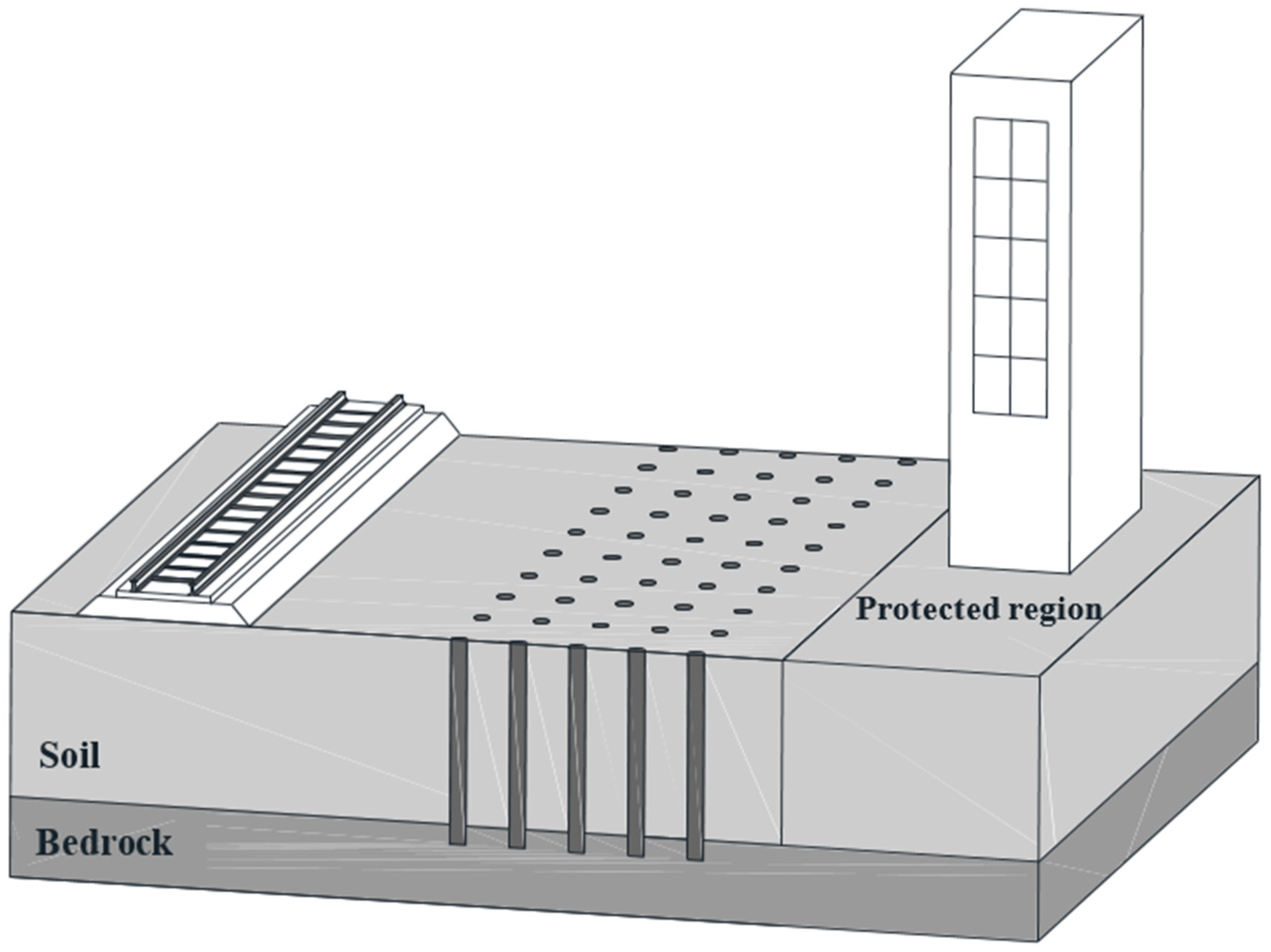
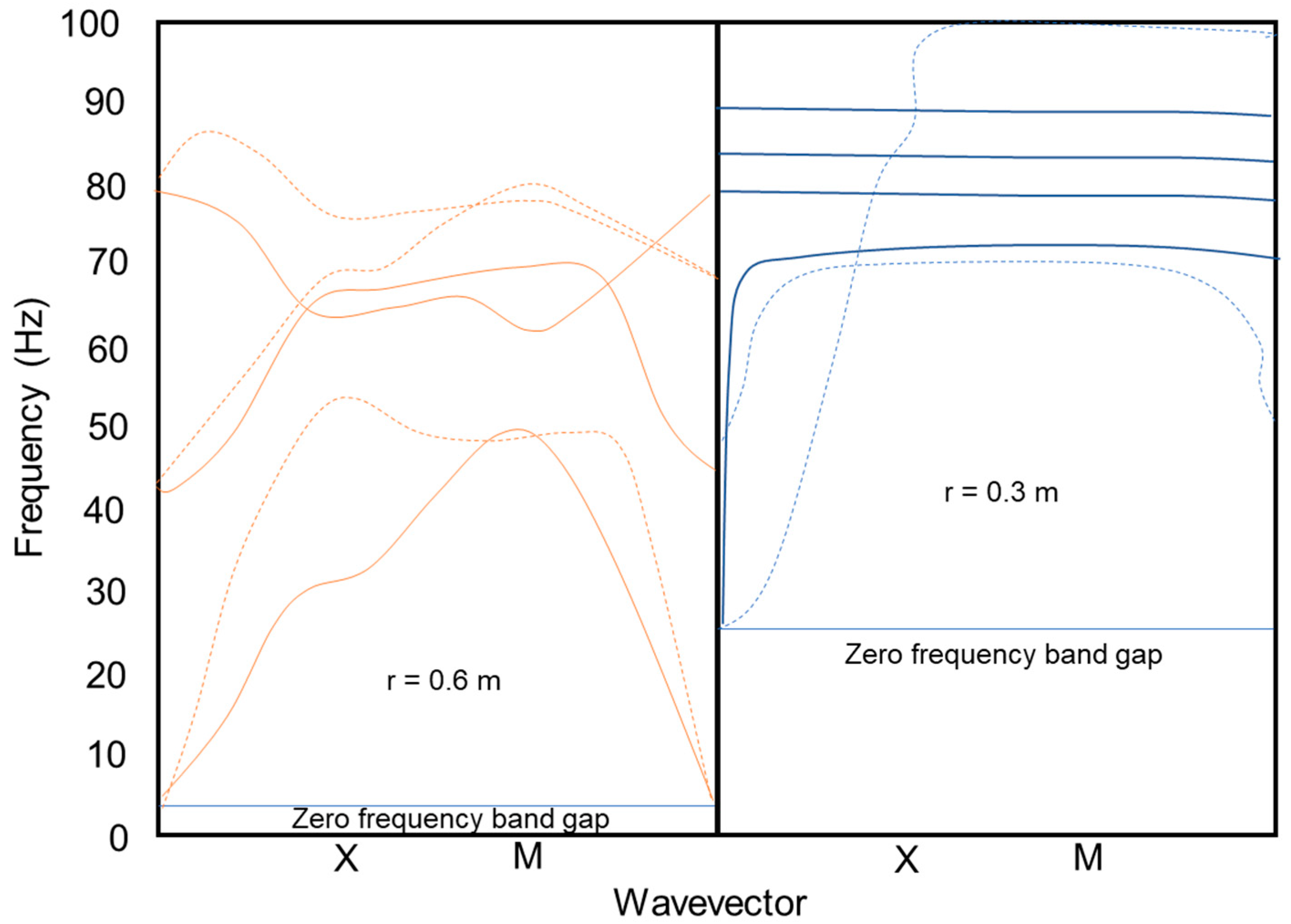
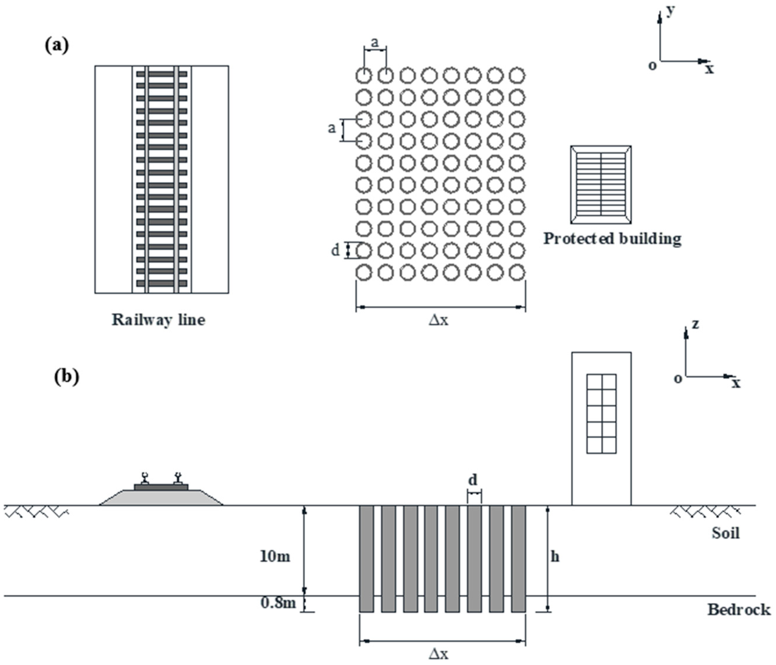
2.1.1. Clamped Metamaterial Stopbands

Based on previous studies, some researchers have proposed the application of periodic structure in the seismic protection of buildings. This idea came from the application of photonic crystals in light control technologies such as optical absorbers and invisibility cloaks. Photonic crystal is the periodic media, which have certain band-gaps so the optical waves in particular frequency ranges can be prevented from propagating through it. The band-gaps are actually hindered frequency ranges and would be formed if the wavelengths are much larger than the dimensions of structural elements forming the photonic crystal [20,21]. Given that seismic waves and optical waves have similar physical characteristics, band-gaps in periodic structures applied to suppress the light transmission can also be used to attenuate seismic waves.
Based on this theory, a clamped metamaterial stopband has been proposed to isolate buildings from seismic waves. This type of metamaterial is comprised of arrays of round columns clamped to the bedrock and aimed to form a zero-frequency stopband, which can hinder wave propagation [22]. For the application to seismic prevention, a protected building can be isolated from seismic waves by burying rows of columns in the bedrock around the building. Analogously, the clamped metamaterial can be utilized in railway systems to mitigate ground-borne vibrations. The vibration can be isolated completely in a low-frequency range from 1 to 30 Hz [23,24]. As Figure 1 shows, arrays of columns can be buried in the bedrock between the track and the surrounding building. In this way, vibration can be attenuated along the transmission path.
The proposal of this clamped metamaterial is inspired by the clamped structured thin plate model in Kirchhoff–Love theory, which indicates that the range of zero-frequency stopband is affected by the plate thickness. Then, the large disparity between wavelengths and plate thickness can broaden the band-gaps [25]. Similarly, the role of the buried depth of columns in the bedrock is equivalent to the plate thickness. Apart from the buried depth, the stopband range is also related to the column radius. The research conducted by Achaoui et al. [22] has compared the stopband range of clamped steel columns in different radii and found that clamped metamaterials with smaller radius columns would have wider stopbands. The dispersion curves of two different radii clamped columns buried in the 15 m soil layer and 0.8 m bedrock are illustrated in Figure 2. The range of zero-frequency stopband of clamped columns with radius 0.3 m is around 0–26 Hz, while radius 0.6 m columns have the stopband range approximately 0–4.5 Hz. Thus, buried depth and columns radius need to be considered in the design of clamped structure to achieve broader band-gaps.
Actually, traditional periodic structures such as pile barriers have been applied in civil engineering to mitigate ground vibration before the proposal of the clamped metamaterial. As Huang and Shi [26] indicated, the stopbands produced in pile barriers are always in high-frequency range because it is affected by spatial configuration and pile diameter. To attenuate low-frequency vibrations, larger diameter piles need to be utilized. This measure is not preferable if the space between the railway line and surrounding buildings is limited. Besides, too large diameter of piles would increase the difficulty in construction and maintenance.

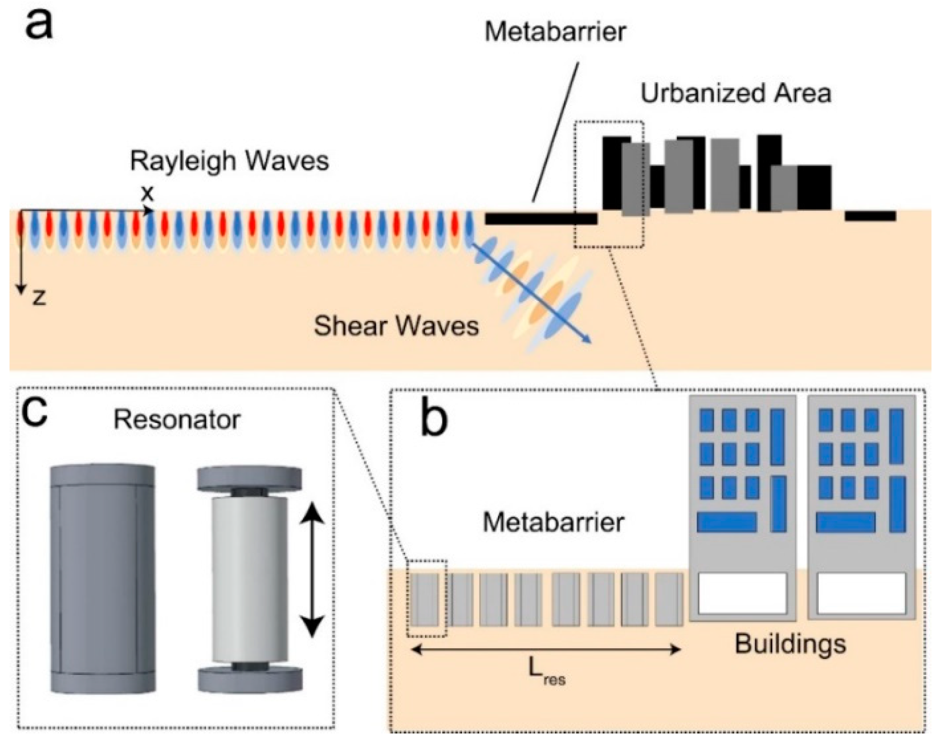
2.1.2. Metamaterial Resonators

Metamaterial resonators can be applied to attenuate the vibration by dissipating vibration energy in the process of local resonances before the waves arrive at the building. Resonators are commonly buried in the soil around the protected region and tuned to a particular frequency in accordance with the eigenfrequencies of the buildings. In this way, local resonances could be excited in the resonators when the frequency of propagating waves reaches the eigenfrequencies. The disturbance to the buildings caused by ground vibrations would be decreased due to local resonances [27]. Given that the mitigation mechanism of metamaterial resonators is not based on structural periodicity, the structural size of resonators would not be as large as the pile diameter in pile barriers discussed above in order to achieve low-frequency vibration abatements. This method could thus be more practical in construction. However, the complexity of metamaterial resonators components needs to be considered before employing this method. In general, this method can be designed to isolate vibrations in a low-frequency range of less than 10 Hz [19].
According to the wave attenuation mechanism of locally resonant metamaterials, the seismic metabarrier comprised of rows of cylinders with suspended inner resonator mass has been proposed by Palermo et al. [28]. This inner resonator is suspended by two elastic rubber bearings located at both ends of the outer hollow cylinder. In this buried resonant structure, the resonant frequency of the inner suspended mass is the key factor, which affects the band-gaps range. The structure and components of metabarrier are indicated in Figure 3. The local resonances can occur when the frequency of propagated elastic waves reaches the eigenfrequency of inner mass. Rayleigh waves can be converted into shear waves in this process and redirected into deeper soil to achieve the mitigation. As Liu et al. [29] pointed out, band-gaps in metamaterials resonators are in limited range and can just include some frequency values around the resonant frequency. To broaden the band-gaps’ range, resonators with different eigenfrequencies can be gathered in order and overlapped local resonance mode would be performed [30]. For the inner suspended resonator, the eigenfrequency is related to resonator mass and geometry characteristics of the bearings, so these parameters can be changed to achieve wider band-gaps. In this regard, it is feasible to apply this seismic metabarrier for the railway vibration abatement since the configuration is not complex and the band-gaps broadening is achievable. Besides, Palermo et al. [28] have built the scaled experimental model and found that this metamaterials resonator can well mitigate the seismic waves in frequency range below 10 Hz. Considering it is difficult to abate low-frequency vibrations using traditional measures, this novel method provides an alternative, effective solution.
Apart from the suspended resonator, Kim and Das [31] proposed another metamaterial resonator system, which consists of several groups of hollow cylinders with side holes; these cylinders are combined and buried around the protected area. The shielding zone of seismic waves is formed because of the negative shear modulus of metamaterials in resonators, which results in the dissipation of the velocity and energy of the waves. Although the configuration of this resonator system is not complex, the spacing between two cylinders is short, which may influence stress distribution on the buried cylinder. Hence, this resonator structure is not generally recommended in practical applications.

2.2. Trenches and Sheet Pile Wall

2.2.1. Geofoam Filled Trenches

The application of trenches is one of the common measures to provide vibration scattering. The waves can be diffracted at the trench so that the vibration abatement can be achieved. The effectiveness of waves impediment at trenches is related to geometric parameters, distance between the trench and the protected building, and in-filled materials property. In a previous study, a numerical model using various influence factors have been built and analyzed by many researchers. As Adam and Estorff [32] proved and compared with broadening the trench width, it is more effective to improve the screening performance by increasing the depth of trenches. The waves isolation performance can be enhanced by excavating the trench in a shorter distance from protected region. Besides, Thompson et al. [33] found that low stiffness in-filled material is beneficial to vibration isolation. These findings can be applied in the design of trenches to improve the performance. However, increased depth would affect the stability of open trenches. For deeper trenches, a supporting structure or in-filled materials need to be applied. Mizutani et al. [34] conducted real experiments, which have shown that this method can suppress up to 35dB of ground vibrations (in a frequency range of 1 to 30 Hz).
Geofoam is a polymeric material, which contains air-filled spherical particles and it is also called expanded polystyrene (EPS). This material has numerous applications in geotechnical engineering due to techanical performances such as compressible inclusion, vibration damping and lightweight fill [35,36]. Although geofoam is the lightweight material, it has high strength-to-weight ratio. In this regard, it is recommended to apply geofoam as an in-filled material in deep trenches so that trenches could bear larger compressive stress from surrounding soil. To investigate the effectiveness of geofoam-filled trenches in vibration screening, Murillo et al. [37] proposed centrifuge modelling in which the railway vibration was simulated. The results illustrated that the trench depth is the main factor, which determines the screening effect and the increase of depth-to-wavelength ratio would accelerate the decrease of waves amplitude in geofoam trenches, which can be employed to improve the trench performance.

2.2.2. Sheet Pile Wall

Sheet pile walls can be applied as a stiff wave barrier to isolate vibrations. Compared to trenches, the lateral stability of this structure is better. According to Dijckmans et al. [18], the performance of the sheet pile walls depends on the depth, stiffness and elastic modulus contrast to the soil. The depth of the sheet pile needs to be sufficiently larger than the wavelength of incident waves so that vibration screening effect can be achieved. Besides, the sheet pile wall is equivalent to orthotropic plate. The bending stiffness in the horizontal direction is much larger than that in the vertical direction so the former would have larger effects on the isolation efficacy. Actually, the sheet pile wall can be employed as the supplementary measure to reduce vibration after applying at-source abatement methods. In this way, low-frequency vibrations can be further reduced. However, based on Dijckmans et al. [18], the vibration can be suppressed up to 12 dB in the frequency range between 30 to 40 Hz, and up to 5 dB in other frequency ranges lesser than 100 Hz.

2.3. Subgrade Stiffening

Subgrade stiffening is the method of improving the stiffness of the soil and subgrade under the track to achieve waves impediment. As Skipp [38] mentioned, the location of stiffened soil is always directly below the track or at certain depth under the ground and the depth of stiffened soil layer would influence the stiffening effects. Given that stiffening the soil close to the track might result in track uplifting, it is preferable to select the methods, which can stiffen soil at a certain depth below the track for subgrade stiffening of the existing railway. Some alternative techniques of subgrade stiffening have been proposed in the past research, including jet grouting, vibro-replacement, and wave impeding blocks. Coulier et al. [39] observed that the vibration suppression using this technique can be up to 6 dB along a traditional rail corridor (48 m away from a vibration source) in the frequency range between 30 and 40 Hz.

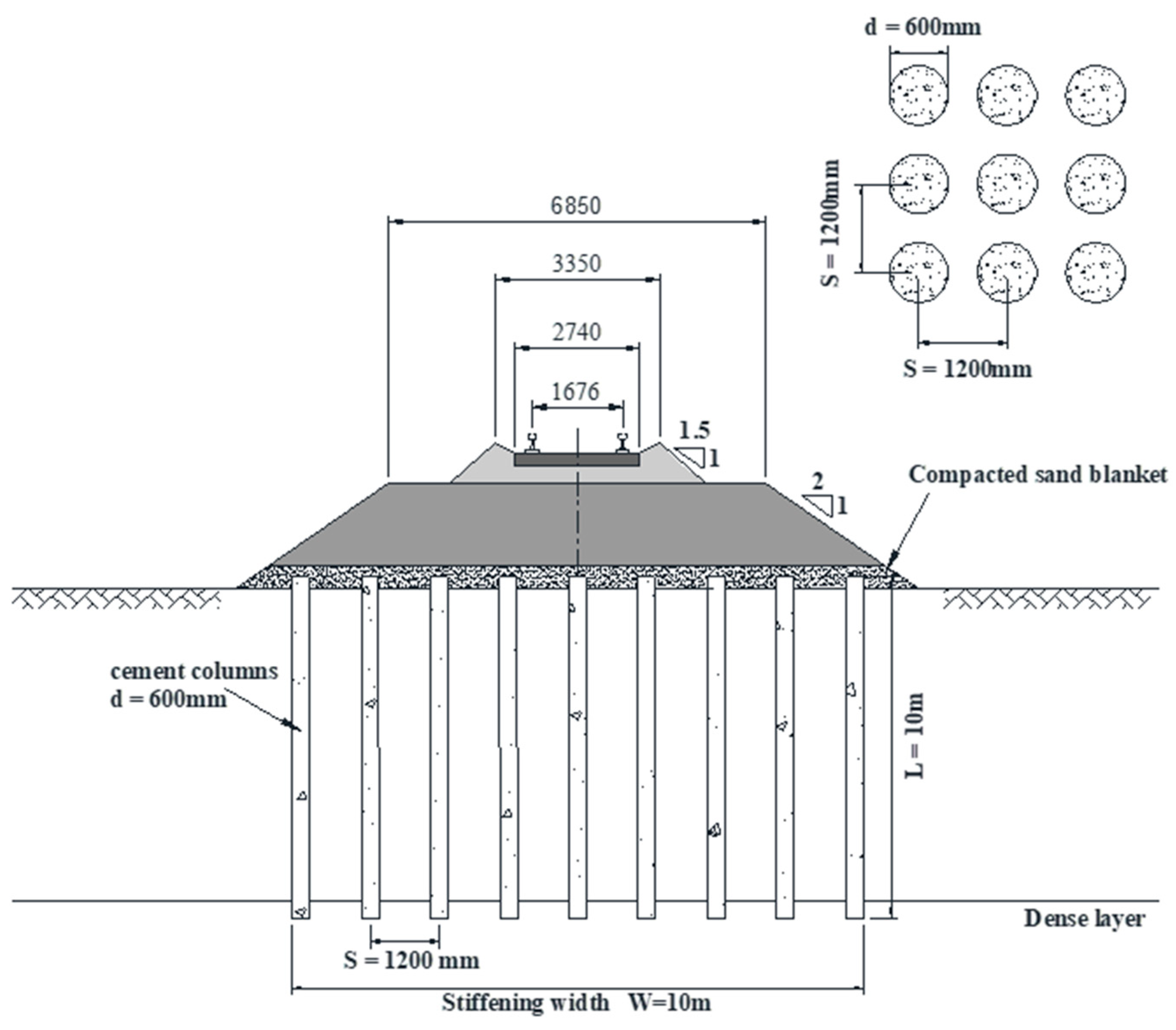
2.3.1. Jet Grouting Columns

Jet grouting is a mechanical method that can mix subgrade soil with the grout and form stiff mass underground. The high pressure of jet fluid can erode the soil and accelerate the mixture of soil particles and cement. This mixture would produce columns, which can decrease the permeability and compressibility of the original subgrade soil. Also, the stiffness of the subgrade would increase in this process, so differential settlement can be prevented and railway induced vibration would be mitigated [40,41]. The main jet fluid applied in this method is cement slurry. To form columns with different diameters and strengths that can be used in different soil conditions, air and water can also be introduced into the grout. As the types of jet fluid increase, the friction between the grout and soil at the nozzle would reduce. In this way, the grout stream would become more concentrated and the quality of the columns would be improved [42]. Considering the stiffening mechanism of jet grouting is based on grout erosion, this method can be employed in wider range of soil types from clays to gravels. However, it is notable that the jet pressure would be affected by treatment depth. This technique can reduce ground vibration up to 3 dB in a low-frequency range lesser than 10 Hz [19].

2.3.2. Vibro-Replacement with Stone Columns

Vibro-replacement is another subgrade stiffening method, which can densify the soil and replace soft soil with coarse material such as crushed stones or gravels. This replacement process is actually the installation process of stone columns in subsoil by a special depth vibrator [43]. The stone columns and the surrounding densified soil constitute an integrated support system with low compressibility and improved strength, so the subsoil would be stiffened. The stiffening effect of vibro-replacement is influenced less by the treatment depth, which is different from jet grouting. As Black et al. [44] pointed out, the vibratory compaction process may result in excessive settlement of the track. Thus, additional ballast materials may need to be prepared to level up the track before construction. The ground vibration can be suppressed using this method up to 3 dB in a low-frequency range lesser than 10 Hz [19].

2.3.3. Wave Impeding Blocks

Wave impending block (WIB) can also be utilized in vibration reduction by introducing the artificial stiffened inclusion at a certain depth in the subgrade. Compared to other subgrade stiffening methods, which stiffen the soil close to the track, WIB would cause smaller disturbance to the track. As Peplow et al. [45] indicated, the installation of WIB could change the cut-off frequency of the upper layer, so the waves below this frequency are stopped from propagating. This modified wave propagation regime results in the reduction of low-frequency vibration in the transmission path. Besides, Jiang et al. [46] found that WIB could achieve better performance in layered ground but the increased depth of stiffened block has little effect on the improvement of the performance, which should be considered in the design period. It was found that WIB can suppress the ground vibrations between 6 and 8 dB in a low-frequency range (<30 Hz) [47,48].

2.4. Impacts of Extreme Temperature

Climate change has always been a focus issue that is being investigated by many researchers. The influence of global warming on the operation and maintenance of infrastructures has been considered in the construction industry. As Binti et al. [49,50,51] mentioned, extreme weather would result in the increase of renewal cost and the acceleration of wear and degradation in railway components. Kim et al. [52] found that concrete would have lower later-age strength after curing in high temperature (40 °C). Given that most of the mitigation methods discussed in this project consist of concrete materials, the effects of extreme temperature on the lifespan and performance of each method need to be considered.

3. Methodology

Lifecycle assessment is a systematic method, which can evaluate the mitigation measures in the areas of economic effect and environmental impact. In this study, lifecycle cost and carbon emissions in different measures are calculated and compared. Considering the quantity of materials needed in each abatement method [53,54,55,56,57,58,59,60] is the main factor (which influences the overall cost and carbon footprint), rational engineering assumptions are made before conducting the lifecycle assessments.

3.1. Engineering Assumptions

The engineering assumptions provide the same baseline for estimating material demand, which would be consistent in different periods. The assumptions of the structure size and materials demand are based on previous literature and industry reports. The relevant parameters, which affect the efficacy of abatement methods, should be considered when selecting the size of vibration isolation structure. The materials quantities in a 100-metre railway line can be estimated and the assumptions in the control case of each method are identical as illustrated in the following.
(1)
Clamped metamaterial stopbands:
The number of cylinders in the periodic structure can be estimated according to the widths of the seismic barrier. As Kim [53] proposed, the width of the barrier can be calculated by Equation (1). Although this equation was initially based on a seismic waveform, Kim [53] and Achaoui et al. [22] found that it could also be used to estimate the size of meta-barriers for similar waveform vibrations, such as the train-induced ground-borne vibration. The uncertainty of soil conditions can be taken into account by the factor of safety in design process.
Δ x = ln 10 2 π λ Δ M n = 0.366 λ n Δ M
where λ is the wavelength of the incident wave, n is the refractive index of wave barrier and Δ M is the seismic magnitude of Richter scale needed to reduce, which is the expected reduction of seismic magnitude after the waves transmit through the protected zone. To apply seismic metamaterial in attenuating railway induced vibrations, it is assumed using simplication approaches in [22] that λ = 100 m and n = 1.5, then the width of metamaterial periodic structure Δ x = 25   m for Δ M = 1 . In this study, the steel pipes (diameter d = 1200 mm; thickness t = 30 mm; unit weight = 866 kg/m) are selected to form periodic structure [22]). The configuration of the pipes is shown in Figure 4. The length of the pipe is related to the soil layer thickness and buried depth in the bedrock. The reasonable pipe spacing is selected (a = 3600 mm) to avoid the effects of surrounding pipes in the groups. Thus, the total number pipes can be calculated based on the pipes diameter and the clamped structure width. The justifications and details of the pipes’ parameters and the quantities are shown in Appendix A.
(2)
Metamaterial resonators:
According to the scaled experimental setup related to metamaterial resonators [54], the parameters of each component can be estimated. Considering that the train-induced ground-borne vibration could be an elastic surface wave, the design by Krödel et al. [54] and Palermo et al. [28] can be modified for railway applications. Note that uncertainties in soil conditions are not within the scope of this study. As shown in Figure 5, each resonator consists of an outer concrete pipe (rc = 600 mm; thickness t = 30 mm; ρc = 2500 kg/m3; hc = 8 m); an inner suspended steel mass (rr = 225 mm; ρr = 7800 kg/m3; hr = 5 m) suspended by two rubber bearings or soft springs (ρeff = 1225 kg/m3; h = 1 m). Considering the broadening of band-gaps range does not depend on the periodic arrangement but the density of resonators arrangement. The triangular lattice is selected to achieve a high-density arrangement.
(3)
Geofoam filled trenches:
The geofoam density is around 1–2% to the soil and ranges from 10–30 kg/m3 [55]. In this study, the 16 kg/m3 geofoam is selected for the cost and carbon emission calculations. The trench depth is the main factor, which determines the efficacy of vibration scattering. Some design criterion indicated that the minimum depth should be 0.6 times Rayleigh wavelength to achieve an effective vibration isolation [33]. Based on parameters in previous research, a 6-m depth and 8-m width geofoam trench is analyzed.
(4)
Sheet pile wall:
Compared with the uniform depth wall, the alternating depth wall is more effective to scatter low-frequency vibration and costs less [18]. Thus, cost efficiency of the wall consisting of the 12 m depth sheet piles with every fourth pile alternating to 18 m depth is evaluated.
(5)
Jet grouting columns:
The stiffening width of jet grouting is related to the width of ballast and formation above the subgrade. The arrangement and design parameters of the cement columns are indicated in Figure 6; the total number of columns can be calculate based on the stiffening width, the diameter and the spacing of columns [56].
(6)
Vibro-replacement with stone columns:
The arrangement of stone columns is similar to jet grouting columns as shown in Figure 6. The design parameters (column diameter d = 1000 mm, spacing s = 2000 mm; stiffening width w = 10 m) are assumed based on the previous practical application [44]. Other details of the design parameters are illustrated in Appendix A.
(7)
Wave impeding blocks:
The inserted block (with a width of 6 m; thickness of 1 m; and depth of 1 m) has been adopted for analyses. The assumption is based on the previous parametric analysis [60], which compares the influence of depth, width, and depth on impeding effectiveness.

3.2. Lifecycle Cost Analysis

Lifecycle analysis can be applied to estimate the costs of vibration attenuation methods over the lifespan of the employed methods and materials. Considering the time value of money is changeable, the Net Present Value (NPV) of lifecycle cost is used to compare the cost efficiency of each vibration reduction method [61]. The cost and carbon footprint are key life cycle perspectives for a project’s decision making in compliance with ISO 14,040 [62]. In this study, the 50-year period lifecycle is selected for analysis and the base financial year is assumed to be 2018. The discount rate of 6% is adopted in accordance with the recommendation value for governmental projects [63]. The discounted cash flow, which includes initial cost, maintenance cost and renewal cost, are then analyzed. The initial costs of materials are illustrated in Table 1, which is estimated based on the costing and price data from industry reports and former research. The principles of assessment are based on ISO 14,040 [62]. In this study, the function of the meta-structures is to provide the abatement to railway ground vibrations stemming from the movements of trains. Its performance characteristics are based on the suppression (i.e., insertion losses) of groundborne vibrations. The overarching functional unit of the meta-structures and their components is to assure that insertion losses occur in a low-frequency range (0–40 Hz). The specific functional unit is set as the insertion loss more than 3–6 dB of ground-borne vibrations in an urban setting. This implies that the track corridor is the system boundary, which can be modified to assure the construction of each type of vibration abatement techniques.
As for maintenance costs, no direct maintenance cost is considered in the analysis because the vibration attenuation methods discussed above are all applied underground and can avoid large disturbance caused by the operation of railway. As Table 2 indicates, the maintenance cost (based on net present value, NPV at 6% expected rate of return) is estimated from the costs of rail and ballast maintenance [64].
The maintenance cost in high temperature and low temperature (exceeding the 95th percentile) is shown in Table 3. The lifespan of materials used in each method is assumed to be not affected by the extreme temperature. The maintenance interval is considered to be shorter because the infrastructure of vibration isolation is built using concrete, rubber and steel; the performance of some materials can be vulnerable to and influenced by extreme temperature. Also, more frequent inspection should be carried out in adverse situations.

3.3. Carbon Emissions Analysis

The estimation of carbon emissions from railway systems mainly focuses on the construction and maintenance period. To compare carbon emissions caused by different vibration abatement methods, the carbon footprint of the required materials and machine utilized in the maintenance processes are estimated. Krezo et al. [65] proposed the carbon emissions from maintenance machines in railway systems and found it is related to the fuel type and fuel quantity. Thus, the emission in maintenance can be estimated by the fuel emission factor. Similarly, the carbon footprint is related to embedded emission factor EF of material type and the amount material QM. As shown in Table 4, the different EF of any selected material is collected from past research [66,67,68,69,70,71,72]. The embedded emission from materials can be estimated by multiply EF and QM. The QM has been calculated based on the engineering assumptions discussed before.
As indicated in Table 5, carbon emissions stemmed from materials exposed to high temperature are relatively the same as that in control case, but the increase in total emissions is related to maintenance frequency.
In low temperature, the total emissions can be estimated based on the shortened maintenance interval and the increased emissions in maintenance. The changes in the maintenance interval due to low temperature is shown in Table 6.

4. Results and Discussion

The life cycle costs of different vibration abatement methods are indicated in Figure 7. The clamped metamaterial stopband is the most expensive because large amounts of steel piles are required to be arranged periodically underground to form a low-frequency stopband. The cost of this method is 10 times more than that of the geofoam trenches. Another method, which adopts metamaterial resonators, is also more costly than other common measures due to the complexity of the structure of the resonators. Although the metamaterial application could achieve wia der range of stopbands for low-frequency vibrations, it is not recommended to use this method unless the cost reduction design is proposed. Geofoam filled trenches and wave impeding blocks are the most economical solution whilst the extreme temperature condition has small effects on them. It is important to note that WIB is more suitable for new construction sites (i.e., greenfield projects) since the cost of soil removal and replacement could be relatively expensive in existing railway sites (i.e., brownfield projects). The cost of jet grouting columns is still more expensive than other conventional methods because small spacing and large quantity of soilcrete columns need to be constructed on site.
The comparison of wholelife carbon emissions caused by different attenuation methods is illustrated in Figure 8. The application of the clamped metamaterial stopband can result in the highest carbon footprint, which is around 1.5 times more than the emissions from the metamaterial resonator. The large proportion of carbon footprint in these two methods is from the material consumption. In comparison with metamaterials, the weight of geofoam is much lighter and the required quantity is lesser. Thus, geofoam trenches are the least contributor to the carbon footprint. Besides, the geofoam has excellent thermal insulation performance; and extreme temperature conditions have an insignificant influence on its effectiveness. The carbon emissions from its maintenance are also insignificantly increased. A similar amount of carbon footprint is produced by jet grouting columns and vibro-replacement techniques in the control case, but the emissions from maintenance activites for the jet grouting can increase in a high-temperature condition because more frequent maintenance is required. In this situation, carbon footprint from the jet grouting columns is 1.2 times more than that from the vibro-compaction method.

5. Conclusions

According to World Green Building Council [58], the activities related to building and construction are responsible for 39% of all carbon emissions in the world, with operational emissions (from energy used to heat, cool and light buildings) accounting for 28%. The remaining 11% stems from embodied carbon emissions, or ‘upfront’ carbon that is directly related to materials, construction, and maintenace processes throughout the whole building lifecycle. This has led to the drastic concern for better, greener, and more sustainable development (including building, construction and maintenance stages) of critical infrastructures, including railway infrastructures and their assets along the railway corridor. In reality, noise, vibration and carbon emissions derived from operations of transport sectors can seriously affect people’s health and environmental ecosystems requiring the implementation of mitigation measures to achieve a higher reduction in all transport modes, especially at construction and maintenance stages. The railway vibration mitigation measures, which can suppress low-frequency vibrations along the transmission path, have been thus highlighted in this study taking into account the systems-thinking approach. Lifecycle cost and carbon emission have been analyzed to assess the effectiveness and sustainability of each measure. According to the results, WIB and geofoam trenches are the most economical and sustainable methods to abate groundborne vibrations. These two techniques are the greenest approaches for the vibration suppression. Notably, WIB is more applicable to new construction sites. Although meta-material applications have been proven to an effective method to completely isolate wider range of low-frequency waves, they indeed yield relatively high costs and carbon emissions. Therefore, more research into the revised design and modification of metamaterials need to be conducted to achieve lower cost and carbon footprint. The new insight from this study will result in the more sustainable development of harmonized methodologies, as well as embedded systems and infrastructures to detect and suppress railway noises and vibrations. The additional insight into vulnerability and resilience of the vibration mitigation implementations to adverse weather conditions will help engineers and managers select an optimal approach and better plan risk-based inspections and maintenance of railway assets along network corridors.

Author Contributions

Conceptualization, S.K. and Z.Q.; methodology, S.K. and Z.Q.; software, S.K. and Z.Q.; validation, S S.K. and Z.Q.; formal analysis, Z.Q.; investigation, S.K. and Z.Q.; resources, S.K.; data curation, Z.Q.; writing—original draft preparation, Z.Q.; writing—review and editing, S.K.; visualization, Z.Q.; supervision, S.K.; project administration, S.K.; funding acquisition, S.K. All authors have read and agreed to the published version of the manuscript.

Funding

This research was funded by European Commission, grant numbers: H2020-MSCA-RISE No. 691135.

Acknowledgments

This article is based upon work from COST Action DENORMS CA15125, supported by COST (European Cooperation in Science and Technology). The first author is grateful to Australian Academy of Science (AAS) and Japan Society for the Promotion of Sciences (JSPS) for his JSPS Invitation Fellowship for Research (Long-term), Grant No. JSPS-L15701, at Track Dynamics Laboratory, Railway Technical Research Institute and at Concrete Laboratory, the University of Tokyo, Tokyo, Japan. The JSPS financially supports this work as part of the research project entitled “Smart and reliable railway infrastructure”. The authors are very grateful to the European Commission for H2020-MSCA-RISE Project No. 691135 “RISEN: Rail Infrastructure Systems Engineering Network” (www.risen2rail.eu).

Conflicts of Interest

The authors declare no conflict of interest.

Data Availability

All data, models, and code generated or used during the study appear in the submitted article.

Appendix A. Engineering Assumptions of the Design Parameters in Mitigation Methods

Table A1. Track and ground parameters.
Parameters Rail (UIC60) Pads
(HDPE)
Sleepers
(Concrete)
Ballast Subballast Compacted Soil Structural Fills Soil/Ground
Depth
(m)
0.170.010.27–0.300.30–0.400.10–0.150.25–0.400.40–1.05.0–10.0
Young Modulus
(GPa)
2051–538–4030250.2–1.00.2–1.00.15–0.20
Poisson’s ratio0.320.350.250.250.250.30.30.3
Density (kg/m3)7850100025001700–1900
(compacted)
1800
(compacted)
1600–18001600–18001400–1800
Table A2. Concept applications for railway corridor. The concept and assumptions for the mitigation methods are derived from the relevant references. The design concept has been adopted and the materials usage has been estimated from the relevant references.
Mitigation Method Control Case
Clamped metamaterial stopbands
[53]
d = 1200 mm; thickness = 30 mm; steel pipe spacing a = 3600 mm
unit weight = 866 kg/m; pipe length = 10 m.
(in a soil layer of 10 m. and bedrock with depth of 5 m; the pipes are buried in the bedrock at a depth of 680 cm.)
Weight of one pipe 866 × 10.8 = 9.35 ton; cost £350/ton (from SPONS database)
Cost of one pipe = 9.35 × 350 = £3273
Quantities:
In the direction vertical to the railway line:
n v = Δ x d a + 1 = 25000 1200 3600 = 8 pipes
In the direction along with the railway line (100 m):
n v = Δ x d a + 1 = 100000 1200 3600 = 28 pipes
Total amount = 8 × 28 = 224 steel pipes
Metamaterial resonators
[54]
For outer concrete hollow tube (from the initial design):
radius rc = 600 mm; thickness = 30 mm; concrete density ρc = 2500 kg/m3; hc = 8 m (length).
For innot steel cylindrical tube (for inner mass):
radius rr = 225 mm; steel density ρs = 7800 kg/m3; hc = 5 m (length).
For soft rubber bearings:
effective density ρeff = 1225 kg/m3; hc = 1 m (length).
Metabarrier width w = 0.25 × λω,I = 24 m.
Quantity in total: 78 resonators
Geofoam filled trenches
[55]
Depth = 6 m.; width = 0.8 m.
Geofoam density ρ = 16 kg/m3
Steel sheet pile wall
[18]
Each sheet pile can have 12 m length with every fourth pile extended to 18 m depth
Each sheet pile can have a width tw = 600 mm with a mass mw = 113.5 kg/m2
Jet grouting columns
[56]
Diameter d = 600 mm; column spacing = 1200 mm; column length = 10 m.
Density ρ = 1920 kg/m3; quantiy in total = 9 × 84 = 756 columns
Vibro-replacement (stone columns)
[44]
Diameter d = 1000 mm; column spacing = 2000 mm; column length = 10 m.
Density ρ = 2244 kg/m3; quantiy in total = 6 × 51 = 306 columns
Wave impeding blocks
[60]
Each block has a width of 6 m, thickness of 1 m, and a depth of 1 m.

References

  1. Hemsworth, B. Reducing groundborne vibrations: State-of-the-art study. J. Sound Vib. 2000, 231, 703–709. [Google Scholar] [CrossRef]
  2. Nelson, J. Recent developments in ground-borne noise and vibration control. J. Sound Vib. 1996, 193, 367–376. [Google Scholar] [CrossRef]
  3. Thompson, D. Railway Noise and Vibration: Mechanisms, Modelling and Means of Control; Elsevier: Amsterdam, The Netherlands, 2008. [Google Scholar]
  4. Kaewunruen, S.; Remennikov, A.M. Current state of practice in railway track vibration isolation: An Australian overview. Aust. J. Civ. Eng. 2016, 14, 63–71. [Google Scholar] [CrossRef]
  5. Thompson, D. Railway noise and vibration: The use of appropriate models to solve practical problems. In Proceedings of the 21st International Congress on Sound and Vibration, Beijing, China, 13–17 July 2014; pp. 1–16. [Google Scholar]
  6. Barbosa, J.M.D.O.; Costa, P.A.; Calçada, R. Abatement of railway induced vibrations: Numerical comparison of trench solutions. Eng. Anal. Bound. Elements 2015, 55, 122–139. [Google Scholar] [CrossRef]
  7. Kaewunruen, S.; Liao, P. Sustainability and recyclability of composite materials for railway turnout systems. J. Clean. Prod. 2020, 124890, 124890. [Google Scholar] [CrossRef]
  8. Li, T.; Su, Q.; Kaewunruen, S.; Li, S. Saturated ground vibration analysis based on a three-dimensional coupled train-track-soil interaction model. Appl. Sci. 2019, 9, 4991. [Google Scholar] [CrossRef] [Green Version]
  9. Hamarat, M.; Papaelias, M.; Silvast, M.; Kaewunruen, S. The effect of unsupported sleepers/bearers on dynamic phenomena of a railway turnout system under impact loads. Appl. Sci. 2020, 10, 2320. [Google Scholar] [CrossRef] [Green Version]
  10. Hamarat, M.; Kaewunruen, S.; Papaelias, M.; Silvast, M. New insights from multibody dynamic analyses of a turnout system under impact loads. Appl. Sci. 2019, 9, 4080. [Google Scholar] [CrossRef] [Green Version]
  11. Kaewunruen, S. Systems thinking approach for rail freight noise mitigation. Acoust. Aust. 2016, 44, 193–194. [Google Scholar] [CrossRef]
  12. Li, T.; Su, Q.; Kaewunruen, S. Seismic metamaterial barriers for ground vibration mitigation in railways considering the train-track-soil dynamic interactions. Constr. Build. Mater. 2020, 260, 119936. [Google Scholar] [CrossRef]
  13. Sengsri, P.; Kaewunruen, S. Additive manufacturing meta-functional composites for engineered bridge bearings: A review. Constr. Build. Mater. 2020, 262, 120535. [Google Scholar] [CrossRef]
  14. Smith, D.R.; Pendry, J.B.; Wiltshire, M.C.K. Metamaterials and negative refractive index. Science 2004, 305, 788–792. [Google Scholar] [CrossRef] [PubMed] [Green Version]
  15. Geng, Q.; Zhu, S.; Chong, K.P. Issues in design of one-dimensional metamaterials for seismic protection. Soil Dyn. Earthq. Eng. 2018, 107, 264–278. [Google Scholar] [CrossRef]
  16. Kaewunruen, S.; Sussman, J.M.; Einstein, H.H. Strategic framework to achieve carbon-efficient construction and maintenance of railway infrastructure systems. Front. Environ. Sci. 2015, 3. [Google Scholar] [CrossRef] [Green Version]
  17. Kaewunruen, S.; Sussman, J.M.; Matsumoto, A. Grand challenges in transportation and transit systems. Front. Built Environ. 2016, 2. [Google Scholar] [CrossRef] [Green Version]
  18. Dijckmans, A.; Ekblad, A.; Smekal, A.; Degrande, G.; Lombaert, G. Efficacy of a sheet pile wall as a wave barrier for railway induced ground vibration. Soil Dyn. Earthq. Eng. 2016, 84, 55–69. [Google Scholar] [CrossRef] [Green Version]
  19. Kaewunruen, S.; Martin, V. Life cycle assessment of railway ground-borne noise and vibration mitigation methods using geosynthetics, metamaterials and ground improvement. Sustainability 2018, 10, 3753. [Google Scholar] [CrossRef] [Green Version]
  20. John, S. Strong localization of photons in certain disordered dielectric superlattices. Phys. Rev. Lett. 1987, 58, 2486–2489. [Google Scholar] [CrossRef] [Green Version]
  21. Ramakrishna, S.A. Physics of negative refractive index materials. Rep. Prog. Phys. 2005, 68, 449–521. [Google Scholar] [CrossRef]
  22. Achaoui, Y.; Antonakakis, T.; Brûlé, S.; Craster, R.V.; Enoch, S.; Guenneau, S. Clamped seismic metamaterials: Ultra-low frequency stop bands. New J. Phys. 2017, 19, 063022. [Google Scholar] [CrossRef] [Green Version]
  23. Li, T.; Su, Q.; Kaewunruen, S. Influences of piles on the ground vibration considering the train-track-soil dynamic interactions. Comput. Geotech. 2020, 120, 103455. [Google Scholar] [CrossRef]
  24. Li, T.; Su, Q.; Kaewunruen, S. Influences of dynamic material properties of slab track components on the train-track vibration interactions. Eng. Fail. Anal. 2020, 115, 104633. [Google Scholar] [CrossRef]
  25. Lefebvre, G.; Antonakakis, T.; Achaoui, Y.; Craster, R.V.; Guenneau, S.; Sebbah, P. Unveiling extreme anisotropy in elastic structured media. Phys. Rev. Lett. 2017, 118, 254302. [Google Scholar] [CrossRef] [PubMed] [Green Version]
  26. Huang, J.; Shi, Z. Vibration reduction of plane waves using periodic in-filled pile barriers. J. Geotech. Geoenviron. Eng. 2015, 141, 04015018. [Google Scholar] [CrossRef]
  27. Brûlé, S.; Enoch, S.; Guenneau, S. Emergence of seismic metamaterials: Current state and future perspectives. Phys. Lett. A 2020, 384, 126034. [Google Scholar] [CrossRef]
  28. Palermo, A.; Vitali, M.; Marzani, A. Metabarriers with multi-mass locally resonating units for broad band Rayleigh waves attenuation. Soil Dyn. Earthq. Eng. 2018, 113, 265–277. [Google Scholar] [CrossRef]
  29. Liu, Z.; Zhang, X.; Mao, Y.; Zhu, Y.Y.; Yang, Z.; Chan, C.T.; Sheng, P. Locally resonant sonic materials. Science 2000, 289, 1734–1736. [Google Scholar] [CrossRef]
  30. Bilal, O.R.; Hussein, M.I. Trampoline metamaterial: Local resonance enhancement by springboards. Appl. Phys. Lett. 2013, 103, 111901. [Google Scholar] [CrossRef] [Green Version]
  31. Kim, S.-H.; Das, M.P. Seismic waveguide of metamaterials. Mod. Phys. Lett. B 2012, 26, 1250105. [Google Scholar] [CrossRef]
  32. Adam, M.; Von Estorff, O. Reduction of train-induced building vibrations by using open and filled trenches. Comput. Struct. 2005, 83, 11–24. [Google Scholar] [CrossRef]
  33. Thompson, D.; Jiang, J.; Toward, M.; Hussein, M.; Ntotsios, E.; Dijckmans, A.; Coulier, P.; Lombaert, G.; Degrande, G. Reducing railway-induced ground-borne vibration by using open trenches and soft-filled barriers. Soil Dyn. Earthq. Eng. 2016, 88, 45–59. [Google Scholar] [CrossRef]
  34. Mizutani, Y.; Makiuchi, K.; Minegishi, K.; Mizukami, M. Geoform trench wall method for reducing ground vibration. In Proceedings of the 5th International Conference on Civil Engineering, Manila, Philippines, 29–31 August 2002; Available online: http://www.ksustech.co.jp/gt/study/pdf/a_2002_1_1.pdf (accessed on 1 February 2020).
  35. Horvath, J.S. The compressible inclusion function of EPS geofoam. Geotext. Geomembr. 1997, 15, 77–120. [Google Scholar] [CrossRef]
  36. Wang, Z.L.; Li, Y.C.; Wang, J.G. Numerical analysis of attenuation effect of EPS geofoam on stress-waves in civil defence engineering. Geotext. Geomembr. 2006, 24, 265–273. [Google Scholar] [CrossRef]
  37. Murillo, C.; Thorel, L.; Caicedo, B. Ground vibration isolation with geofoam barriers: Centrifuge modeling. Geotext. Geomembr. 2009, 27, 423–434. [Google Scholar] [CrossRef]
  38. Skipp, B.O. (Ed.) Ground Dynamics and Man-Made Processes: Prediction, Design and Management; Thomas Telford: Telford, UK, 1998. [Google Scholar]
  39. Coulier, P.; François, S.; Degrande, G.; Lombaert, G. Subgrade stiffening next to the track as a wave impeding barrier for railway induced vibrations. Soil Dyn. Earthq. Eng. 2013, 48, 119–131. [Google Scholar] [CrossRef] [Green Version]
  40. Shibazaki, M. State of practice of jet grouting. In Grouting and Ground Treatment; ASCE: Reston, VA, USA, 2003; pp. 198–217. [Google Scholar]
  41. Smekal, A. Strengthening methods for subsoil under existing railway lines. In Proceedings of the 8th World Congress of Rail Research, Seoul, Korea, 18–22 May 2008; pp. 1–11. [Google Scholar]
  42. Esmaeili, M.; Mosayebi, A. Factors affecting jet grouting applicability in stabilizing loose railway subgrades. In Proceedings of the 43rd Symposium on Engineering Geology and Geotechnical Engineering, Las Vegas, NV, USA, 23–25 March 2011. [Google Scholar]
  43. Priebe, H.J. The design of vibro replacement. Ground Eng. 1995, 28, 31. [Google Scholar]
  44. Black, J.A.; McNeill, J.A.; McCabe, B.A. Ground Improvement Using the Vibro-Stone Column Technique; The Institution of Engineers of Ireland: Dublin, Ireland, 2007. [Google Scholar]
  45. Peplow, A.; Jones, C.; Petyt, M. Surface vibration propagation over a layered elastic half-space with an inclusion. Appl. Acoust. 1999, 56, 283–296. [Google Scholar] [CrossRef]
  46. Jiang, J.; Toward, M.G.; Dijckmans, A. The influence of soil conditions on railway induced ground-borne vibration and relevant mitigation measures. In Proceedings of the 21st International Congress on Sound and Vibration, Beijing, China, 13–17 July 2014. [Google Scholar]
  47. Hung, H.H.; Yang, Y.B.; Chang, D.W. Wave barriers for reduction of train-induced vibrations in soils. J. Geotech. Geoenviron. Eng. 2004, 130, 1283–1291. [Google Scholar] [CrossRef]
  48. Ma, Q.; Zhou, F.-X. Analysis of isolation ground vibration by graded wave impeding block under a moving load. J. Eng. 2018, 2018, 4989584. [Google Scholar] [CrossRef] [Green Version]
  49. Sa’Adin, S.L.B.; Kaewunruen, S.; Jaroszweski, D.; Sa’Adin, S.B. Risks of climate change with respect to the Singapore-Malaysia high speed rail system. Climate 2016, 4, 65. [Google Scholar] [CrossRef] [Green Version]
  50. Sa’Adin, S.L.B.; Kaewunruen, S.; Jaroszweski, D. Heavy rainfall and flood vulnerability of Singapore-Malaysia high speed rail system. Aust. J. Civ. Eng. 2016, 14, 123–131. [Google Scholar] [CrossRef]
  51. Sa’Adin, S.L.B.; Kaewunruen, S.; Jaroszweski, D. Operational readiness for climate change of Malaysia high-speed rail. Proc. Inst. Civ. Eng. Transp. 2016, 169, 308–320. [Google Scholar] [CrossRef]
  52. Kim, J.-K.; Moon, Y.-H.; Eo, S.-H. Compressive strength development of concrete with different curing time and temperature. Cem. Concr. Res. 1998, 28, 1761–1773. [Google Scholar] [CrossRef]
  53. Kim, S.H. Comparison of two metamaterial methods in earthquake engineering. In Proceedings of the 7th International Congress on Advanced Electromagnetic Materials in Microwaves and Optics, Bordeaux, France, 16–19 September 2013; pp. 295–297. [Google Scholar]
  54. Krodel, S.; Thomé, N.; Daraio, C. Wide band-gap seismic metastructures. Extreme Mech. Lett. 2015, 4, 111–117. [Google Scholar] [CrossRef]
  55. Leo, C.J.; Kumruzzaman, M.; Wong, H.; Yin, J.H. Behavior of EPS geofoam in true triaxial compression tests. Geotext. Geomembr. 2008, 26, 175–180. [Google Scholar] [CrossRef]
  56. Palermo, A.; Krödel, S.; Marzani, A. Engineered metabarrier as shield from seismic surface waves. Sci. Rep. 2016, 6, 39356. [Google Scholar] [CrossRef] [Green Version]
  57. Arulrajah, A.; Abdullah, A.; Bo, M.W.; Bouazza, A. Ground improvement techniques for railway embankments. Proc. Inst. Civ. Eng. Ground Improv. 2009, 162, 3–14. [Google Scholar] [CrossRef]
  58. World Green Building Council. 20200 New Report: The Building and Construction Sector Can Reach Net Zero Carbon Emissions by 2050. Available online: https://www.worldgbc.org/news-media/WorldGBC-embodied-carbon-report-published (accessed on 1 November 2020).
  59. Ngamkhanong, C.; Kaewunruen, S.; Costa, B.J.A. State-of-the-Art Review of Railway Track Resilience Monitoring. Infrastructures 2018, 3, 3. [Google Scholar] [CrossRef] [Green Version]
  60. Toward, M.G.; Jiang, J.; Dijckmans, A. Mitigation of railway induced vibrations by using subgrade stiffening and wave impeding blocks. In Proceedings of the 9th International Conference on Structural Dynamics (EURODYN 2014), Porto, Portugal, 30 June–2 July 2014. [Google Scholar]
  61. Tuler, M.V.; Kaewunruen, S. Life cycle analysis of mitigation methodologies for railway rolling noise and groundbourne vibration. J. Environ. Manag. 2017, 191, 75–82. [Google Scholar] [CrossRef]
  62. ISO. ISO 14044 Environmental Management—Life Cycle Assessment—Requirements and Guidelines; International Organization of Standardization: Brussels, Belgium, 2016. [Google Scholar]
  63. Setsobhonkul, S.; Kaewunruen, S.; Sussman, J.M. Lifecycle assessments of railway bridge transitions exposed to extreme climate events. Front. Built Environ. 2017, 3, 35. [Google Scholar] [CrossRef]
  64. ARUP Ltd. Maintenance & Renewals Review. 2013. Available online: http://orr.gov.uk/__data/assets/pdf_file/0013/454/arup-maintenance-and-renewals-policy-june-13.pdf (accessed on 30 June 2019).
  65. Krezo, S.; Mirza, O.; He, Y.; Kaewunruen, S.; Sussman, J.M. Carbon Emissions Analysis of Rail Resurfacing Work: A Case Study, Practical Guideline, and Systems Thinking Approach; Civil-Comp Press: Stirling, UK, 2014. [Google Scholar] [CrossRef]
  66. City of Winnipeg. Appendix 7, Winnipeg Sewage Treatment Program. Canada: City of Winnipeg. 2012. Available online: www.winnipeg.ca/finance/findata/matmgt/documents/2012/682-2012/682-2012_Appendix_H-WSTP_South_End_Plant_Process_Selection_Report/Appendix%207.pdf (accessed on 30 June 2019).
  67. ICE. Inventory of Carbon and Energy. University of Bath. Version 2.0. 2011. Available online: http://www.organicexplorer.co.nz/site/organicexplore/files/ICE%20Version%201.6a.pdf (accessed on 30 June 2019).
  68. Strategic Highway Research Program (SHRP2). Expanded Polystyrene (EPS) Geofoam Cost Information 2012. Available online: www.geotechtools.org/documents/leps_costinfo_r1.pdf (accessed on 30 November 2019).
  69. Strategic Highway Research Program (SHRP2). Aggregate Columns Cost Information. 2012. Available online: www.geotechtools.org/documents/ac_costinfo_r1.pdf (accessed on 30 November 2019).
  70. Brengola, A.F.; Sehn, A.L. Ground Improvement: Extending the Use of Spread Footings. 2004. Available online: www.structuremag.org/wp-content/uploads/2014/10/SF-Ground-Improvement-REVISED-0514041.pdf (accessed on 30 June 2019).
  71. International Union of Railways (UIC). Railway Induced Vibration: State of the Art Report. 2017. Available online: https://uic.org/IMG/pdf/vibration_report_v2.pdf (accessed on 30 November 2019).
  72. Nippon Steel and Sumitomo Metal Corporation (NSSMC). Steel Pipe Piles. 2014. Available online: www.nssmc.com/product/catalog_download/pdf/K011en.pdf (accessed on 20 July 2019).
Figure 1. Clamped metamaterial stopbands between the railway line and the building.
Sustainability 12 10236 g001
Figure 2. Dispersion curves of clamped steel round columns with different radius: left—radius 0.6 m; right—radius 0.3 m (redrawn from [22]).
Sustainability 12 10236 g002
Figure 3. Sketch of the metabarrier: (a) waves conversion; (b) metabarrier layout; (c) resonator components (modified from [28]).
Sustainability 12 10236 g003
Figure 4. Sketch of the arrangement of clamped metamaterial stopbands: (a) plan view; (b) elevation view (redrawn from [22]).
Sustainability 12 10236 g004
Figure 5. Sketch of the configuration of metamaterial resonator; (a) elevation view; (b) plan view (redrawn from [54]).
Sustainability 12 10236 g005
Figure 6. Sketch of the arrangement of jet grouting columns (redrawn from [56]).
Sustainability 12 10236 g006
Figure 7. The costs (NPVs) of mitigation methods.
Sustainability 12 10236 g007
Figure 8. Carbon emissions from mitigation methods.
Sustainability 12 10236 g008
Table 1. Assumptions of initial cost of mitigation methods.
Mitigation MethodLifespan (Years)Quantity of Material (Unit)Initial Cost (£/Unit)References
Clamped metamaterial stopbands50224 pipes3272[53]
Metamaterial resonators5078 resonators5632[54]
Geofoam filled trenches25480 m377[55]
Sheet pile wall50153.23 ton470[18]
Jet grouting columns507560 m21[56]
Vibro-replacement (stone columns)503060 m35[44]
Wave impeding blocks50600 m390[60]
Table 2. Maintenance cost and renewal cost (NPVs) in control case.
Mitigation Method Lifespan (Years) Initial Cost (£) Maintenance Interval (Months) Maintenance Cost (£/Time) Renewal Cost (£/Unit)
Clamped metamaterial stopbands50733,1523642003273
Metamaterial resonators50439,2963642005632
Geofoam filled trenches2536,96024420077
Sheet pile wall5072,015244200470
Jet grouting columns50158,76012420021
Vibro-replacement (stone columns)50107,10012420035
Wave impeding blocks5054,000244200180
Table 3. Maintenance cost and renewal cost (NPVs) in extreme temperature.
Mitigation Method Lifespan (Years) Initial Cost (£) Maintenance Interval (Months) Maintenance Cost (£/Time) Renewal Cost (£/Unit)
High Temp.Low Temp.
Clamped metamaterial stopbands50733,152243642003273
Metamaterial resonators50439,296242442005632
Geofoam-filled trenches2536,9602424420077
Sheet pile wall5072,01512124200470
Jet grouting columns50158,760612420021
Vibro-replacement (stone columns)50107,1001212420035
Wave impeding blocks5054,00024244200180
Table 4. Carbon emissions from mitigation methods in control case.
Mitigation Method EF (kg/kg) QM (kg) Emissions from Materials (kg) Lifespan (Years) Maintenance Interval (Months) Emissions in Maintenance (kg) Total Emissions (kg)
Clamped metamaterials stopbands1.372,094,7002,869,328503650,0002,919,328
Metamaterial resonatorsConcrete-0.15 Steel-2.59 Ribber-1.631,759,907
580,571
130,015
1,979,589503650,0002,029,589
Geofoam filled trenches3.0715,36047,155252480,000127,155
Sheet pile wall1.55173,710269,250502480,000349,250
Jet grouting columns0.0844,107,806345,0555012130,000475,055
Vibro-replacement (stone columns)0.0585,309,312307,9405012130,000437,940
Wave impeding blocks0.15960,000144,000502480,000224,000
Table 5. Carbon emissions of mitigation methods at high temperatures i.
Mitigation Method EF (kg/kg) QM (kg) Emission from Materials (kg) Lifespan (Years) Maintenance Interval (Months) Emission During Maintenance (kg) Total Emissions (kg)
Clamped metamaterial stopbands2.782,094,4002,869,323502480,0002,949,328
Metamaterial resonatorsConcrete 0.15; Steel 2.59; Rubber 1.631,759,907
580,571
130,015
1,979,589502480,0002,059,589
Geofoam filled trenches3.0715,36047,155252480,000127,155
Sheet pile wall1.55173,710269,2505012130,000399,250
Jet grouting columns0.0844,107,806345,055506180,000525,055
Vibro-replacement (stone columns)0.0585,309,312307,9405012130,000437,940
Wave impeding blocks0.15960,000144,000502480,000224,000
Table 6. Carbon emissions of mitigation methods at low temperatures.
Mitigation Method EF (kg/kg) QM (kg) Emission from Materials (kg) Lifespan (Years) Maintenance Interval (Months) Emission During Maintenance (kg) Total Emissions (kg)
Clamped metamaterial stopbands2.782,094,4002,869,323503650,0002,919,328
Metamaterial resonatorsConcrete 0.15; Steel 2.59; Rubber 1.631,759,907
580,571
130,015
1,979,589502480,0002,059,589
Geofoam filled trenches3.0715,36047,155252480,000127,155
Sheet pile wall1.55173,710269,2505012130,000399,250
Jet grouting columns0.0844,107,806345,0555012130,000475,055
Vibro-replacement (stone columns)0.0585,309,312307,9405012130,000437,940
Wave impeding blocks0.15960,000144,000502480,000224,000
Publisher’s Note: MDPI stays neutral with regard to jurisdictional claims in published maps and institutional affiliations.

