1. Introduction
The problems of global warming and the CO
2 emission reductions observed in recent years have become popular topics of research around the world. Over the recent years, there has been a significant growth in the global demand for energy consumed by central heating systems in buildings [
1,
2,
3]. Therefore, the activities of the European Community are focused on increasing the use of Renewable Energy Sources (RES) to reduce the demand for primary energy. The latest recommendations of EU directives [
4,
5] indicate heat pumps as basic devices for future generations of heating and cooling systems. This is due to the nature of heat pumps that use renewable energy from natural heat sources. The ability to use rich resources such as geothermal, aerothermal, and solar energy makes heat pumps environmentally friendly [
6,
7,
8]. In comparison with traditional systems based on gas boilers and chillers, the use of heating systems using heat pumps allows the reduction in the intake of primary energy for cooling and heating systems within the buildings [
9,
10].
In the long-term, both climate and energy policies and decarbonization plans for EU economies until 2050 will have the greatest impact on increasing the use of heat pumps. The share of heat pumps in heating buildings and heating systems in 2050 will be crucial in each of the analyzed decarbonization options. Technology that allows the integration of energy production and consumption sectors is the most effective. Not only does it ensure the transfer of over 70% of heat as RES but also enables the effective decarbonization of heat in buildings thanks to the combination of energy production and consumption sectors [
11]. According to the European Commission, the mainstream of financial support in the new EU budget perspective in 2021−2027 will be directed at the energy efficiency of new and modernized buildings.
The report of the Polish Organization of Heat Pump Technology PORT PC asserts that the number of heat pumps sold in Poland is systematically growing, especially in the air heat pump segment [
12]. In the first half of 2019, the market for air-to-water heat pumps used for central heating systems doubled compared to the sales in the first half of 2018. The market for ground heat pumps recorded an increase of 20% in the first half of 2019. During that time, the entire heat pump market in Poland recorded an increase of 30%. The increase in sales is especially visible in the segment of devices with heating capacity below 20 kW which results from the introduction of subsidies under the Clean Air Program and increased customer interest in the zero-emission heating technology. It is estimated that at the current rate of market development, the share of heat pumps in new single-family buildings will equal to 25% [
13,
14]. Nevertheless, over 30% of households are still heated with coal-fired boilers. In the case of such installations, it is particularly advisable to use air source heat pumps for Domestic Hot Water (DHW) heating. It is possible to exclude coal-fired boilers from hot water production in the summer and limit the emission of substances harmful to the natural environment. The widespread use of solar collectors for the DHW production [
15,
16] and photovoltaic panels for the production of electricity [
17,
18], especially in single-family housing, is the effect of introducing co-financing into renewable energy subsidy programs under RES. A photovoltaic installation is the most effective when the building’s demand for electricity is large and the electricity produced serves for the owner’s private use. Using the electric energy to power up the heat pump enables heating the building in winter and cooling it in summer, and hot water production throughout the year [
19,
20].
Research on the use of thermal energy from solar collectors to power up the heat pump’s evaporator circuit is also being carried out on a large scale. According to studies, a water heater with an Air Source Heat Pump (ASHP) source obtains a higher coefficient of performance (COP) efficiency factor than the SAHP system at night only [
21,
22]. The available test results present that the largest exergy losses appear in the compressors of heat pump system compressors [
23,
24]. A series of tests of new design solutions for compressor drive systems using inverter devices were carried out [
25,
26,
27]. The effect of variable compressor speed on the heating capacity of the heat pump and COP was studied. Compared to classic solutions, significant energy savings of up to 20% have been achieved. Currently, the number of implementations of hybrid systems [
28,
29,
30] and cascade solutions [
31,
32] is increasing. Grossi et al. [
33] conducted energy efficiency tests of a Dual-Source Heat Pump system (DSHP) capable of using heat energy from air and soil. Simulation tests show that it is possible to reduce investment costs by reducing the DSHP well area by 15–50% compared to a conventional solution.
Research on energy optimization through the introduction of hybrid systems and smart energy networks−the smart grid−is currently being carried out. Optimally managed communication between all participants of the energy market is aimed at reducing costs and integrating distributed energy sources, including renewable energy [
34,
35,
36]. The available literature lacks the results of verification studies of the energy efficiency of heat pumps in real operating conditions. The aim of this article is a comparative analysis of the impact of the compressor drive system used on the energy efficiency of a typical heat pump offered in retail sales. The test results of a commercial heat pump under real operating conditions will help answer the question of whether there is sufficient economic justification for the need to use inverter drives in air source heat pumps for heating hot water.
2. Materials and Methods
2.1. Hot Water Preparation by Heat Pumps
While designing an installation for the DHW production cooperating with a subsystem of a heat pump, it is necessary to begin with providing the adequate comfort of use, therefore larger storage tanks are used. During the work of the ASHP, the storage tank should take in the amount of energy that the heat pump currently supplies. When designing the system, it must be remembered that the power which the water tank can pick up is to be at least equal to the heat pump’s power. For heat pumps up to 10 kW, the water tank with a coil can be integrated with the heat pump housing. The lower part of the tank has a heat exchanger in the form of a coil with a larger surface (the minimum area is 0.2–0.25 m2/kW heat pump power in DHW mode). Another possible solution is the use of double-shell tanks with a capacity of 0.3–0.5 m3, which can be combined with a heat pump with a capacity of up to 15 kW. A buffer tank-type tank in the tank can be used for higher heat pumps. Then the external tank with the capacity of 0.3–0.8 m3 is connected to the heat pump. This type of tank can be also equipped with a coil to cooperate with additional heat sources, e.g., solar collectors. Having accurate information on the type of building, its purpose, and the profile of hot water consumption is crucial during the process of the installation cooperating with the heat pump.
2.2. Experimental Configuration
A test stand has been appropriately designed and constructed for conducting operational tests regarding the energy analysis of a heat pump for DHW production. The basic component of the built test stand is a commercial heat pump offered by Hewalex. The monoblock heat pump, which is dedicated to installation in existing heating systems, has been used as an additional device. The possibility of connecting external water storage tanks of various capacities to the heat pump is an advantage of this solution. The designed ASHP subsystem is a device designed to work in an on/off mode. The basic data of the elements of the test stand equipment are given in
Table 1. According to the manufacturer’s data provided in the catalog card, the ASHP reaches a rated heating power of 2.5 kW (profile A7/W30-35). In order to conduct comparative tests of the influence of the applied compressor drive system on the energy efficiency of the heat pump, the ASHP subsystem was additionally equipped with an inverter compressor DA110S1C-30FZ.
This solution enables comparative efficiency tests of two compressors with fixed and variable speed under the same real operating conditions. Besides which, the same test method and measuring equipment used at the test stand eliminate the discrepancies in the measurement results to a minimum.
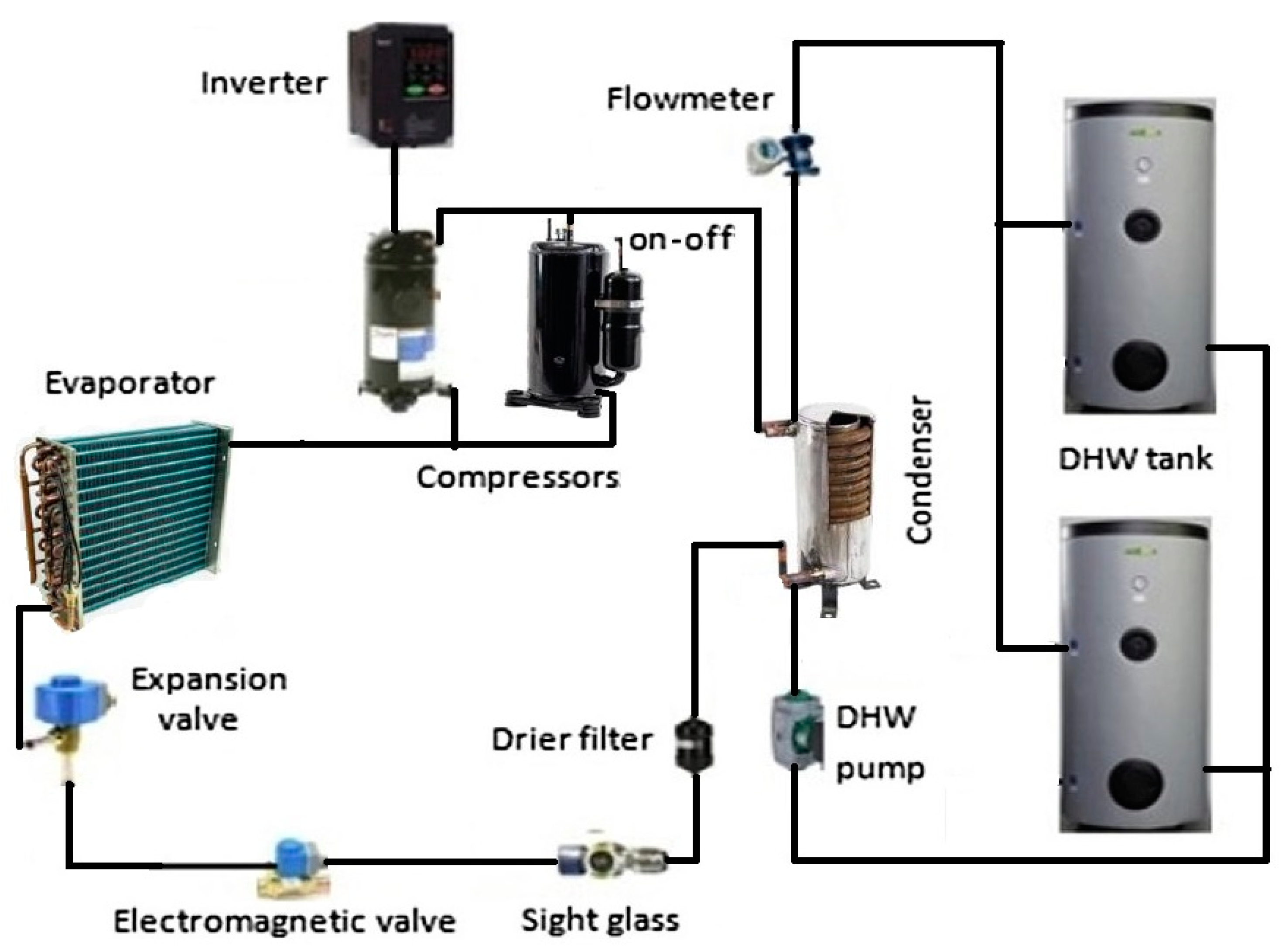
Figure 1 gives the basic characteristics of both compressors for the R410A refrigerant. The catalog data of the DA110S1C-30FZ compressor show that the allowable range of compressor operation is 30–90 Hz. The measuring series for this compressor was carried out in real conditions with 15 Hz steps. A dedicated Ruking iD826s inverter is offered by the manufacturer to drive this compressor. The Modbus RTU communication protocol is used for communication between the measuring and control system and the inverter. The connection diagram of individual components of the ASHP subsystem is presented in
Figure 2. The collection of heat energy from the heat pump is possible for two water tanks (0.13 m
3 each) independently. In this way, it was possible to carry out tests of a heat pump with a variable heat load. A standard 60 W circulation pump was applied for the water circulation at the heat pump outlet. Circulation pump settings made it possible to regulate the water flow rate in the range of 0.17–0.27 kg/s.
2.3. Measured Parameters and Data Acquisition
The extended, commercial Hewalex heat pump for DHW heating has been tested in real use conditions. Additional sensors for measuring important parameters which are necessary to perform energy analysis of thermodynamic processes in the heat pump were installed in the test stand. The test stand has been equipped with a specialized measurement and control system for controlling the heat pump and recording the measurement data.
To analyze the electricity consumption of each component during operation or to calculate COP values, electricity power meters were installed for all devices. Besides which, a second independent COP coefficient measuring system offered by the heat pump manufacturer as an additional device was installed in the test stand. In this way, a second independent measuring path was obtained with a data recording step at every 2 min.
The measurement data are recorded every 30 s in the basic measurement and control system. The set measurement frequency allows the determination of the instantaneous heating power and demand for electricity. Class A wattmeters (1% accuracy) were used to record electricity consumption. The heat energy produced by the ASHP is determined by measuring the mass flow rate of water at the condenser and measuring the inlet and outlet water temperature. The mass flow rate of water was measured by the Siemens MAG 1100F electromagnetic flow meter. Special PT100 Class A RTD sensors were used to measure water temperature. They are respectively paired and specially scaled. The registration of the heat flux is carried out with a measurement uncertainty below 1%. Basic parameters of the measurement and control system are given in
Table 2.
K-type thermocouples mounted on pipes with clamps and additionally thermally protected were used to measure temperatures in the freon cycle. The condensation and evaporation pressure measurements were carried out for R410A using pressure transducers AKS32R. The registration of the above parameters is necessary to perform an energy analysis in the ASHP subsystem.
In this test, the heating capacity
Q was calculated based on the Equation (1)
Input power demand
W was calculated based on the Equation (2)
Input power demand
Wmt of the Brushless DC motor was calculated by Equation (3)
The cooling capacity
Qc was calculated by Equation (4)
The COP of the ASHP subsystem at any time (
t) was calculated by Equation (5)
The average values of COP in each cycle was calculated by Equation (6)
The tested heat pump in the monoblock version is designed for central heating installations with solid fuel boilers. In this way, DHW production outside the heating season is carried out without the need to operate coal boilers which are harmful to the environment. Therefore, operational tests of the commercial heat pump were conducted for positive air temperatures supplied to the ASHP subsystem.
3. Experimental Results
The heat pump’s measuring cycles were carried out for outside air temperatures of 7, 15, 22 °C. During the measuring cycles, the water in the storage tank was heated from room temperature to the temperature above 50 °C. The measurement cycles were carried out for three cases of compressor operation:
factory fitted typical compressor,
additional inverter compressor,
simultaneous operation of two compressors.
3.1. Heat Pump with Fixed Speed Compressor
In this variant, the tests on the commercial heat pump were conducted under real operating conditions.
Figure 3 presents recorded changes in air temperature in the evaporator circuit and water temperature in the condenser circuit for profile A22/W30-50.
On average, 20 min after the start of the test cycle, the operating conditions in the refrigerant circuit stabilize. The difference in water temperature in the condenser was ∆Tw = 3.2 °C on average. In the presented example, a stable increase in evaporation temperature from 7 °C to 11 °C can be observed. At the start of the measurement, the air temperature difference in the evaporator circuit was ∆Ta = 16 °C, and at the end of the measurement was ∆Ta = 11 °C. During the measuring cycle, 6.92 kWh of heat energy was produced, 1.94 kWh of electricity was consumed, and COP = 3.61. For the determined thermodynamic balance of the heat pump, the evaporation temperature is comparable to the air temperature at the outlet of the evaporator.
Instantaneous COP and heating capacity values were determined every 30 s for each measurement cycle. Recorded data are shown in
Figure 4. The compressor input power increased from 660 W to 1050 W in proportion to the increase in condensing temperature.
In the whole measuring cycle, an average heating capacity of 3100 W was obtained. The instantaneous COP value for the compressor changed from 5.35 to 3.75. The additional devices (circulation pump, fan) consumed an average input power of 120 W. Finally, the average COP value for the measuring cycle dropped to 3.68. The heating capacity remained constant during the measurement cycle, while the demand for the compressor input power increased with increasing condensing temperature. Therefore, the demand for cooling power decreases, which results from the Equation (4). This explains the increase in evaporation temperature and the evaporator outlet air temperature.
Figure 5 presents the averaged values of heating power and COP for three values of the outside air temperature. As expected, the heat pump’s operating efficiency increases as the outside air temperature increases. On cool days, the heat pump’s energy efficiency decreases by 12%. The impact of the water flow rate on the energy efficiency of the tested heat pump was described in the previous author’s studies [
37].
3.2. Heat Pump with Variable Speed Compressor
An additional variable-speed compressor was installed on the test stand to test the impact of the compressor used on the heat pump’s efficiency. Measurement cycles were carried out in the same way as in the item above.
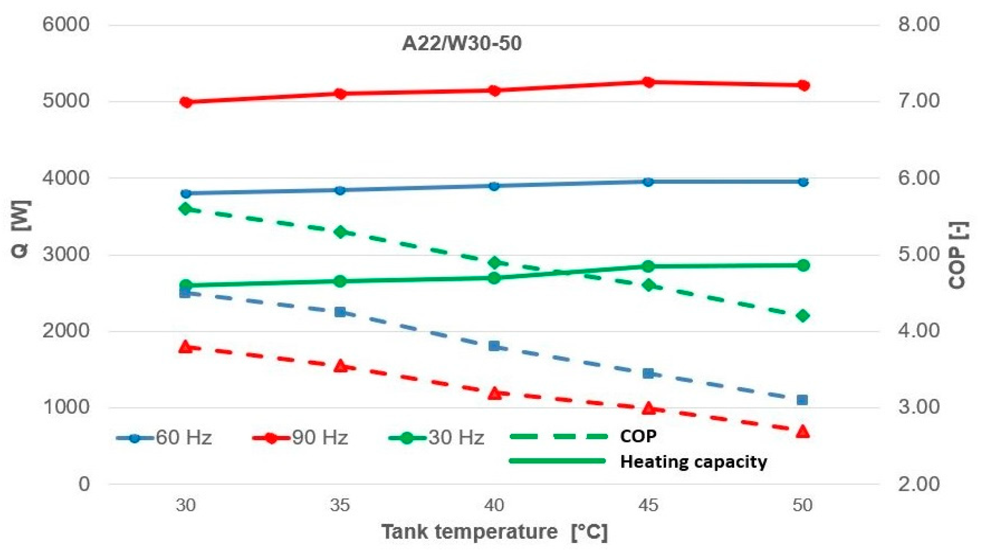
Figure 6 compares the COP value and heating capacity of the inverter compressor for profile A22/W30-50. The heat pump allows you to adjust the heating capacity in the range from 2700 W for 30 Hz to 5100 W for 90 Hz. The highest COP was obtained for the frequency of 30 Hz. The COP value decreased proportionally to the increase in condensing temperature in the range from 5.70 to 4.20 (falls by 25%). The lowest COP values were recorded for 90 Hz.
The impact of the outside temperature on the efficiency of the heat pump is shown in
Figure 7. At a frequency of 60 Hz, the heat pump has a heating capacity of 3900 W for profile A22/W30-50. A drop in outside temperature by every 7 °C forces a decrease in heating capacity by 6%. For the A22/W30-50 profile, the heat pump generates an average of 5.55 kWh of heat energy, consuming 1.55 kWh of electric energy with an average COP = 3.70.
Figure 8 shows the BLDC motor’s demand for input power needed to drive the compressor. The compressor input power demand increases in proportion to the increase in frequency and condensing temperature. The measurement results obtained are consistent with the catalog data given in
Figure 1 for a given evaporation temperature.
The Ruking inverter dedicated by the compressor supplier was used to drive the BLDC motor. From previous measurements carried out by the author a relatively low inverter efficiency of 80% was noted [
38]. Therefore, comparative tests were also carried out using the universal Invertek Optidrive E3 inverter. Comparative results are given in
Figure 9. From the measurements obtained it appears that the Optidrive inverter worked with an average efficiency of 90%.
3.3. Heat Pump Version with Two Compressors with Fixed and Variable Speed
The expansion of the commercial heat pump with a second compressor allows testing of the device with two compressors running simultaneously. Therefore, it is possible to perform additional tests of the effect of oversizing of compressor power on the energy efficiency of the heat pump. A chart of recorded temperature changes for the A22/W30-50 profile for two measuring cycles with 0.13 m
3 and 0.26 m
3 water tanks is given in
Figure 10. For a single water tank, a higher dynamics of water temperature increase in the condenser circuit was noted (increase of 30%). The diagram on the left shows a situation when a variable speed compressor was intentionally started 10 min after the start of the measuring cycle. It can be observed that the moment of switching on the second compressor introduces a momentary disturbance to the thermodynamic balance of the refrigerant circuit. A significant decrease in evaporation temperature is also visible. Besides which, the difference in the dynamics of the condenser water temperature increase for the case of switching on one and two compressors can be observed.
The comparison presented in
Figure 11 shows that the heat pump has obtained a heating capacity of 5000 W for stable operating conditions for a 0.13 m
3 storage tank and about 4000 W for 0.26 m
3 storage tanks. The graph on the right shows that for the same profile A22/W30-50, the heat pump achieved thermodynamic equilibrium at a lower evaporation temperature (decrease of 4 °C). The greater demand for cooling power causes a decrease in the air temperature in the evaporator circuit and in addition a decrease in evaporation temperature. As a result, the graph on the right shows a decrease in heating power by 1000 W and a decrease in the average COP value by 0.15.
Figure 12 represents the heating power and COP when the inverter compressor frequency is changing in the range 30, 45, 60 Hz. For the second and third case, the ASHP obtained a maximum heating power of 5000 W. A fixed speed compressor and an inverter compressor for 60 Hz individually obtain heating power above 3000 W. In the case of the simultaneous operation of two compressors, the maximum heating power of the ASHP is limited by the water flow rate and the heating power of the condenser (
Table 1). This means that the heating capacity of the condenser has been correctly selected in the design (appropriate oversizing). The highest energy efficiency was obtained for the second case, average values: 4900 W heating capacity, 1650 W input power, COP = 3.0 were obtained.
3.4. Energy and Economic Analysis
The summary of the measurement results presented in the points above shows that a heat pump with a fixed speed compressor can provide heating capacity in the range of 2200 W to 3100 W depending on the outside air temperature with an average COP value in the range of 3.2–4.6. Similarly, a heat pump with a variable speed compressor can generate heating capacity in the range of 2700 W to 5150 W, depending on current settings and current operating conditions.
Figure 13 shows a comparison of a heat pump operating parameters for the A22/W30-50 profile for three compressor configuration variants.
The diagram shows that for a variable-capacity compressor, a heat pump can provide a heating capacity in the range of 2700 W to 5100 W at frequencies in the range of 30–90 Hz. The input power increases on average by 38% in proportion to the increase in frequency and the heating capacity by 22%. The COP value, on the other hand, varies from 4.8 to 3.1 (a decrease of 35%). In the case of hybrid operation, higher heating capacity values were obtained but with a higher demand for input power, which resulted in lower COP values. The most beneficial effects were obtained for the inverter compressor in the low frequency range, but heating the water in the storage tank is burdened with extended operating time.
Figure 14 presents a summary of the daily electricity consumption for DHW production in a household for selected heat pump operation variants. As the compressor drive frequency increases, the electricity consumption increases linearly. Consequently, the unit cost of DHW preparation increases. The lowest operating costs are obtained at 30 Hz but they result in the heat pump’s extended operating time. For the 45 Hz frequency of the inverter compressor, the heating capacity was comparable to that of the fixed speed compressor, but a 10% lower daily cost of DHW was achieved. The impact of varying daily DHW demand can be reduced by using storage tanks with increased water capacity and, if possible, starting the heat pump in the low-frequency range. In the households heated with solid fuel boilers, not only does the production of DHW by means of a heat pump outside the winter season offer an economic and maintenance-free solution but also a positive effect on the environment.
4. Discussion
The overall energy efficiency of a heat pump under real operating conditions is influenced by many parameters characterizing the operating conditions of individual heat pump components [
39]. If the heat pump’s components have been chosen correctly, the choice of a compressor and drive method has a decisive impact on its overall efficiency. The use of a fixed speed compressor allows good operating parameters to be achieved only for optimal conditions of use. As expected, in the case of a variable speed compressor, an increase in heating capacity was obtained in proportion to the increase in compressor frequency and a decrease in COP with an increase in condensing temperature. The obtained research results are consistent with the research results presented by other research teams. Wang et al. [
40] conducted tests of the inverter heat pump in the frequency range from 50 Hz to 110 Hz in 10 Hz steps and with a constant condensing temperature set at 45, 55, 65 and 75 °C. The available research results from constant speed compressor driven heat pumps and variable speed compressor heat pumps show that an inverter-driven heat pump is an effective way to improve the annual energy saving due to better partial load efficiency. Cuevas et al. [
41] reported that the losses of the electric motor attributable to the use of the inverter are insignificant, as the tested inverters worked with efficiency in the range of 95–98%. Karlsson and Fahlen [
42] proved that there is no improvement in the annual energy efficiency of an inverter-driven heat pump compared to a conventional fixed speed heat pump, mainly due to the inefficient operation of the inverter and compressor motor. Chae and Ren [
43] carried out tests of a heat pump equipped with two compressors with fixed and variable speed. They showed that a fixed speed compressor can run more efficiently under constant load conditions, meeting 50% of the heat demand. In the event of increased instantaneous heat demand, the inverter compressor is switched on at part load. The results obtained in this article show that compared to a single inverter compressor operation at 90 Hz, hybrid operation (50 Hz fixed speed + 30 Hz inverter) produced a comparable amount of heat but with a 15% lower COP.
5. Conclusions
The energy efficiency of an air source heat pump with fixed and variable speed compressors for hot water production was examined in this study. The obtained experimental results confirm that the heating capacity of the tested heat pump is sufficient to cover the demand for the thermal energy needed to prepare domestic hot water. The heat pump performance remained constant during each measurement cycle for stable operating conditions. The heating capacity of the heat pump with a fixed speed compressor varied from 2700 W for an outside air temperature of 7 °C to 3200 W for an air temperature of 22 °C. COP values changed in the range of COP = 3.2–4.6, respectively.
For the heat pump variant with a variable speed compressor in proportion to the 30–90 Hz frequency range, the heat pump heating capacity varied from 2700 W to 5100 W, and the COP value was in the 3.1–4.80 range, respectively. The refrigerant’s condensing temperature has a significant impact on the instantaneous COP value. On cool days, the average heating capacity of the heat pump decreases by 12%. A variable heat pump ensures flexible adaptation of the heating capacity to the varying hot water demand. If possible, it is recommended to prepare DHW in the lower frequency range which results in the lowest operating costs. However, the extended working time is needed to perform this task. For heating DHW, it is most advantageous to use an oversized, variable speed compressor operating in the lower frequency range.


