Abstract
In order to implement moderate or intensive low oxygen dilution (MILD) combustion, it is necessary to extend the flame stability and operating range. In the present study, the conceptual designs of a combustor single nozzle and reformer were numerically suggested for a micro-gas turbine with an on-board reformer. The target micro-gas turbine achieved a thermal power of 150 kW and a turbine inlet temperature (TIT) of 1200 K. Studies on a nozzle and reformer applying an open-loop concept have been separately conducted. For the nozzle concept, a single down-scaled nozzle was applied based on a reference nozzle for a heavy-duty gas turbine. The nozzle can achieve a good mixture with a high swirl with a splined swirl curve lower NOx emissions and smaller pressure drop in the combustor. The concept of the non-catalytic partial-oxidation reforming reformate was designed using the combustor outlet temperature (COT) of the exhaust gas. Feasible hydrogen yields were mapped through the reformer. Based on the hydrogen yields from the reformer, hydrogen was added to the nozzle to investigate its combustion behavior. By increasing the hydrogen addition and decreasing the O2 fraction, the OH concentrations were decreased and widely distributed similar to the fundamental characteristics of MILD combustion.
1. Introduction
Global warming has become a major issue as greenhouse gas emissions have increased, and the average global temperature is expected to increase by 1.4% to 5.8% by 2100. The main factors influencing the greenhouse effect are carbon dioxide (CO2), chlorofluorocarbons (CFCs), methane (CH4), and nitrous oxide (N2O) at rates of 55%, 24%, 15%, and 6%, respectively. This indicates that CO2 has had the largest impact [1].
In addition, [2] Demirbas demonstrated that global CO2 emissions from 1990 to 2020 have rapidly increased with an increase in industrial output. It is therefore necessary for humanity to reduce such emissions for sustainable development.
Among the various reasons for CO2 generation, the most important is the use of fossil fuels for generating power. According to [2], 98% of CO2 generation is generated by fossil-fueled power generating facilities [3]. One way to solve this problem is to diversify the fuel species to include biomass. Table 1 shows the composition of natural gas and it can be seen that methane, a type of biomass, occupies a significant amount. Methane has an advantage of less CO and CO2 emissions owing to its molecular structure, in which the ratio of carbon to hydrogen is relatively small compared to that of conventional hydrocarbon-based fuels. Gas turbine power generating systems using methane are expected to contribute significantly to a reduction of CO2 emissions from coal-fired power plants, and research on gas turbine combustors is actively being conducted. The following expression is a key to sustainable development [4]:
Economy + Ecology + Society = Sustainability

Table 1.
Typical composition (Vol %) natural gas [5].
To achieve sustainable development in the gas turbine field, it is necessary to secure economic feasibility through an improvement in combustion technologies and technologies for reducing emissions, although achieving both goals will be difficult. Because moderate or intensive low oxygen dilution (MILD) combustion is based on lean combustion, it can reduce fuel consumption and is economically sound. In addition, as a new combustion technology, MILD combustion, is attracting significant attention as a way to achieve sustainable development because it reduces emissions after combustion while reaching the target performance. MILD combustion or colorless distribution combustion (CDC) is called flameless combustion or flameless oxidation, which is not observed due to low OH concentration. The following shows the main characteristics of a MILD combustion.
- Better fuel flexibility.
- Diluted concentration of internal oxidant through exhaust gas recirculation (EGR).
- Reduced nitrogen oxide emissions through low-temperature combustion.
To realize a MILD combustion, there are two requirements: realizing a lean combustion through an improved mixture and expanding the operating range through the addition of dual fuel.
First, a MILD combustion has the advantage of a COX reduction by reducing the fuel quantity through a lean combustion and reducing the thermal NOX owing to a low combustion temperature [6,7]. To implement a MILD combustion, it is necessary to aim for a lean operation and prevent a local temperature increase inside the combustor.
However, a lean combustion using methane as a single fuel source requires an extended flame limit because of its narrow operating range and instability [8,9].
To meet these demands, a number of prior studies have been conducted on the use of dual fuels that can extend the combustion limit by mixing additional fuels with the main fuel. Sun considered the flame characteristics to measure the turbulent flame in a dual-fuel combustion environment in which pre-mixed fuel and hydrogen were added for combustion. Through the reasons for the increase in turbulence intensity, more initial cracks are induced on wrinkling curvatures, and the development of the initial cracks is accelerated. Due to hydrodynamic instability, it is strengthened by increasing the density ratio across the flame front [10].
In addition to a basic study of flame characteristics, a study on dual fuels has been actively carried out on the application of internal combustion engines. et al. conducted a study on the expansion of the operating range using hydrogen in diesel engines. In the study, for a single injection model, it was confirmed that the effect of added hydrogen was significant. However, when comparing the experiment and simulation analysis, the tendency of the heat release rate and the pressure in the cylinder to be lowered was confirmed [11]. It was confirmed that this tendency decreases even more in the case of a multi-stage injection. In addition, studies on the extension of the operating range through the addition of dual fuels in various types of fuels such as CNG and LNG are actively being conducted [12,13]. In diesel engines, the addition of CNG has resulted in a longer ignition delay, shorter combustion duration, and improved peak pressure in both single injection and multi-stage injection. In addition, because the addition of LNG increases the temperature inside the cylinder, it has been indicated that this is the primary reason for the formation of thermal NOX at medium loads. By contrast, the increase in NOX emissions is negligible because NOX emissions are insignificant at low loads. Research on the application of a dual fuel is not dependent on the engine and has been actively conducted in the field of gas turbines. Meziane and Bentebbiche [14] studied the characteristics of flames inside a combustor, and analyzed the operation limit range through the combustion of multiple types of fuel.
Currently, hydrogen is the most actively studied among dual-fuel types. This is due to the properties of hydrogen, which is a molecule composed of a single H atom in its molecular structure, and because carbon is not present, it has the advantage of a COX-free combustion. According to Koten et al. [15], it has been proven to have a high combustion rate through a high reactivity, diffusivity, and energy release, and it increases the thermal efficiency in an internal combustion engine. The feasibility of extending the operation limit range by adding hydrogen for a leaner combustion has been proven. However, hydrogen has some limitations applied to a hydrogen-based combustion system.
- A higher combustion temperature when generating thermal NOX.
- A lower efficiency required for production and storage owing to the large volume per unit mass.
Owing to its specific nature, the high energy release generated during a hydrogen reaction increases the reactivity of the fuel, but causes a local increase in temperature, leading to an increase in thermal NOx emissions [16,17]. These problems can be solved through EGR. Exhaust gas contains various components, including water vapor, and can provide an environment with a low concentration of oxidants. The water vapor in the exhaust gas participates in combustion to prevent the combustion temperature owing to the large specific heat of the water vapor. At the same time, it is possible to prevent the combustion temperature by increasing the concentration of the oxidizing agent [18].
Moreover, hydrogen is difficult to commercialize because of its large volume per unit mass and low production and storage efficiency. A solution to this problem is on-board reforming through a reforming reaction. Reforming uses the waste heat generated during combustion to form syngas through hydrocarbon-based fuels, and hydrogen production, storage, and utilization can be unified by participating in this combustion [19,20].
On-board reforming has been conducted by many prior studies to realize lean combustion in vehicle engines [21,22], although customized reforming systems in gas turbines have been relatively lacking in terms of research.
In the present study, the feasibility of MILD combustion with hydrogen addition was numerically conducted by considering an on-board reforming system with a single nozzle for a micro-gas turbine engine. To confirm the independent performance, the combustor and the reformer were studied separately. To derive the H2 yield generated from the reformer and simulate on-board reforming, a study was conducted to add it to the combustor in an open-loop form. In the future, hydrogen generated from the reformer will be introduced into the combustor, and research on extending the system to a closed-loop that simultaneously analyzes the conditions at the same time has been planned. A schematic diagram of the overall study flow of this paper is shown in Figure 1.
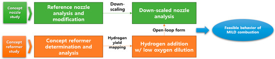
Figure 1.
Overall research flow.
2. Methodologies
2.1. Modeling Description
The commercial computational fluid dynamic (CFD) program used in this study (i.e., CONVERGE™) is mesh free and aims for an automatic mesh refinement (AMR), which is an automatic grid segmentation technology. The original use is a program developed to facilitate the analysis of a movable lattice such as an internal combustion engine, although a combustion CFD analysis has been actively conducted with the recent activation of research and development into gas turbine combustors. The following shows the governing equation and boundary conditions used in the modeling.
A fluid analysis is impossible in a fixed coordinate system, as it is often not used in such a form, unlike that of which is determined through a typical solid analysis. The Navier–Stokes equation was applied to the analysis system for a fluid with viscosity by using Newton’s law of motion:
The turbulent flow model was used to simulate the average flow properties of the turbulent flow conditions. The basic assumption of the RNG turbulence model is used when the isotropic turbulent viscosity state is applied. In the above equation, represents the turbulent kinetic energy, and represents the rate of loss of turbulent kinetic energy.
The scalar value of the sub-grid is estimated and the method of subdivision is used when the scalar threshold of the user-specified grid scale in the program is exceeded. The size of the maximum mesh subdivided by the maximum embedding level based on the base grid scale in the AMR is used.
In the Taylor series, is the factorial of n, and represents the derivative n of f in a:
2.2. SAGE Chemistry Model
The SAGE detailed chemistry model is a detailed chemistry solver used to simulate the combustion process. Here, it was used to calculate the reaction rate based on the chemical reaction. It is typically used for modeling emissions of premixed combustion along with the GRI 3.0 mechanism. The combustion model based on the Arrhenius equation calculates the mass fraction in the cell according to the time step. In the Arrhenius equation expression, represents a pre-exponential factor, and indicates activation energy. In the SAGE model, the mass fraction transport equations of the above expression represents the source term.
To describe the detailed chemical reactions of combustion, the GRI 3.0 mechanism was used. The GRI 3.0 mechanism [23] is suitable for a combustion of methane-based fuels and includes 325 basic reactions with 53 species. The GRI 3.0 mechanism was used to chemically model the formation and reproduction of NOX. It was also used to concreate the modifier environment of the composition of syngas generation through the methane in the modifier.
2.3. Concept Nozzle Determination
2.3.1. Reference Single Nozzle Specification for H-Class Gas Turbine
The reference nozzle was an H-class gas turbine combustor nozzle under development. The target turbine inlet temperature (TIT) was 1873 K, and detailed specifications of the operating conditions and geometric information are shown in Table 2. The center body length and diameter of the nozzle, swirler length/angle, mixing length confined ratio, nozzle casing diameter, offset length, combustor length and diameter, number of fuel injection holes, and diameter of the nozzle were modeled based on the specifications of the reference nozzle. This was used to judge the model accuracy of the CFD analysis in terms of the TIT. Figure 2 shows the geometry of the reference nozzle. The fuel injection type is a jet in cross, and the combustion method is a lean premixed combustion type. The swirl of the base nozzle was composed of a perfect mixing type located as close as possible to the entrance of the center body, and was analyzed by dividing it into a low swirl case that achieved the target TIT of 1873 K and a high swirl to improve mixing. Based on the analysis results, downscaling was conducted using a high swirl type as the final reference nozzle to implement a down-scaled single nozzle, as mentioned in Section 2.3.2. Please note that it is difficult to provide detailed nozzle specifications such as the geometric ratio owing to a non-disclosure agreement.
Table 2.
Boundary condition and specification for reference single nozzle.
Figure 2.
Reference single nozzle geometry and specification.
2.3.2. Down-Scaled Single Nozzle Specification for the Present Study
Based on the H-class nozzle, it was changed to the target nozzle by down-scaling to a combustor nozzle corresponding to a heat output of 150 kWth and a TIT of 1200 K. The target nozzle is a small nozzle for realizing a micro-gas turbine. The ratio to the geometry was referred to the reference nozzle by using the combustion loading parameter (CLP) and combustion intensity calculation, which are commonly applied when designing combustion equipment [24,25]. The combustion loading parameter in SI units is as follows:
In the above equation, the combustor volume represents the liner volume. represent the temperature and pressure of the combustor inlet, respectively. The calculated volume calculated in Equation (12) was verified as the combustion intensity:
where is the fuel mass flow rate and LHV is the fuel lower calorific value (kJ/kg). Table 3 shows the down-scaled single-nozzle operating conditions. Figure 3 shows a downscaled target nozzle, which has a layout similar to that of the reference nozzle except for the swirl number and swirl geometry. The swirl number was calculated using Equation (13) based on the swirl geometry in Figure 3. In addition, to increase the number of swirls in the final reference nozzle, in case 2 of the reference nozzle, the geometry was changed to a splined curve type swirler to induce a high swirl motion with a swirl number of 0.8.
Table 3.
Boundary conditions and specifications for down-scaled single nozzle.
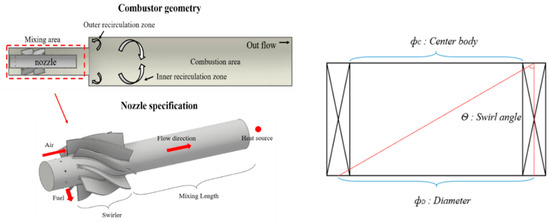
Figure 3.
Down-scaled single nozzle and combustor geometry.
2.4. Concept of Reformer Determination
The reformate of the concept reformer is methane, which is also used as the main fuel for combustion. The reforming reaction using methane can be seen in three main ways: partial oxidation reforming, CO2 reforming, and steam reforming [23].
The reaction formula above is for partial oxidation reforming, CO2 reforming, and steam reforming reaction mechanisms, and includes the reaction of carbon coupling and hydrogen combustion. To proceed with the reforming using a high-temperature exhaust gas extracted from the gas turbine combustor, it was concluded that partial oxidation reforming is suitable.
The reforming layout used in our study is on-board with reforming that uses a closed-loop cycle via EGR (referred to as a reformed EGR). Figure 4 shows a schematic diagram of the reformed EGR with a combustor, which is our final goal.
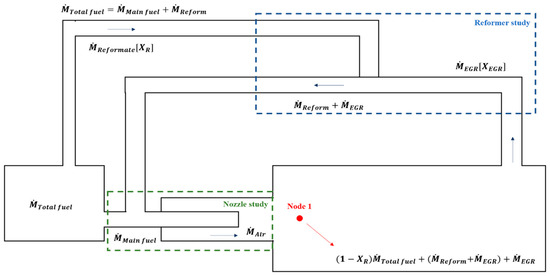
Figure 4.
Schematic of concept exhaust gas recirculation (EGR) loop based on mass flow.
For the concept of a reformer analysis, the first step in defining the operating conditions of the reformer loop is to determine the recirculation rate of the EGR.
To calculate the recirculation rate of the reformer, a basic mass balance was applied, as shown in Figure 4. Using mass balance equations, the mass of the reformate and EGR was calculated while maintaining the equivalence ratio and TIT for the target thermal power output. It was also derived from the EGR mass flow rate and hydrogen yield based on the chemical equilibrium when considering the mass balance and the thermal and chemical properties of the combustion products, which are used as input data for EGR inlet conditions.
To obtain an efficient reforming yield from partial oxidation, the heating area was widened considering the total volume of the reformer, which is calculated from the EGR mass flow rate and the EGR rate itself. Therefore, parametric studies for a reformer design were conducted to compare the reforming performance based on the concept geometry shown in Figure 5. By varying the reaction temperature, which represents the EGR inlet temperature and total volume of the reformer listed in Table 4, hydrogen yields were mapped as a contour form, and proper operating conditions were selected.
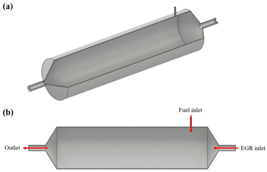
Figure 5.
Concept reformer geometry: (a) quarter view; (b) side view.
Table 4.
Parameter ranges for hydrogen yield from reformer.
2.5. Hydrogen Addition on Down-Scaled Nozzle
As mentioned in the introduction section, it was assumed that the produced hydrogen content (in volume) from the reforming was directly input to the concept nozzle in the form of an open-loop. By adding hydrogen, feasible hydrogen contents from reforming were confirmed, and the hydrogen-added combustion behavior is discussed in Section 3.3.
The closed-loop analysis will be completed and introduced in our upcoming study.
3. Results and Discussion
3.1. Reference Nozzle Analysis Results
Figure 6 shows the results of non-reacting and reacting flow analyses of the reference nozzle. Figure 6a shows that the mixedness of case 2 with relatively high swirl number is better. Figure 6b shows the temperature distribution during the reacting flow. As can be seen in the figure, the flame distribution in case 2 is more evenly distributed than case 1. In addition, to confirm the thermal effect on the turbine blade, the temperature distribution at the outlet end of the combustor is as shown in Figure 6c. It can be seen that the temperature distribution in case 2 with a high swirl number is relatively even. According to the results, a modification of the swirl number can enhance the mixedness and decrease the reaction temperature compared to the reference nozzle in case 1.
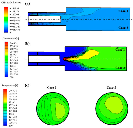
Figure 6.
(a) Fuel concentration under non-reacting flow of reference nozzle. (b) Temperature distribution under reacting flow of reference nozzle. (c) Temperature distribution under reacting flow at the combustor outlet reference nozzle.
Figure 7 shows the average temperature at the combustor outlet, which has an effect on the TIT. The average combustor outlet temperature (COT) of case 1, which has a perfect mixing type and low swirl, is 1854 K. It can be seen that this is close to 1873 K of the target TIT, which is the test results with an error bar for the H-class combustor. By contrast, it can be seen that case 2, which has a perfect mixing type and high swirl, has a COT of 1748 K owing to the increased mixing phenomena from a high swirl. Because MILD combustion requires the realization of combustion through a high mixedness, it was reasonable to select the final reference nozzle for the down-scale nozzle.
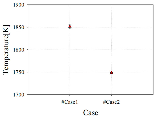
Figure 7.
Average combustor outlet temperature (COT) of reference nozzle with test result from case 1.
Figure 8 shows the pressure drop from the inlet of the combustor nozzle to the combustor outlet in case 2. It was confirmed that the pressure loss was 6.7%, which was relatively large considering that the pressure drop occurring in a conventional combustor was within 5%.
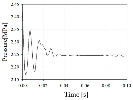
Figure 8.
Internal pressure of reference nozzle with case 2.
3.2. Down-Scaled Nozzle Analysis Results
Figure 9 shows the analysis results of the downscaled nozzle. The left side of Figure 9a shows the internal geometry of the nozzle casing, and the right side shows the results derived through the analysis. It can be seen that the flow inside the combustor passes through the swirler, and a relatively slow flow regime is distributed in the mixing length. As a result, it was confirmed that methane was mixed with the inflow air and introduced into the combustion area.
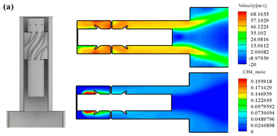
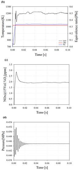
Figure 9.
(a) Internal velocity and fuel concentration of down-scaled nozzle. (b) Combustion outlet temperature and equivalence ratio of down-scaled nozzle. (c) NOx emission of the down-scaled nozzle. (d) Internal pressure of down-scaled nozzle.
Figure 9b represents the COT and equivalence ratio. The average COT is 1209 K and the operating equivalence ratio is 0.335. The equivalence ratio of a lean blow out (LBO) is 0.32. The LBO represents a lean combustion limit and is an important factor limiting the operating range for implementing a lean premixed combustion.
Figure 9c shows the average NOX emission at the end of the combustor outlet. Owing to the increase during the initial reaction, a peak of the thermal NOX emission occurs, but thereafter decreases and shows a tendency to converge. The concept nozzle can result in less NOx emissions than the target NOx.
Figure 9d shows the internal pressure convergence. The total pressure drop in the downscaled combustor appeared at 1.2% from the inlet of the combustor nozzle to the combustor outlet.
Based on a downscaled nozzle analysis, the concept nozzle can achieve better NOx emissions and less pressure drop under a lean combustion region with a high swirl.
3.3. Hydrogen Yield From Reformer Study
Figure 10 shows the results from a parametric study of a reformer with respect to the hydrogen yield as a function of the reaction temperature and reformer volume. As shown in the figure, the contour remarks are classified as two colors: yellow and green. In the contour shown in yellow, the production rates of hydrogen could not meet a proper yield of 9.4249e−6 kg/s, which is 20% of the total fuel and the maximum target of the hydrogen content in volume percent. By contrast, for the contour in green, the production rates of hydrogen could meet the proper yield of 9.4249e−6 kg/s, which is 20% of total fuel and the maximum target of the hydrogen content in volume percent. If the combustion outlet temperature or TIT is the desired value for hydrogen, it is reasonable to select the design point under 1200 K, as indicated by the green mark. In this study, the DP shown in Figure 10 was selected as the design point of the reformer representing the marginal operating conditions for the reformer.
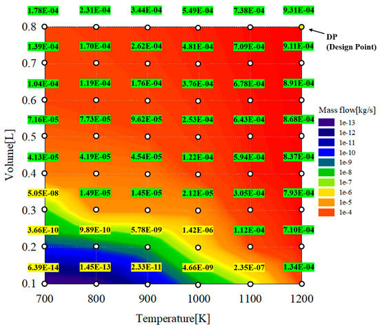
Figure 10.
Hydrogen yield contour as a function of reaction temperature and reformer volume.
To confirm the change in the amount of hydrogen generated according to the change in the reaction temperature and volume flowing into the reformer, parametric studies were conducted based on the information in Table 4. The reaction temperature represents the temperature of the exhaust gas extracted from the outlet of the combustor, and the volume was changed to increase the residence time of the reactants. Thus, the reformate amount and reformer design were selected to obtain the target hydrogen contents. The maximum target of the hydrogen content is 20 vol% when considering an inlet pressure of 4.5 bar at the maximum load.
Figure 11 shows the reforming results at the DP. As shown in Figure 11a, the reformer reaches a constant temperature after the reaction, and a higher temperature is maintained compared to the reaction temperature, which is referred to as the EGR inlet temperature. This implies that a partial oxidation exothermic reaction is more dominant than the other potential reforming reactions.
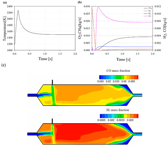
Figure 11.
(a) Temperature profile in reformer at design point (DP). (b) Chemical species profile during reforming at DP. (c) Distribution of CO and H2 inside the reformer at DP.
Figure 11b shows the reforming results of the representative chemical species at the DP. By consuming CH4 as a reformate and O2 as an oxidant, H2 and CO are produced, which are well-known syngas compositions. They are driven by partial oxidation processes.
Figure 11c shows the contour of the reformer at 1.5 s of the DP. As a result of the contour, it can be seen that CO and H2, which are reforming products of the reformed EGR gas, are formed by a chemical reaction between the high-temperature exhaust gas and CH4 as a reformate.
Based on the results of a previous study, it was found that a feasible hydrogen yield could be achieved based on the concept reformer. If a reformer control is considered and optimized, the addition of hydrogen to the combustor nozzle can be verified as below 20 vol%.
3.4. Hydrogen Addition on Combustor Nozzle
Figure 12 shows the results of a combustion analysis considering the hydrogen addition in volume percent. Figure 12a shows the COT as a function of hydrogen addition and O2 mass flow. The white marked points represent a combustible point considering the target TIT. As the hydrogen addition increases, it is confirmed that the operating ranges are expanded under lower oxygen conditions. The yellow marks in the contour represents the region where the oxygen is highly diluted and selected as the target operating points.
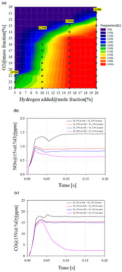
Figure 12.
(a) COT as a function of hydrogen addition and O2 mass flow. (b) NOx emissions with various hydrogen additions and oxygen conditions. (c) CO emissions with various hydrogen addition and oxygen conditions.
Figure 12b,c show the emission characteristics of hydrogen added combustion. In Figure 12b, it was confirmed that the NOX emission tends to decrease when oxygen is diluted under a hydrogen addition. In particular, with 20% hydrogen addition, NOX emission decreases by more than 0.7 ppm compared to 5% hydrogen addition. Although hydrogen can cause a higher combustion temperature owing to its reactivity, the oxidation environment of nitrogen is restricted by a lower oxygen environment, resulting in decreased NOx emission. In Figure 12c, the CO emission decreases as the amount of hydrogen increases. In particular, when 20% hydrogen is added, it can be seen that CO emissions are significantly reduced. This is because the mass flow rate of the total fuel flowing into the combustor is fixed despite the addition of hydrogen. In addition, the mass flow rate of the methane decreases, and it is judged that the carbon-based product, CO emissions, decreases.
Internal OH Distribution of Combustor
The OH mass fraction with 0% H2 in volume and 23% O2 in mass is shown in Figure 13a with the iso-surface and time variations. OH is produced by a chemical reaction during combustion and has an optically glowing property. Moreover, it is an important factor for evaluating the implementation of a MILD combustion.
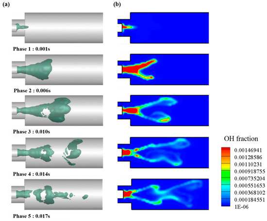
Figure 13.
Representative case of 0% of H2 in volume and 23% of O2 in mass. (a) Iso-surface of OH mass fraction; (b) plane OH mass fraction.
In phase 1, OH is generated by the combustion reaction when the fuel passes through the mixing area and through the combustion area after passing through the mixing area. As can be seen in each phase, OH is distributed around the heat source and can be seen to propagate into the surroundings. In phase 3, OH-rich region is dispersed owing to the turbulence of the internal flow, and an inner recirculation zone (IRZ) shape inside the combustor appears. IRZ affects the combustion re-engagement of the internal flow and the stability of the flame.
Figure 14 shows the OH distribution under different H2 addition and O2 dilution conditions for the reacting flow. The OH-rich region is distributed in the heat source and central region of the combustor for every case. By increasing the hydrogen addition and decreasing the O2 fraction, the OH concentrations decreased and were widely distributed. Particularly for the case of 20% H2 in volume with highly diluted oxygen, OH concentrations are remarkably decreased, with a combustion behavior similar to that of a MILD combustion.
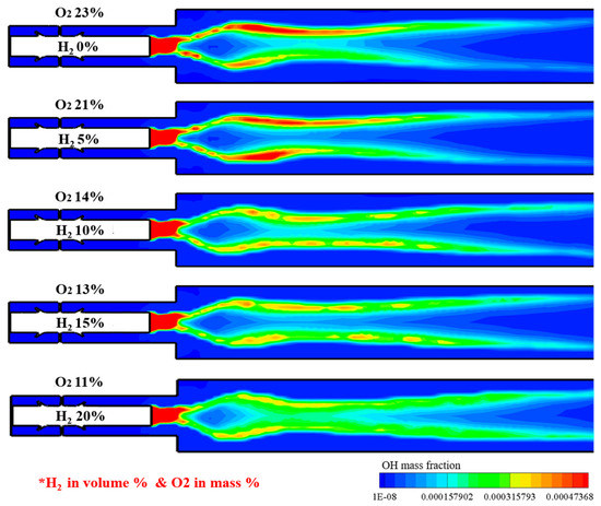
Figure 14.
OH distribution under different H2 addition and O2 dilution conditions for reacting flow.
4. Conclusions
In the present study, a conceptual design of a combustor nozzle and reformer was numerically suggested for a micro-gas turbine with an on-board reformer. Nozzle and reformer studies were conducted separately based on an open-loop concept. The key findings are as follows:
- Based on the reference nozzle for a heavy-duty gas turbine, a down-scaled nozzle was designed and analyzed. The main characteristics of the down-scaled nozzle are a DLN (dry low NOX)-type with high swirl with a perfect mixing concept to obtain a lean premixed combustion. A down-scaled nozzle had an average TIT of 1209 K, which was satisfied within ±5% of the reliability range of the combustor model with a target TIT of 1200 K. In addition, the NOx emission less than the target NOx emission of 5 ppm was satisfied, and the pressure loss at the inlet to outlet reached 1.2%.
- To design the conceived reformer, mass balance calculations considering the closed-loop cycle with reformed EGR and operating conditions were found. By conducting a parametric study for the reformer design, the hydrogen yield was mapped and the design point was selected. The conceived reformer can meet the proper hydrogen yield, reflecting 20% of the maximum target hydrogen content in volume percent considering an inlet pressure of 4.5 bar at the maximum load. It seems that the reforming process was dominantly driven by partial a non-catalytic oxidation.
- With the feasible hydrogen yield obtained from a previous study, hydrogen additions with various O2 diluted conditions were described using a down-scaled nozzle. By increasing the hydrogen addition and decreasing the O2 fraction, OH concentrations were decreased and widely distributed, which was similar to the fundamental characteristics of a MILD combustion.
- The remaining task of this study is to convert the model from an open-loop to a closed-loop cycle. To realize the closed-loop cycle shown in Figure 15, the key idea is to induce the reformed gas directly into the inner passage of the nozzle by force, which is expressed as a box in Figure 15. To make sense of this, a specific auxiliary component will be introduced in a future study. Moreover, the reformed EGR control layout will be also included.
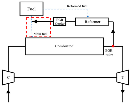 Figure 15. Final target Brayton cycle with reformed EGR loop.
 - For further work, a lab-scale test is planned to verify the flame structure obtained from the present work.
Author Contributions
Conceptualization, methodology, validation, formal analysis, investigation and writing—original draft preparation, J.K., Supervision, funding source, writing—review and editing, J.P. All authors have read and agreed to the published version of the manuscript.
Funding
This research was funded by the Korea Electric Power Corporation (Grant no. R19XO01-35).
Conflicts of Interest
The authors declare no conflict of interest.
Abbreviations
| Turbulent kinetic energy | |
| Rate of dissipation of turbulent kinetic energy | |
| n! | Factorial of n |
| th derivate of evaluated at point | |
| Pre-exponential factor | |
| Activation energy | |
| Source term | |
| AMR | Adaptive mesh refinement |
| CDC | Colorless distribution combustion |
| CFD | Computational fluid dynamic |
| CLP | Combustion loading parameter |
| CO | Carbon monoxide |
| CO2 | Carbon dioxide |
| COT | Combustor outlet temperature |
| DLN | Dry low NOX |
| EGR | Exhaust gas recirculation |
| HILS | Hardware in the loop simulation |
| LBO | Lean blow out |
| MILD | Moderate or intensive low oxygen dilution |
| NOX | Nitrogen oxides |
| OH | Hydroxy group |
| SS | Swirl support |
| TIT | Turbine inlet temperature |
| 3D | Three dimensional |
References
- Demirbas, A. Carbon dioxide emissions and carbonation sensors. Energy Sources Part A 2008, 30, 70–78. [Google Scholar] [CrossRef]
- Demirbas, A. Potential applications of renewable energy sources, biomass combustion problems in boiler power systems and combustion related environment issues. Prog. Energy Combust. Sci. 2005, 31, 171–192. [Google Scholar] [CrossRef]
- Rasul, M.G.; Khan, M.M.K. A review on technologies for reducing CO2 emission from coal fired power plants. Therm. Power Plants 2012. [Google Scholar] [CrossRef]
- Okokpujie, I.; Fayomi, O.; Oyedepo, S. The role of mechanical engineers in achieving sustainable development goals. Procedia Manuf. 2019, 35, 782–788. [Google Scholar] [CrossRef]
- U.S. Energy Information Administration (EIA). Annual Energy Outlook 2018 with Projection to 2050. Available online: https://www.eia.gov/outlooks/aeo/pdf/AEO2018.pdf (accessed on 6 February 2018).
- Hasemann, S.; Huber, A.; Naumann, C.; Aigner, M. Investigation of a FLOX®-based combustor for a micro gas turbine with exhaust gas recirculation. In Proceedings of the ASME Turbo Expo 2017 Turbomachinery Technical Conference and Exposition, Charlotte, NC, USA, 26–30 June 2017; American Society of Mechanical Engineers: New York, NY, USA, 2017. GT2017-64396. [Google Scholar]
- Kruse, S.; Kerschgens, B.; Berger, L.; Varea, E.; Pitsch, H. Experimental and numerical study of MILD combustion for gas turbine applications. Appl. Energy 2015, 148, 456–465. [Google Scholar] [CrossRef]
- Verhelst, S. Recent progress in the use of hydrogen as a fuel for internal combustion engines. Int. J. Hydrogen Energy 2014, 39, 1071–1085. [Google Scholar] [CrossRef]
- Zhai, X.; Liu, K.; Yao, Q. New Energy Technology; Chemical Industry Press: Beijing, China, 2010. [Google Scholar]
- Sun, Z.Y. Structure of turbulent rich hydrogen-air premixed flames. Int. J. Energy Res. 2015, 35, 2727–2791. [Google Scholar] [CrossRef]
- Tüchler, S.; Dimitriou, P. On the capabilities and limitations of predictive, multi-zone combustion models for hydrogen-diesel dual fuel operation. Int. J. Hydrogen Energy 2019, 44, 18517–18531. [Google Scholar] [CrossRef]
- Zhou, H.; Li, X.; Lee, C.F. Investigation on soot emissions from diesel-CNG dual-fuel. Int. J. Hydrogen Energy 2019, 44, 9438–9449. [Google Scholar] [CrossRef]
- Zhang, C.; Zhou, A.; Shen, Y.; Li, Y.; Shi, Q. Effects of combustion duration characteristic on the brake thermal efficiency and NOx emission of a turbocharged diesel engine fueled with diesel-LNG dual-fuel. Appl. Therm. Eng. 2017, 127, 312–318. [Google Scholar] [CrossRef]
- Meziane, S.; Bentebbiche, A. Numerical study of blended fuel natural gas-hydrogen combustion in rich/quench/lean combustor of a micro gas turbine. Int. J. Hydrogen Energy 2019, 44, 15610–15621. [Google Scholar] [CrossRef]
- Koten, H. Hydrogen effects on the diesel engine performance and emissions. Int. J. Hydrogen Energy 2018, 43, 10511–10519. [Google Scholar] [CrossRef]
- Nag, S.; Sharma, P.; Gupta, A.; Dhar, A. Experimental study of engine performance and emissions for hydrogen diesel dual fuel engine with exhaust gas recirculation. Int. J. Hydrogen Energy 2019, 44, 12163–12175. [Google Scholar] [CrossRef]
- Ceviz, M.A.; Sen, A.K.; Küleri, A.K.; Öner, I.V. Engine performance, exhaust emissions, and cyclic variations in a lean-burn SI engine fueled by gasoline–hydrogen blends. Appl. Therm. Eng. 2012, 36, 314–324. [Google Scholar] [CrossRef]
- Elkady, A.M.; Evulet, A.; Brand, A.; Ursin, T.P.; Lynghjem, A. Exhaust gas recirculation in DLN F-class gas turbines for post-combustion CO2 capture. In Proceedings of the ASME Turbo Expo 2008 Turbomachinery Technical Conference and Exposition, Berlin, Germany, 9–13 June 2008; American Society of Mechanical Engineers: New York, NY, USA, 2008. GT2008-51152. [Google Scholar]
- Han, S.; Park, M.; Song, S.; Chun, K.M. Experimental and numerical study of detailed reaction mechanism optimization for syngas (H2 + CO) production by non-catalytic partial oxidation of methane in a flow reactor. Int. J. Hydrogen Energy 2010, 35, 8762–8771. [Google Scholar] [CrossRef]
- Li, G.; Zhong, H.G.; Wu, Q. Study on integrating a gas turbine in steam methane reforming process. Appl. Therm. Eng. 2016, 99, 919–927. [Google Scholar] [CrossRef]
- Woo, S.; Baek, S.; Lee, K. On-board LPG reforming system for an LPG hydrogen mixed combustion engine. Int. J. Hydrogen Energy 2020, 45, 12203–12215. [Google Scholar] [CrossRef]
- Bogarra, M.; Herreros, J.M.; Tsolakis, A.; York, A.; Millington, P. Study of particulate matter and gaseous emissions in gasoline direct injection engine using on-board exhaust gas fuel reforming. Appl. Energy 2016, 180, 245–255. [Google Scholar] [CrossRef]
- Smith, G.P.; Golden, D.M.; Frenklach, M.; Moriarty, N.W.; Eiteneer, B.; Goldenberg, B.; Bowman, C.T.; Hanson, R.K.; Song, S.; Gardiner, W.C., Jr.; et al. GRI-Mech 3.0. Available online: http://www.me.berkeley.edu/gri_mech/ (accessed on 11 December 2020).
- Saboohi, Z.; Ommi, F.; Fakhrtabatabaei, A. Development of an augmented conceptual design tool for aircraft gas turbine combustors. Int. J. Multiphysics 2016, 10, 53–74. [Google Scholar] [CrossRef]
- Mestre, A.; Cadiou, A. Design and experimentation of a combustor for high combustion intensity. ASME 1985, 85, GT-51. [Google Scholar]


Publisher’s Note: MDPI stays neutral with regard to jurisdictional claims in published maps and institutional affiliations. |
© 2020 by the authors. Licensee MDPI, Basel, Switzerland. This article is an open access article distributed under the terms and conditions of the Creative Commons Attribution (CC BY) license (http://creativecommons.org/licenses/by/4.0/).