Article

Analysis of Contact Stresses and Rolling Resistance of Truck-Bus Tyres under Different Working Conditions

1
College of Automotive and Transportation Engineering, Wuhan University of Science and Technology, Wuhan 430065, China
2
College of Mechanical and Energy Engineering, Huanghuai University, Zhumadian 463000, China
*
Author to whom correspondence should be addressed.
Sustainability 2020, 12(24), 10603; https://doi.org/10.3390/su122410603
Submission received: 13 October 2020 / Revised: 12 December 2020 / Accepted: 15 December 2020 / Published: 18 December 2020
(This article belongs to the Special Issue Sustainable Pavement Engineering and Road Materials)

Abstract

:
In this work, to analyse the changing characteristics of contact stresses in the tyre–pavement interface and the functional relationship between rolling resistance and the working conditions of truck-bus tyres, a three-dimensional tyre–pavement model is established and used to predict the distribution of contact stresses and rolling resistance under different working conditions of the tyre, comprising various tyre loads, inflation pressures, and velocities. Results show that the magnitude relationship between transverse and longitudinal contact stresses is related to rolling conditions, and overload and low tyre pressure are important contributors to the wear of the tyre shoulder. In addition, the proposed exponential equation presents a method that can be used to forecast rolling resistance related to the working conditions of the truck-bus tyre, and a similar method can be used to predict the rolling resistances of other types of tyres.

1. Introduction

Different simulation studies [1,2] and experimental results [3,4] have shown that contact stresses between tyre and pavement not only have a great influence on vehicle handling and stability but also significantly affect the prediction of pavement responses and performance [5,6,7,8,9]. Regardless of the type of tyre or pavement, the contact stresses or forces in the tyre–pavement interface can be resolved into three orthogonal directions, namely, longitudinal (X), lateral (Y), and vertical (Z) contact stress or force distributions [10], as shown in Figure 1. The directions of the coordinate systems adopted by different countries and professions may be different. In this paper, the orientation of these contact stresses is defined according to the Society of Automotive Engineers’ (SAE) coordinate system [11], or in accordance with the right-hand rule. In addition, the tyre rolling resistance (RR) is responsible for 20% of the fuel consumption of truck tyres [12], and RR predictions generate better estimations of fuel consumption and greenhouse gas emissions [13].
Previous studies have demonstrated that the vertical contact stress of the tyre–road interface has a non-uniform distribution, and horizontal contact stress are developed [14]. Some studies have regarded vertical contact stress as uniformly distributed [15,16,17], some have only considered non-uniformly distributed vertical stress and ignored tangential stress [18,19,20], and some have obtained the distribution of the three orthogonal contact stresses under both static and vehicle manoeuvring conditions [21,22,23]. However, the change trends of contact stresses during rolling conditions have not been studied and depend on many factors, including the tyre structure (geometry, tread pattern, rubber constitutive model and reinforcement), pavement surface conditions, tyre working conditions (tyre load, inflation pressure, and speed) and rolling state (accelerating, free rolling, braking). Cho [24] predicted the RR of a patterned tyre (205/60R15) from a passenger car by utilising static tyre contact analysis. Aldhufairi [25] investigated the RR of a radial passenger-car tyre (225/55R17) based on material viscoelasticity. Rafei [26] implemented a simulation of the RR of a passenger-car tyre (185/65R14) using the finite element method. Ghost [12] analysed the RRs of truck-bus tyres with a carbon black tread as well as a silica tread under rated conditions. However, variation of the RR of truck-bus tyres under different working conditions and the functional relationship between RR and tyre working conditions have not been studied.
Some scholars have used experimental equipment to measure contact stresses and RR. For example, Anghelache et al. [27] used 30 strain gauged sensing elements to measure the tri-axial stress distribution of a 205/55R16 tyre of a passenger car with a 240 kPa inflation pressure at a speed of 0.54 km/h. Anghelache et al. [28] used the same measuring device to measure the stress distribution of a 11R22.5 truck tyre with a 780 kPa inflation pressure at a speed of 3.2 km/h. De Beer and Fisher [29] applied 63 strain measurement channels to capture the tri-axial tyre-road interaction, and the working conditions of the 12R22.5 truck tyre were 20 and 25 kN vertical loads with a 520 kPa inflation pressure at a free rolling speed of 1.08 km/h. Chen [30] applied a pressure-sensitive film to determine the contact region and stress distribution between a 215/75R15 tyre of a light vehicle and asphalt pavement under static conditions. Ghost [12] investigated the RR values of three tyres in drum-type RR testing equipment, and a good correlation between the simulated and measured RR values was observed. However, the cost of experimental equipment is high, the installation is complex and time-consuming, and substantial amounts of manpower and material resources are required. In addition, many factors affect the accuracy and reliability of the experimental test results, including sensor aspects (the number, direction, and arrangement), tyre aspects (the type, structure, materials, working conditions, and rolling state), and the road aspect. During the testing process, due to the different combinations of measured variables and because the actual driving conditions of a tyre are difficult to achieve, it is very challenging to take into account all the working conditions of the tyre and achieve different driving conditions.
Based on preceding analysis, this study primarily develops a theoretical methodology for the prediction of the contact stresses and RR of the truck-bus radial tyre (275/70R22.5) under rolling conditions and explores the change rule of tri-axial contact stresses and the functional relationship between RR and tyre working conditions. The findings provide valuable information about the distribution of contact stresses, the location of tyre wear, and the functional expression of tyre RR, especially in terms of tyre and pavement contact mechanics and fuel-economic tyre production/design.

2. Establishment and Verification of Tyre–Pavement Finite Element Model

Two-dimensional (2D) and three-dimensional (3D) tyre models can be used to solve tyre dynamics issues. Simplified 2D models have been used in tyre dynamics analysis to forecast the characteristics and handling stability of a tyre [31]. For example, the classical point contact model can simplify the tyre into a spring-damping system to analyse the vertical forces acting on the tyre [32]. Although 2D tyre models can solve many problems in tyre mechanics and have some successful applications, these simplified models are not suitable for the prediction and calculation of the contact stresses between the tyre and pavement. They also cannot be used to analyse the complex composition of each part of the tyre in detail or the nonlinear characteristics of tyre materials [22]. In this study, a complete 3D tyre model that considers the actual dimensions and nonlinear characteristics of the tyre is established with the assistance of ABAQUS software.

2.1. The Constitutive Model of Rubber Material

Rubber material has a hyperelastic property that exhibits an obvious nonlinear response, and the rubber constitutive model is expressed in terms of the strain potential energy. The general expression of this model is as follows:
U = i + j = 1 N C i j I 1 3 i I 2 3 j + i = 1 N 1 D i ( J 1 ) 2 i
where U is strain energy, Cij is the constant of material properties, N is the polynomial order, I1 and I2 are the distortion measurement of materials, Di is the material parameter that introduces the compression feature, and J is the bulk modulus.
When N = 1, Equation (1) is rewritten as:
U = C 10 ( I 1 3 ) + C 01 ( I 2 3 ) + 1 D 1 ( J 1 ) 2
Equation (2) is the Mooney–Rivlin material model. When C01 = 0, the Mooney–Rivlin material model is transformed into the Neo-Hookean model, namely:
U = C 10 I 1 3 + 1 D 1 ( J 1 ) 2
The Neo-Hookean material model can predict both the moderate and small strain of rubber material and is characterised by good reliability and stability. Therefore, Equation (3) is applied to analyse the hyperelasticity characteristics of rubber material. In addition, rubber material also has viscoelastic properties, which are usually expressed by Prony series parameters.

2.2. Rolling Resistance of the Tyre

The RR is equal to the energy loss per revolution of rolling divided by the distance of each revolution [33]. The energy loss of each element volume of tyre material in each cycle is described by Equation (4).
Δ W = π · E · ε 0 2 · tan δ
tan δ = E E
The rolling energy loss of the tyre in each cycle is then as follows:
E L o s s = i Δ W i · v i
Finally, the calculation expression of the RR is as follows:
R R = E L o s s 2 π r = i Δ W i · v i 2 π r
where Δ W represents the energy loss of each element, E and E represent storage and loss moluli, ε 0 represents strain amplitude, tan δ represents the loss factor, v i represents the volume of element i of tyre material, E L o s s represents total energy loss, and r represents the tyre rolling radius.

2.3. Development of a Complete 3D Tyre Model

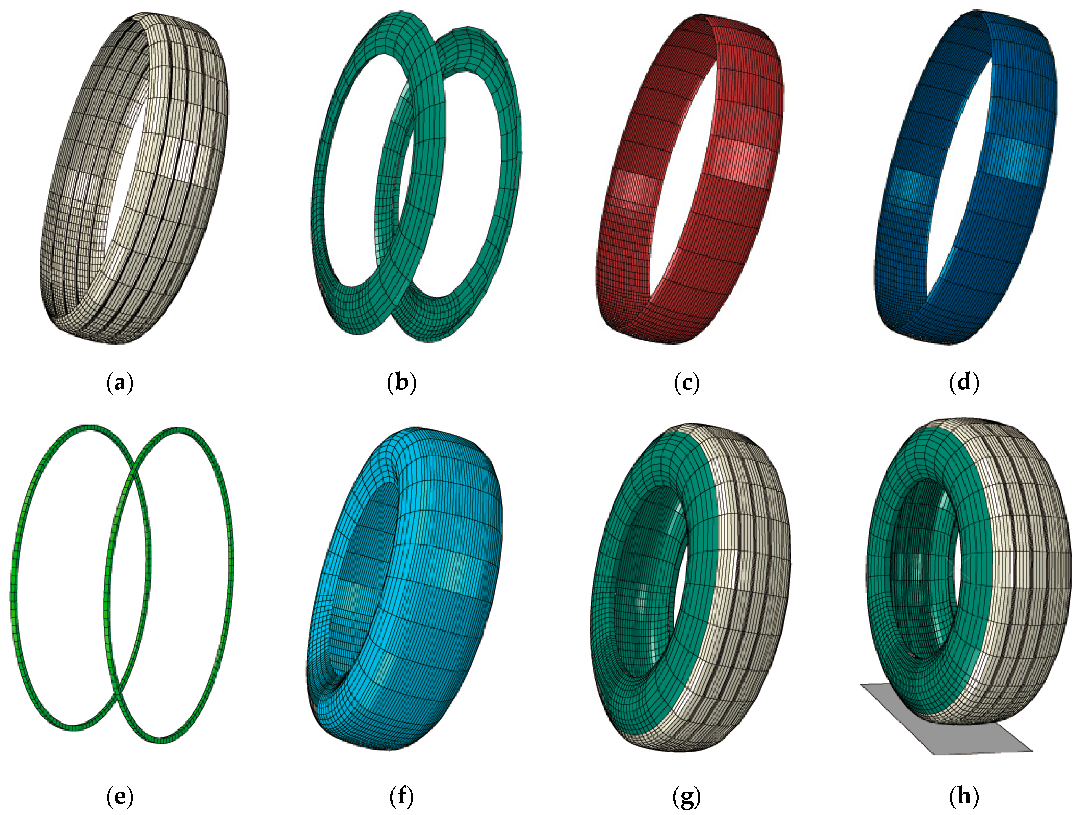
Figure 2 presents the tyre–pavement contact model and the components of a complex radial tyre (275/70R22.5), namely a truck-bus radial tyre containing four longitudinal grooves, and each tyre component is distinguished by a different colour. The outer diameter is 958 mm, the cross- sectional width is 276 mm, and steel-belt-1 and steel-belt-2 have orientation angles of 20°and −20°, respectively. The length of the mesh is 16 mm, and the width is 9 mm in the contact area. Steel- belt-1 and steel-belt-2 are located approximately 15 and 17 mm away from the outer surface of the tread, respectively. To optimise computational efficiency and ensure better convergence, the tread of the tyre in contact with the road surface is selected as a dense mesh, and the other non-contact locations of the tyre are selected as a sparse mesh. The material parameters of the tyre composition are based on the authors’ previous study [34].

2.4. Modelling Tyre-Pavement Contact

Complex, non-linear contact problems must be considered in the study of tyre–pavement contact. There are many factors that prevent successful modelling of tyre–pavement contact; for example, some challenges that arise when modelling with a two-solid mode include the non-linear contact characteristics of the tyre–pavement, material characteristics of the tyre, fast moving conditions, great deformation of the tyre, and the nonlinear frictional relationship between the friction coefficient and velocity [35]. It is clear that dealing with the tyre–pavement problem with a two-solid mode is not sufficient. In this study, when the tyre was in contact with the road surface, the degree of the deflection of the tyre was much larger than that of the pavement. It can be presumed that the pavement is a non-deformable rigid surface to achieve better astringency and stability, and the accuracy and reliability of contact stresses analysis can still be guaranteed. In previous research, the pavement has been considered as a rigid surface that can successfully capture contact stresses [22,36,37,38]. The 3D model of tyre–pavement contact is shown in Figure 2h.

2.5. Validation of the 3D Contact Model

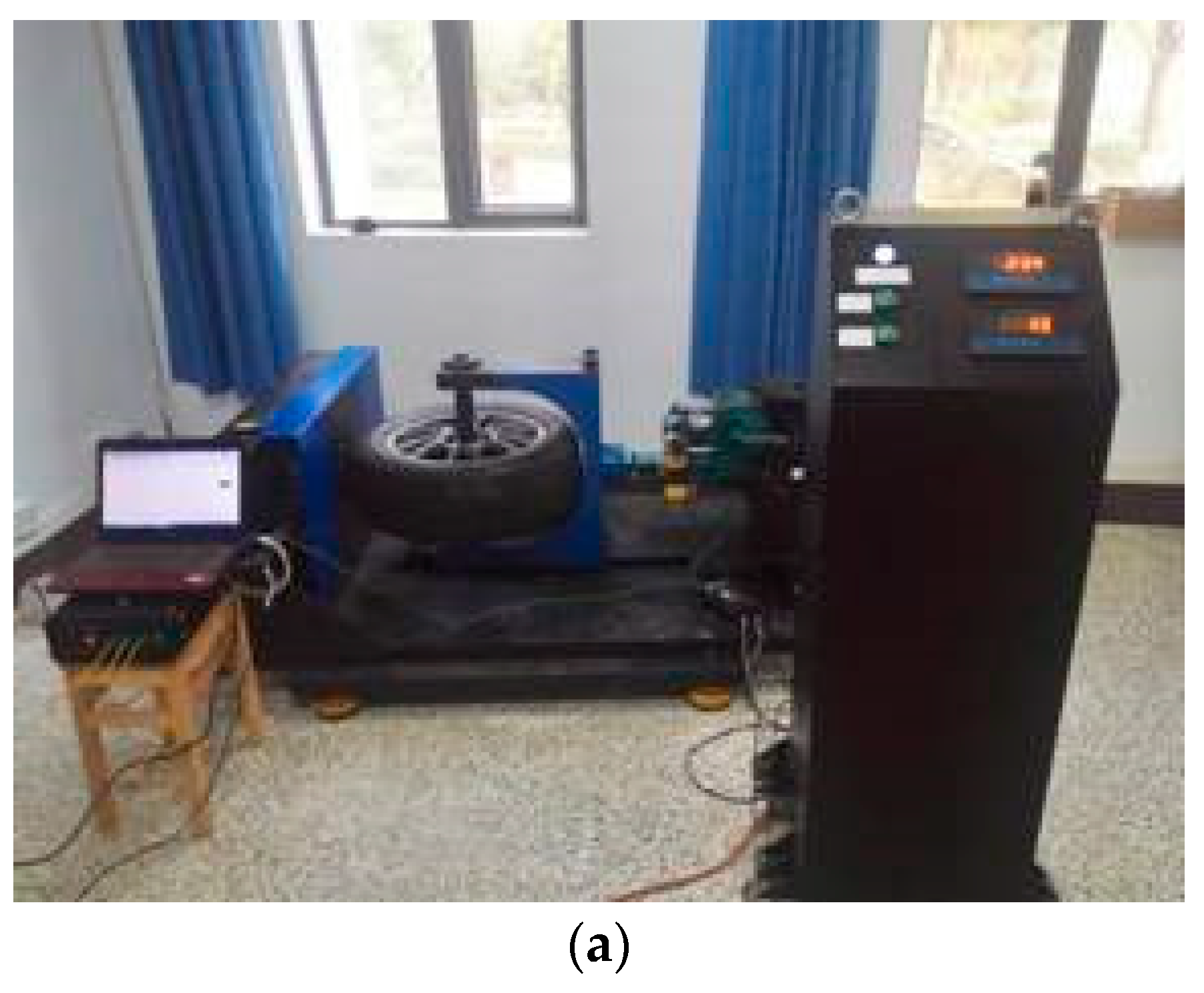
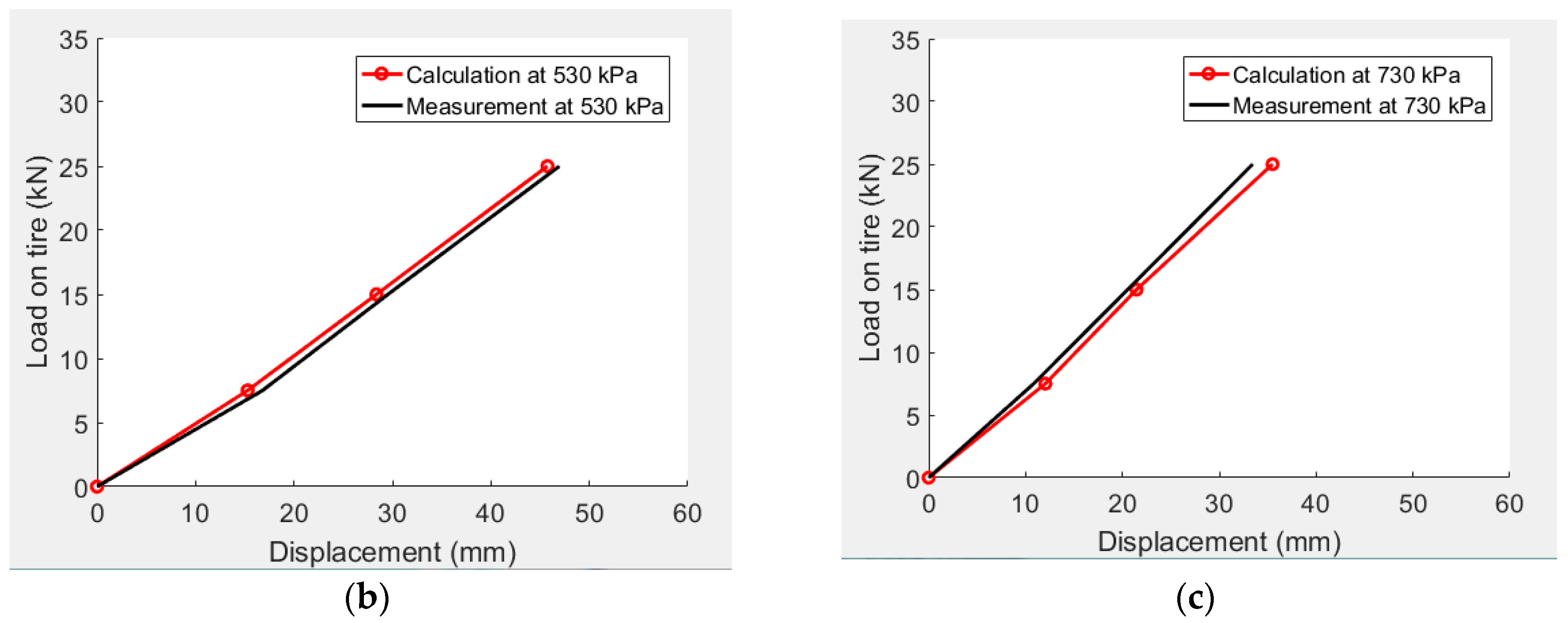
The tyre–pavement interaction model can be validated by the tyre load–displacement relationship in a static condition. Figure 3 presents the calculation comparisons of tyre deflections at a tyre load of 25 kN and different inflation pressures. When the tyre load was constant, the lower the tyre inflation pressure, the greater the displacement. The tyre loaded measurement system is presented in Figure 4a and was used to measure the deformation data of tyres with different loads. Figure 4b shows comparisons between calculated and measured tyre displacements at different tyre loads and an inflation pressure of 530 kPa. When the inflation pressure was constant, the larger the tyre load, the larger the displacement. Figure 4c shows comparisons at different tyre loads and an inflation pressure of 730 kPa. Figure 4 reveals that good consistency was achieved between the calculated and tested displacements at various tyre loads and inflation pressures.

3. Effects of Tyre Working Conditions on Contact Stresses

3.1. Simulation Condition Design of Tyre–Pavement Contact

For a two-wheel group, an axle load of 100 kN is the Chinese standard in the design of asphalt and town pavement [39]; thus, in the simulation, the vertical load (F) of each tyre was 25 kN in accordance with the standard axle load, and the vertical overloads of 30% and 60% were 32.5 and 40 kN, respectively. The rated inflation pressure (P) for a 275/70R22.5 tyre was 730 kPa [40], and the inflation pressures of 530 and 930 kPa respectively correspond to low and high inflation pressures. In addition, the friction coefficient between the tyre and road surface was 0.6 [34].

3.2. Realisation of the Steady Rolling State

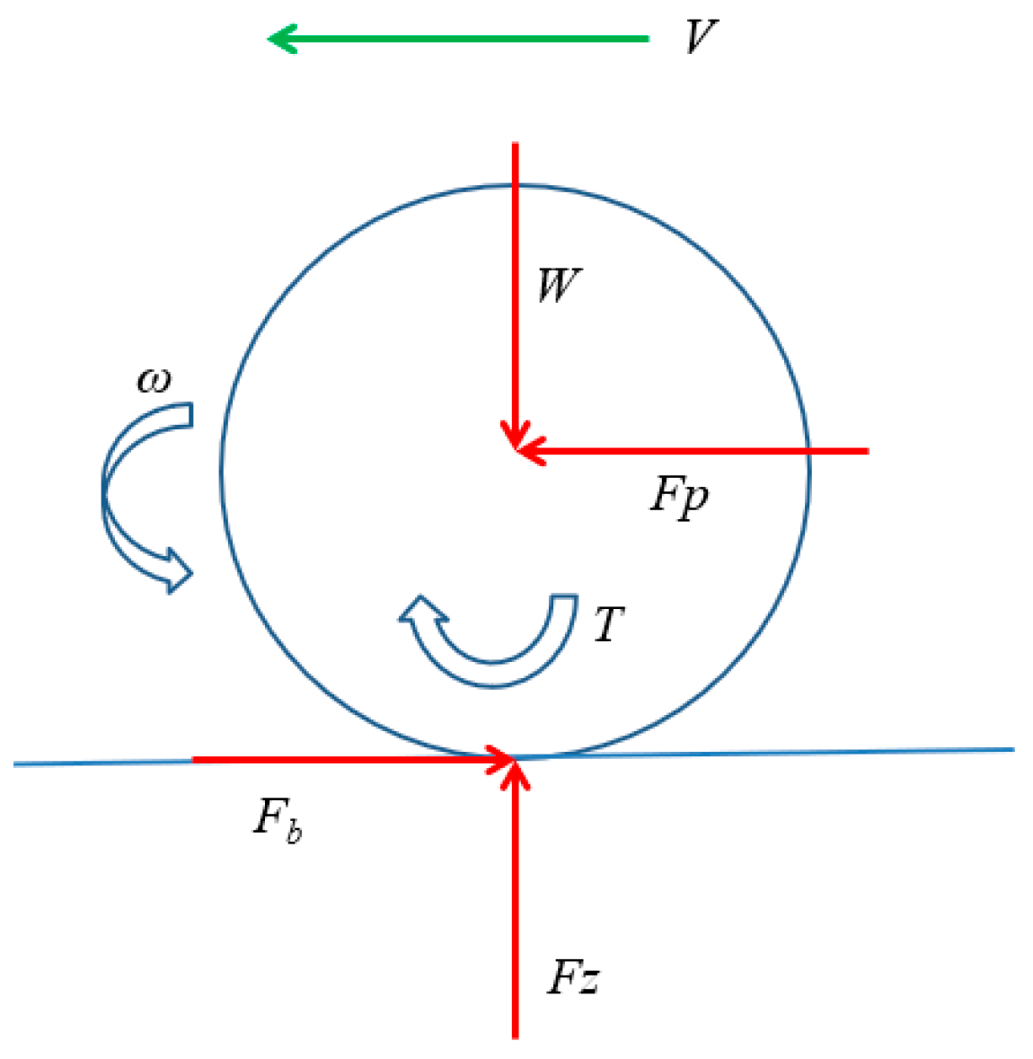
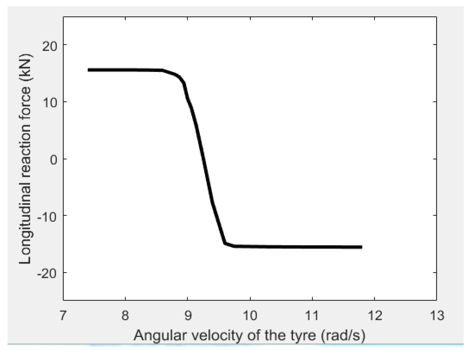
Analysis of contact stresses requires not only detailed information about tyre materials and components but also knowledge of non-linear characteristics and dynamic analysis. When the tyre is in the breaking state, the direction of braking torque (T) is opposite to the orientation of tyre rolling, as shown in Figure 5. When the tyre is in a free-rolling state, there is no braking torque. Figure 6 shows the longitudinal reaction force at different angular velocities for a linear velocity of V = 15 km/h. At the moment, the angular velocity of the free-rolling tyre corresponds to the angular velocity at zero torque. When the tyre is in the breaking state, the braking torque is transmitted to the tyre, and the angular velocity is less than that in the free-rolling condition, as shown in Figure 6. When the longitudinal reaction force has a positive value, it means that the tyre is in the braking state. When the longitudinal reaction force is basically constant, it means that the tyre is under full-braking conditions. Because the braking and acceleration forces are similar, this study focuses on comparing the change characteristics of the contact stresses and contact area with basic working conditions under free-rolling and full-braking conditions. The basic working condition was a tyre load of 25 kN, an inflation pressure of 730 kPa, and a speed of 15 km/h. Based on the described research method and results, the functional relationship between RR and tyre working conditions are explored.

3.3. Effect of Tyre Load on the Change Characteristics of Contact Stresses

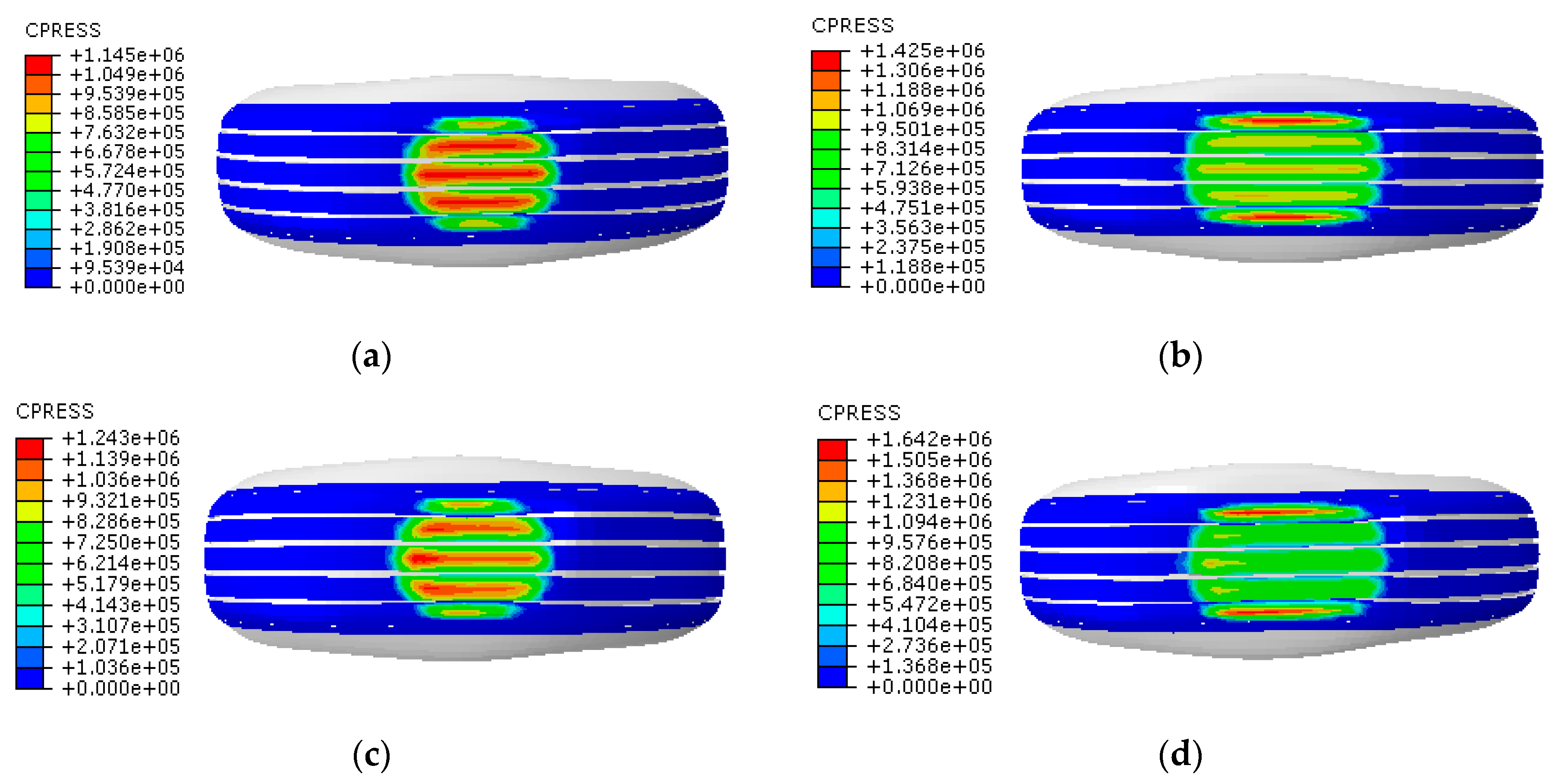
The inflation pressure of 730 kPa and a tyre speed of 15 km/h were considered to be invariant, while the tyre load was varied to examine the effect of tyre load on tyre–pavement contact stresses. Figure 7 shows the vertical contact stresses (CPRESS) under free rolling and full braking with tyre loads of 25 and 40 kN. With the gradual increase of the tyre load under the condition of steady rolling, the shape of the contact region was found to transition from approximately circular to rectangular, and the contact area also gradually increased. Regardless of whether the tyre was in the free-rolling or full-braking condition, the vertical stress at the tread of the tyre was found to change only slightly. However, the vertical stress was found to increase at the tyre shoulder. When the tyre load was small, the maximum value of vertical contact stress was near the centre of the tread, whereas when the load became large, the maximum value of vertical contact stress moved toward the tyre shoulder. Under different load conditions, the vertical stress was found to be greater under the full-braking condition than under the free-rolling condition. When the tyre load changed from 25 to 40 kN, the vertical stress of the free-rolling tyre increased from 1145 to 1425 kPa, an increase of 24.5%, while the vertical stress during full braking increased from 1243 to 1642 kPa, an increase of 32.1%. It is evident that once the overload is excessive during full braking, the maximum value of vertical stress occurring at the tyre shoulder will increase the damage to the tyre.
Figure 8 shows the longitudinal contact stresses (CSHEAR1) in the free-rolling and full-braking conditions with tyre loads of 25 and 40 kN. The shapes of the contact region under free-rolling and full-braking conditions were very different. When the longitudinal contact stress was calculated under the full-braking condition, the contact area shape and stress distribution were similar to those when the vertical stress was calculated. However, when the longitudinal contact stress was calculated under the free-rolling condition, the shape of the contact region and stress distribution varied greatly from when the vertical stress was calculated. According to Figure 8a,b, the longitudinal contact stress had positive and negative values during free rolling, and the positive and negative values were relatively close; this is mainly because the torque applied to the tyre was 0. It can be seen from Figure 8c,d that the longitudinal contact stress during full braking was positive. With the increase of load, the longitudinal contact stress gradually increased, and the position at which the maximum value of longitudinal stress occurred also moved from near the centre of the tread to the tyre shoulder, which was similar to the trend of vertical stress. As the tyre load increased, the difference between longitudinal stress during full braking and that during free rolling became increasingly larger. This illustrates that overload under in the braking condition not only does great harm to the tyre but can also accelerate the emergence of ruts and cracks in the pavement.
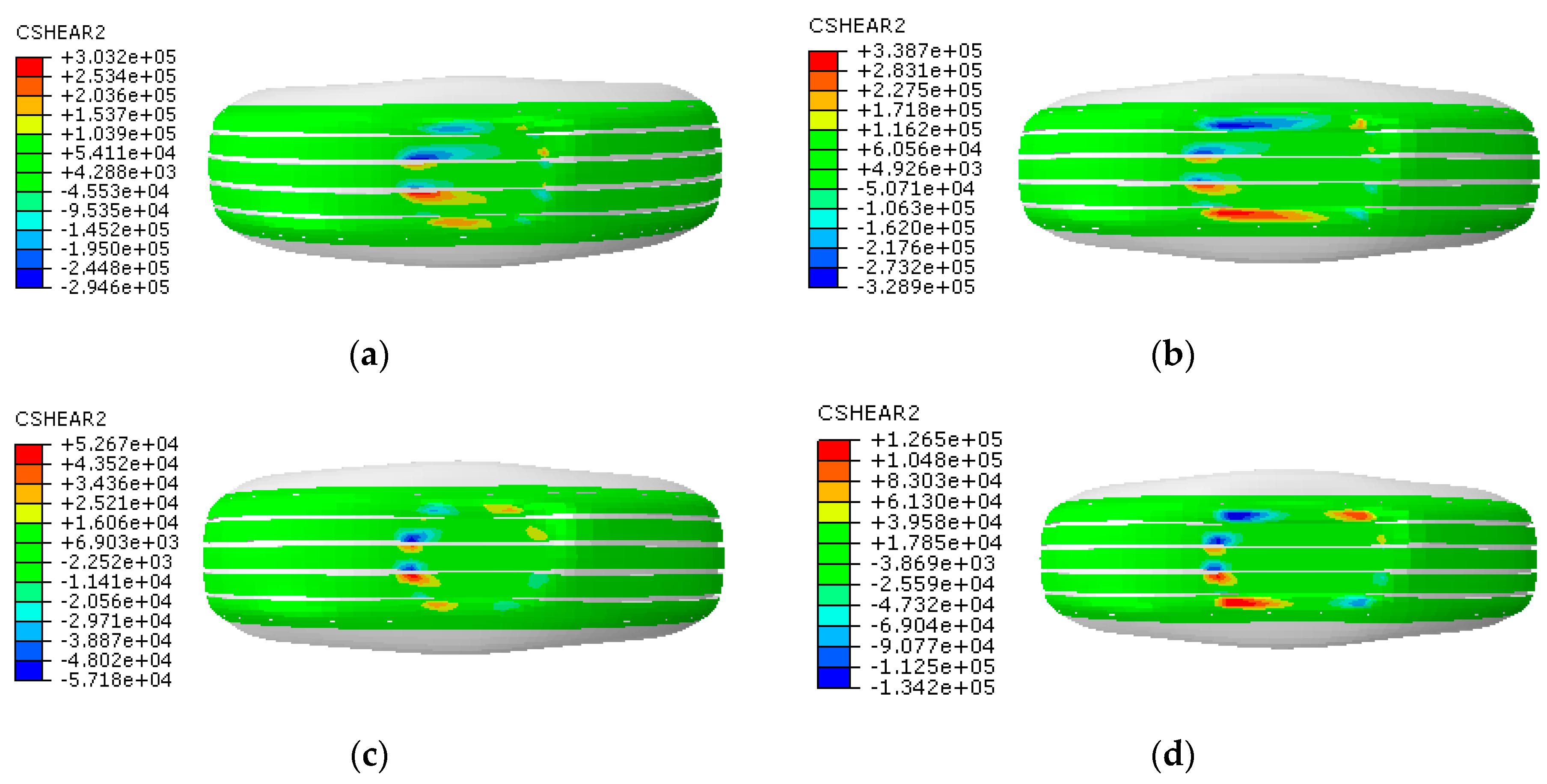
Figure 9 shows the lateral contact stresses (CSHEAR2) under free-rolling and full braking conditions with tyre loads of 25 and 40 kN. The shape of the contact region for calculating transverse stress was different from those for calculating vertical and longitudinal contact stresses under the two working conditions. Transverse contact stress had positive and negative values that were close to each other under the two working conditions. This is mainly because during the longitudinal movement process of the tyre, the tyre did not undergo sideslip, and the transverse force of the tyre was close to the equilibrium state. When the tyre load was 25 kN, the lateral contact stress during free rolling was greater than that during full braking. When the load continued to increase, the lateral contact stresses during free rolling and full braking were closer, and the difference between them became smaller.
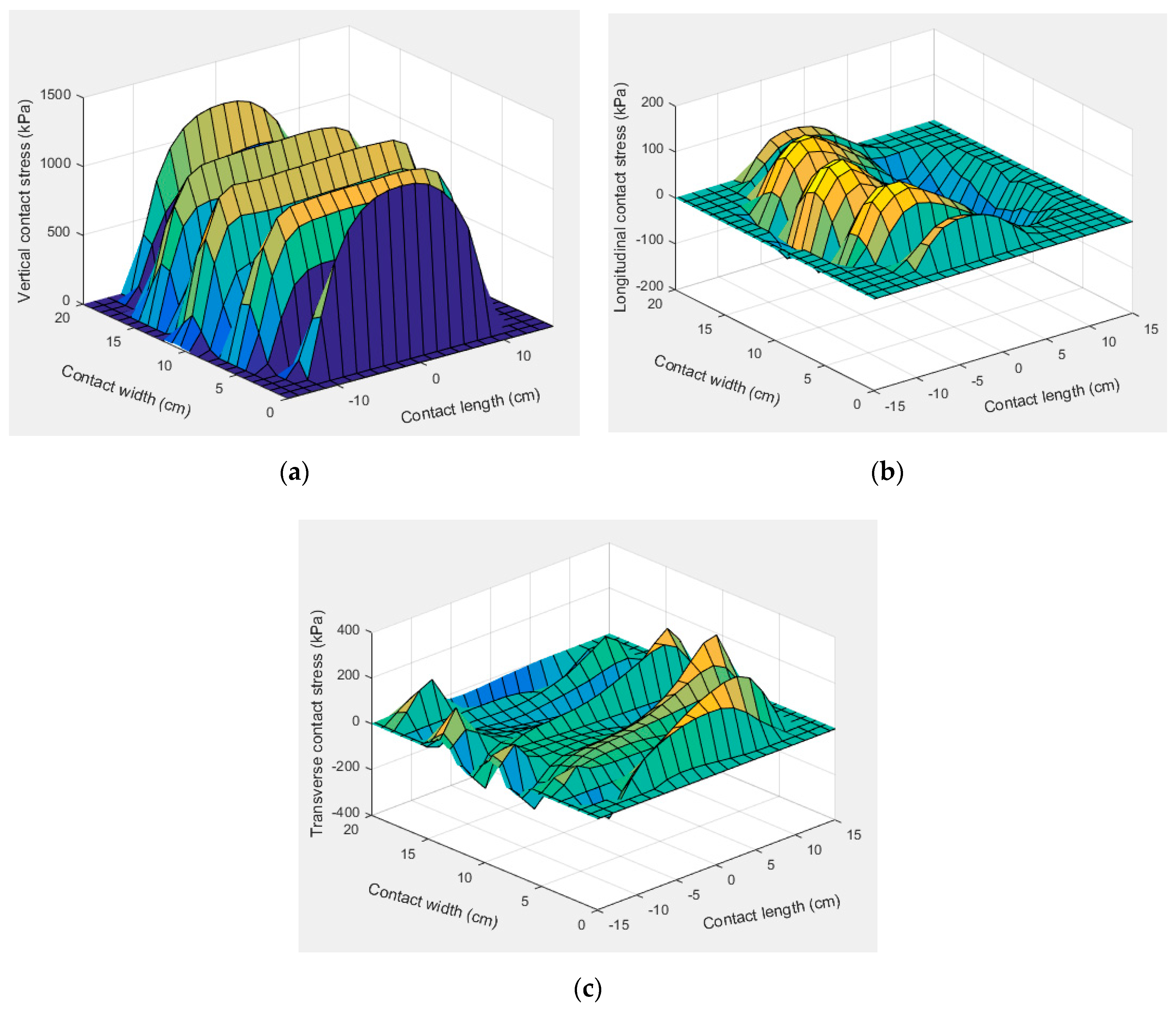
Taking the tyre load of 32.5 kN as an example, the spatial distribution of contact stresses under the free-rolling condition is shown in Figure 10. As presented in Figure 10b, longitudinal contact stress under the free-rolling condition was symmetrically distributed in a longitudinal direction, whereas, as presented in Figure 10c, the lateral contact stress exhibited an almost antisymmetric distribution in a longitudinal direction. The longitudinal contact stress was negative at the front end of the contact area and positive at the back end, and the distribution area of the negative value of the contact area was smaller than that of the positive value.

3.4. Effect of Inflation Pressure on the Change Characteristics of Contact Stresses

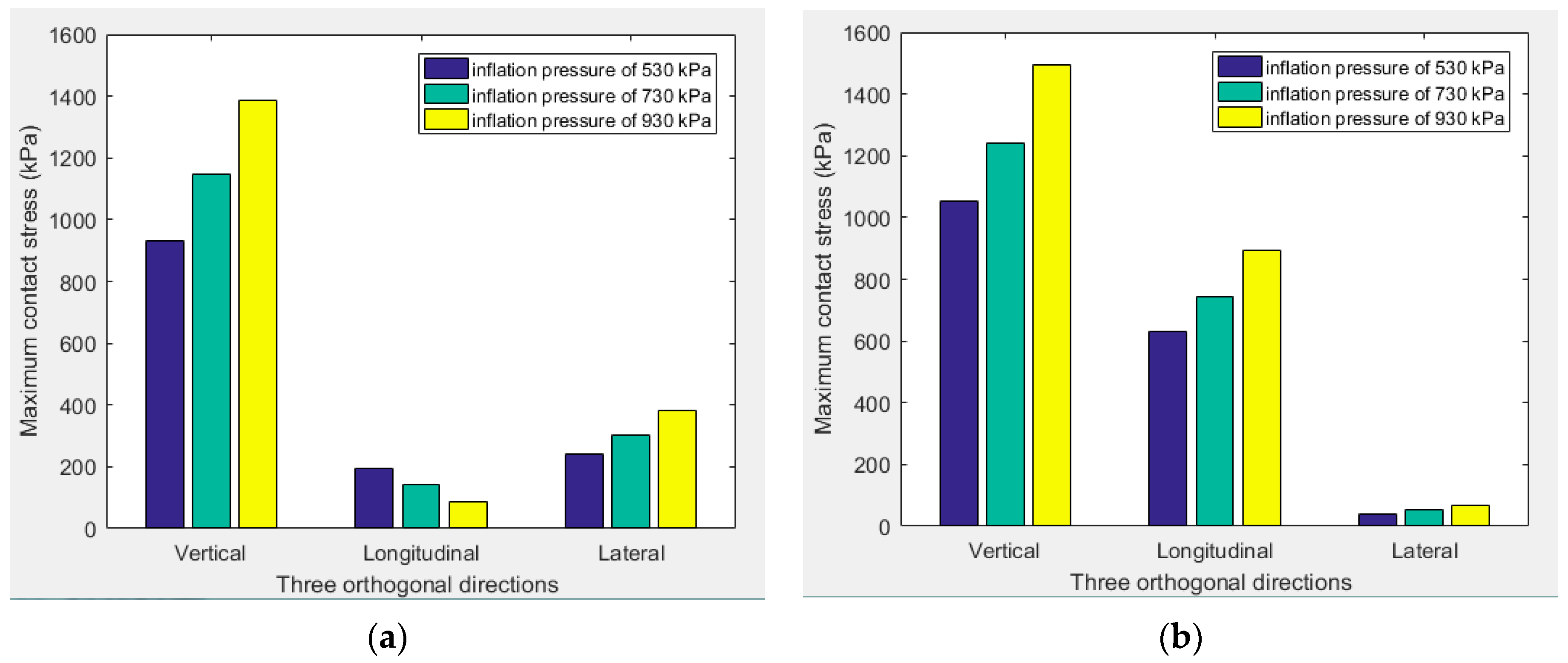
The tyre load of 25 kN and the speed of 15 km/h were considered to be invariant, while the inflation pressure was varied to examine the effect of inflation pressure on tyre–pavement contact stresses. Table 1 presents maximum contact stresses under different inflation pressures under free-rolling and full-braking conditions.
As the tyre inflation pressure was increased, the contact area decreased, and the vertical stress increased. Regardless of whether the tyres were in the free-rolling or full-braking condition, the vertical stress was positive, indicating that the direction of stress was downward. It also indicates that the tyre tread was compressed and therefore bore compressive stress. To clearly observe the change trend, Figure 11 exhibits maximum contact stresses under different inflation pressures in the form of a colour histogram.
When the inflation pressure was 530 kPa, the maximum vertical stress was located in the tyre shoulder. As the inflation pressure increased from 730 to 930 kPa, the maximum vertical stress under the free-rolling condition increased from 1145 to 1386 kPa, an increase of 21.0%. The maximum vertical stress under the full-braking condition increased from 1243 to 1495 kPa, an increase of 20.3%, and the position of the maximum values moved from the tyre shoulder to the crown. Under different inflation pressures, the contact area during the free-rolling condition was similar for different tyre loads. When the inflation pressure was high, the magnitude of the positive value of longitudinal stress was slightly less than that of the negative value. With the increase of inflation pressure, longitudinal stress decreased, and lateral stress increased. Under the full-braking condition, the lateral stress also increased with the increase in tyre pressure, but it was not obvious.
Taking the tyre pressure of 930 kPa as an example, the contact stress value of the node in the contact area under the full-braking condition was extracted, and the spatial distribution characteristics of the complex contact stresses under a high tyre pressure are exhibited in Figure 12. The vertical stress under a high tyre pressure was greater than that under the basic working condition, and the spatial distribution was large in the middle and small on both sides. Longitudinal contact stresses under the full-braking condition were symmetrically distributed in a longitudinal direction, while the lateral contact stress presented an almost antisymmetric distribution in a longitudinal direction. In addition, the front end of the vertical and longitudinal stresses was greater than the back end, which was determined by the motion state of the tyre. Overall, the lateral contact stress was less than 100 kPa and therefore could almost be ignored.

3.5. Effect of the Tyre Speed on the Change Characteristics of Contact Stresses

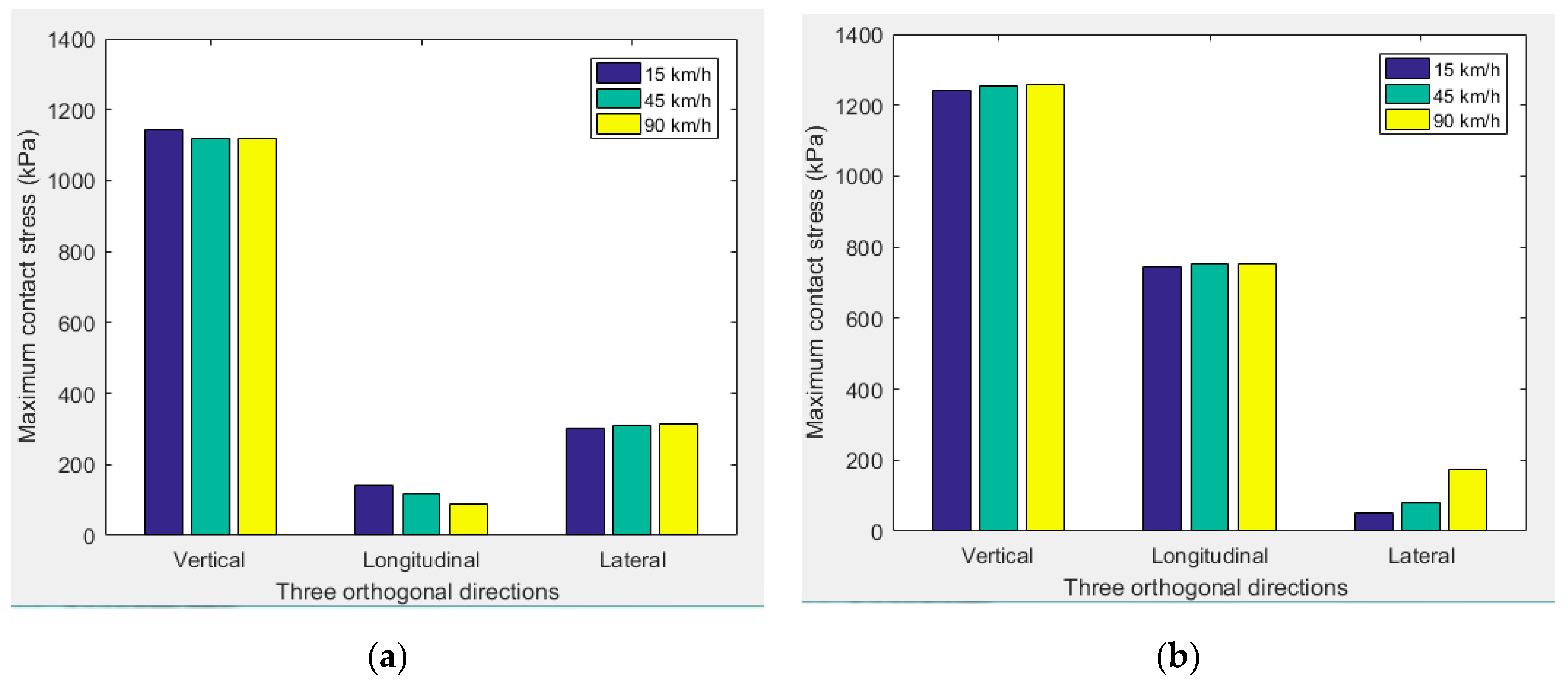
The tyre load of 25 kN and the inflation pressure of 730 kPa were considered to be invariant, while the speed was varied to examine the effect of speed on tyre–pavement contact stresses. Table 2 presents the maximum contact stresses under different speeds during free rolling and full braking. To clearly observe the change characteristics, Figure 13 shows the maximum contact stresses under different inflation pressures, in the form of a colour histogram. As the speed increased, the vertical and longitudinal stresses gradually decreased under the free-rolling condition, but the reduction was very small. The lateral stress remained essentially unchanged. Under the full-braking condition, vertical stress increased slightly. The longitudinal stress remained basically unchanged, and the transverse stress gradually increased, but the value of transverse stress was negligible compared with the value of vertical stress. Compared with the tyre load and inflation pressure, the impact of tyre speed on the maximum contact stresses is relatively weak.

4. Effects of Tyre Working Conditions on Rolling Resistance

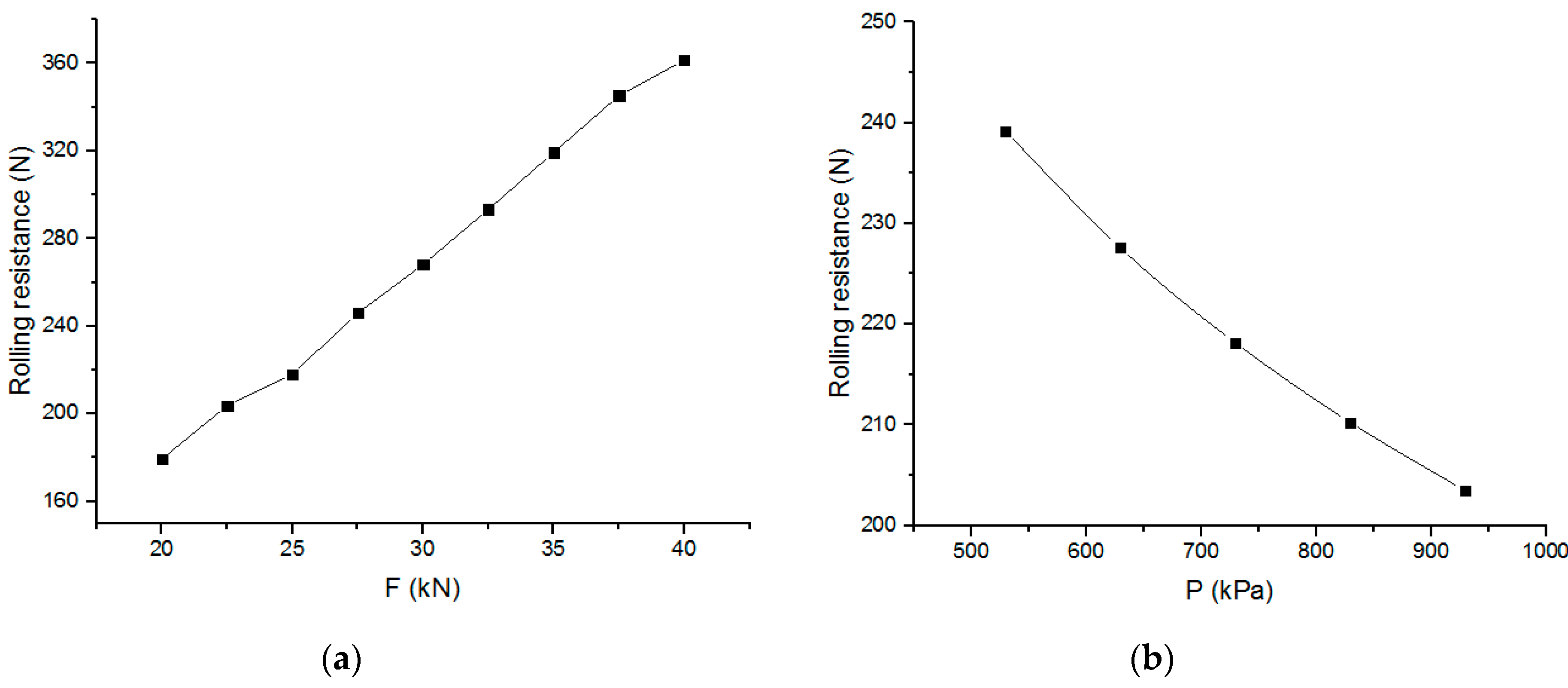
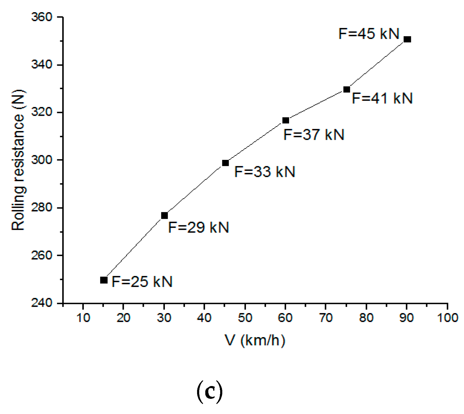
Due to the viscoelasticity of tyre rubber material, the processes of compression and rebound are not the same in the rolling process, and therefore the sum of external forces on the tyre i.e., the RR, is not 0 [41]. Figure 14 presents changes in RR with the tyre load, inflation pressure, and speed. Figure 14a shows the change in RR with the tyre load when the inflation pressure (P) was 730 kPa, and the speed (V) was 45 km/h. With the increase in tyre load, tyre deformation increased significantly, and the overall RR presented an upward trend, which would cause the vehicle to consume more fuel. Figure 14b shows the change in RR with the pressure when the tyre load (F) was 25 kN and the speed (V) was 45 km/h. With the increase in pressure, tyre stiffness increased, and deformation decreased under the same load; thus, the overall RR presented a downward trend, which would result in the vehicle consuming less fuel. Figure 14c shows the change in RR with the tyre load and speed when the pressure (P) was 730 kPa, and it was found that the increased tyre load led to increased RR. Moreover, as the speed increased, the loss factor of tyre rolling and deformation decreased [42]. However, the increased value of RR was greater than the decreased value, so the overall RR still increased.
The exponential Equation (8) is used to fit the functional relationship between RR and tyre load, inflation pressure, and speed parameters, and variable combinations were considered, as shown in Figure 14. The exponential equation is as follows:
R R = ( a + b · V + c · V 2 ) · F m · P n
where a, b, and c are velocity correlation coefficients, m is the tyre load exponent, and n is the inflation pressure exponent. According to these sets of variable combinations, the following relationship is obtained by fitting the functional relationship:
R R = ( 0.13153 0.00211 · V + 0.00001 · V 2 ) · F 1.13258 · P 0.28753
The international standard unit was adopted for the unit of each parameter in the process of fitting. The parameters in Equation (9) are different for different types of tyres, but Equation (9) describes a method that can calculate the RR related to tyre working conditions. The tyre studied in this article is one of the most commonly used truck-bus tyres in China. Therefore, Equation (9) can be used to forecast the RR of the tyre studied in this article in any combination of working conditions, and a similar method can be used to forecast the RRs of other types of tyres.

5. Conclusions

The tyre-pavement contact model developed in this work shows the potential to predict contact stresses and rolling resistance under different rolling conditions. Based on the preceding analysis, the following conclusions can be made and provide valuable suggestions and viewpoints for tyre–pavement contact mechanics and fuel-economic tyre production/design.
(1)
The maximum value of the transverse contact stress is greater than the longitudinal contact stress under the free-rolling condition. However, the situation under the full-braking condition is the opposite.
(2)
Longitudinal contact stresses under the free-rolling and full-braking conditions were symmetrically distributed in a longitudinal direction, while the lateral contact stress presented an almost antisymmetric distribution in a longitudinal direction. Under the full-braking condition, longitudinal stress is the main component of the horizontal contact stresses.
(3)
The tyre load and inflation pressure have significant impacts on contact stresses. Overload and low tyre pressure are important contributors to the wear of the tyre shoulder. Properly increasing the inflation pressure can effectively relieve damage to the tyre shoulder caused by overloading. Additionally, compared with the tyre load and inflation pressure, the impact of tyre speed on contact stress is relatively weak.
(4)
The proposed exponential equation describes a method that can forecast the RR related to the working conditions of truck-bus tyres, and a similar method can be used to predict the RRs of other types of tyres.
It is evident from the full analysis presented in this study that the change rules of contact stresses and RR are significantly affected by tyre working conditions under different rolling conditions. Conventional methods focus on the RR of patterned tyres of passenger cars or on the adoption of special materials to reduce the RR of truck tyres. Our new approach considers the different working conditions of the tyre by investigating changes in contact stresses (forces) to pinpoint the functional relationship between the RR and working conditions of the truck-bus tyre. The proposed exponential equation method can be usefully applied to predict the RR, and better estimations of fuel consumption and greenhouse gas emissions can then be made.

Author Contributions

Conceptualization, M.G. and X.L.; methodology, M.G.; software, M.G.; validation, M.G. and X.L.; formal analysis, M.G. and X.L.; investigation, M.G. and X.L.; resources, M.G. and X.L.; data curation, M.G. and X.L.; writing—original draft preparation, M.G. and X.L.; writing—review and editing, M.R. and Y.Y.; visualization, M.R. and Y.Y.; supervision, X.Z.; project administration, M.G. and X.L.; All authors have read and agreed to the published version of the manuscript.

Funding

This research was funded by the National Major Scientific Research Instrument Development Project of China (No. 51827812), National Natural Science Foundation of China (Nos. 51778509 and 51578430).

Conflicts of Interest

The authors declare that there is no conflict of interest.

References

  1. Guan, Y.J.; Zhao, G.C.; Cheng, G. FEA and testing studies on static camber performance of the radial tire. J. Reinf. Plast. Comp. 2007, 26, 1921–1936. [Google Scholar]
  2. Guan, Y.J.; Zhao, G.C.; Cheng, G. 3-Dimensional non-linear FEM modeling and analysis of steady-rolling of radial tires. J. Reinf. Plast. Comp. 2011, 30, 229–240. [Google Scholar] [CrossRef]
  3. Park, S.; Yoo, W.; Cho, J.; Kang, B. Pressure-sensing pad test and computer simulation for the pressure distribution on the contact patch of a tyre. Proc. Inst. Mech. Eng. Part D J. Automob. Eng. 2007, 221, 25–31. [Google Scholar] [CrossRef]
  4. Wang, W.; Yan, S.; Zhao, S. Experimental verification and finite element modeling of radial truck tire under static loading. J. Reinf. Plast. Comp. 2013, 32, 490–498. [Google Scholar] [CrossRef]
  5. De Beer, M.; Fisher, C. Evaluation of non-uniform tire contact stresses on thin asphalt pavements. In Proceedings of the 9th International Conference on Asphalt Pavements, Copenhagen, Denmark, 17–22 August 2002. [Google Scholar]
  6. Elseifi, M.A.; Al-Qadi, I.L.; Yoo, P.J.; Janajreh, I. Quantification of pavement damage caused by dual and wide-base tires. Transp. Res. Rec. 2005, 1940, 125–135. [Google Scholar] [CrossRef]
  7. Al-Qadi, I.L.; Yoo, P.J. Effect of surface tangential contact stress on flexible pavement response. In Proceedings of the Journal of Association of Asphalt Paving Technologists: From the Proceedings of the Technical Sessions, San Antonio, TX, USA, 11–14 March 2007. [Google Scholar]
  8. Al-Qadi, I.L.; Wang, H.; Yoo, P.J.; Dessouky, S.H. Dynamic analysis and in-situvalidation of perpetual pavement response to vehicular loading. Transp. Res. Rec. 2008, 2087, 29–39. [Google Scholar] [CrossRef]
  9. Wang, H.; Al-Qadi, I.L. Evaluation of surface-related pavement damage due to tire braking. Road. Mater. Pavement. 2010, 11, 101–122. [Google Scholar] [CrossRef]
  10. Wang, G.; Roque, R. Three-dimensional finite element modeling of static tire–pavement interaction. Transp. Res. Rec. 2010, 2155, 158–169. [Google Scholar] [CrossRef]
  11. Wang, G.; Roque, R. Impact of wide-based tires on the near-surface pavement stress states based on three-dimensional tire-pavement interaction model. Road. Mater. Pavement. 2011, 12, 639–662. [Google Scholar] [CrossRef]
  12. Ghosh, S.; Sengupta, R.A.; Kaliske, M. Prediction of rolling resistance for truck bus radial tires with nanocomposite based tread compounds using finite element simulation. Rubber. Chem. Technol. 2014, 87, 276–290. [Google Scholar] [CrossRef]
  13. Hernandez, J.A.; Al-Qadi, I.L. Semicoupled Modeling of Interaction between Deformable Tires and Pavements. J. Transp. Eng. A Syst. 2017, 143, 1–9. [Google Scholar] [CrossRef]
  14. De Beer, M.; Fisher, C.; Jooste, F.J. Determination of pneumatic tire pavement interface contact stresses under moving loads and some effects on pavements with thin asphalt surfacing layers. In Proceedings of the 8th International Conference on Asphalt Pavements, Seattle, WA, USA, 10–14 August 1997; pp. 179–227. [Google Scholar]
  15. Assogba, O.C.; Tan, Y.; Sun, Z.; Lushinga, N.; Zheng, B. Effect of vehicle speed and overload on dynamic response of semi-rigid base asphalt pavement. Road. Mater. Pavement. 2019, 1–31. [Google Scholar] [CrossRef]
  16. Si, C.; Chen, E.; You, Z.; Zhang, R.; Qiao, P.; Feng, Y. Dynamic response of temperature-seepage-stress coupling in asphalt pavement. Constr. Build. Mater. 2019, 211, 824–836. [Google Scholar] [CrossRef]
  17. Alireza, S. Numerical comparison of flexible pavement dynamic response under different axles. Int. J. Pavement. Eng. 2016, 17, 377–387. [Google Scholar]
  18. Tarefder, R.A.; Ahmed, M.U.; Islam, M.R. Impact of cross-anisotropy on embedded sensor stress–strain and pavement damage. Eur. J. Environ. Civ. Eng. 2014, 18, 845–861. [Google Scholar] [CrossRef]
  19. Ahmed, M.U.; Rahman, A.; Islam, M.R.; Tarefder, R.A. Combined effect of asphalt concrete cross-anisotropy and temperature variation on pavement stress–strain under dynamic loading. Constr. Build. Mater. 2015, 93, 685–694. [Google Scholar] [CrossRef]
  20. Tarefder, R.A.; Ahmed, M.U.; Rahman, A. Effects of cross-anisotropy and stress-dependency of pavement layers on pavement responses under dynamic truck loading. J. Rock. Mech. Geotech. Eng. 2016, 8, 366–377. [Google Scholar] [CrossRef] [Green Version]
  21. Wang, H.; Al-Qadi, I.L.; Stanciulescu, I. Simulation of tyre–pavement interaction for predicting contact stresses at static and various rolling conditions. Int. J. Pavement Eng. 2012, 13, 310–321. [Google Scholar] [CrossRef]
  22. Wang, H.; Al-Qadi, I.L.; Stanciulescu, I. Effect of surface friction on tire-pavement contact stress during vehicle maneuvering. J. Eng. Mech. 2014, 140, 1–8. [Google Scholar] [CrossRef] [Green Version]
  23. Zhou, H.; Wang, G.; Ding, Y. Effect of Friction Model and Tire Maneuvering on Tire-Pavement Contact Stress. Adv. Mater. Sci. Eng. 2015, 2015, 1–12. [Google Scholar] [CrossRef] [Green Version]
  24. Cho, J.R.; Lee, H.W.; Jeong, W.B.; Jeong, K.M.; Kim, K.W. Finite element estimation of hysteretic loss and rolling resistance of 3-D patterned tire. Int. J. Mech. Mater. Des. 2013, 9, 355–366. [Google Scholar] [CrossRef]
  25. Aldhufairi, H.S.; Essa, K. Tire rolling-resistance computation based on material viscoelasticity representation. Adv. Automot. Eng. 2019, 2, 167–183. [Google Scholar]
  26. Rafei, M.; Ghoreishy, M.H.R.; Naderi, G. Computer simulation of tire rolling resistance using finite element method: Effect of linear and nonlinear viscoelastic models. Proc. Inst. Mech. Eng. Part D J. Automob. Eng. 2019, 233, 2746–2760. [Google Scholar] [CrossRef]
  27. Anghelache, G.; Moisescu, R.; Sorohan, S.; Buretea, D. Measuring system for investigation of tri-axial stress distribution across the tyre–road contact patch. Measurement 2011, 44, 559–568. [Google Scholar] [CrossRef]
  28. Anghelache, G.; Moisescu, R. Measurement of stress distributions in truck tyre contact patch in real rolling conditions. Vehicle. Syst. Dyn. 2012, 50, 1747–1760. [Google Scholar] [CrossRef]
  29. De Beer, M.; Fisher, C. Stress-In-Motion (SIM) system for capturing tri-axial tyre–road interaction in the contact patch. Measurement 2013, 46, 2155–2173. [Google Scholar] [CrossRef]
  30. Chen, B.; Zhang, X.; Yu, J. Impact of contact stress distribution on skid resistance of asphalt pavements. Constr. Build. Mater. 2017, 133, 330–339. [Google Scholar] [CrossRef]
  31. Knothe, K.; Wille, R.; Zastrau, B.W. Advanced contact mechanics-Road and rail. Veh. Syst. Dyn. 2001, 35, 361–407. [Google Scholar]
  32. Hurtford, S. Improving the Quality of Terrain Measurement. Master’s Thesis, Virginia Polytechnic Institute and State University, Blacksburg, VA, USA, 2009. [Google Scholar]
  33. Cho, J.R.; Lee, H.W.; Jeong, W.B.; Jeong, K.M.; Kim, K.W. Numerical estimation of rolling resistance and temperature distribution of 3-D periodic patterned tire. Int. J. Solids. Struct. 2013, 50, 86–96. [Google Scholar]
  34. Guo, M.; Zhou, X. Tire-Pavement Contact Stress Characteristics and Critical Slip Ratio at Multiple Working Conditions. Adv. Mater. Sci. Eng. 2019, 2019, 1–11. [Google Scholar] [CrossRef] [Green Version]
  35. Laursen, A.; Stanciulescu, I. An algorithm for incorporation of frictional sliding conditions within a steady state rolling framework. Commun. Numer. Methods Eng. 2006, 22, 301–318. [Google Scholar] [CrossRef]
  36. Zhang, X. Nonlinear Finite Element Modeling and Incremental Analysis of a Composite Truck Tire Structure. Ph.D. Dissertation, Concordia University, Montreal, QC, Canada, 2001. [Google Scholar]
  37. Meng, L. Truck Tire/Pavement Interaction Analysis by the Finite Element Method. Ph.D. Dissertation, Michigan State University, East Lansing, MI, USA, 2002. [Google Scholar]
  38. Ghoreishy, M.H.R.; Malekzadeh, M.; Rahimi, H. A parametric study on the steady state rolling behaviour of a steel-belted radial tyre. Iran. Polym. J. 2007, 16, 539–548. [Google Scholar]
  39. China Communications Construction Group Road and Bridge Technology Co., Ltd. Specifications for Design of Highway Asphalt Pavement: JTG D50—2017[S]; People’s Transportation Press: Beijing, China, 2017. [Google Scholar]
  40. Lv, J.; Mao, J.; Feng, Y.; Xiang, Z. Size Designation, Dimensions, Inflation Pressure and Load Capacity for Truck Tyres: GB/T 2977—2016 [S]; China National Standardization Administration: Beijing, China, 2016. [Google Scholar]
  41. Ye, J. Finite Element Simulation and Validation of All-Steel Radial Truck Tire Rolling Resistance; Tsinghua University: Beijing, China, 2007. [Google Scholar]
  42. Schuring, D.J. The Rolling Loss of Pneumatic Tires; The Firestone Tire and Rubber Company, Central Research Laboratories: Akron, OH, USA, 1980. [Google Scholar]
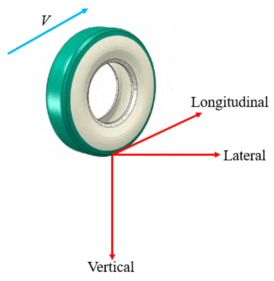
Figure 1. Three orthogonal directions of contact stresses.
Sustainability 12 10603 g001
Figure 2. Meshes of tyre components. (a) Tread with four longitudinal grooves; (b) sidewall; (c) steel-belt-1; (d) steel-belt-2; (e) bead; (f) carcass; (g) full tyre; (h) the contact model of tyre–pavement.
Sustainability 12 10603 g002
Figure 3. Comparisons of deflections at a tyre load of 25 kN and inflation pressures of (a) 530 kPa and (b) 730 kPa.
Sustainability 12 10603 g003
Figure 4. (a) Tyre static loaded test. (b) Comparisons between calculated and measured tyre displacements at different tyre loads and inflation pressures of 530 kPa and (c) 730 kPa.
Sustainability 12 10603 g004aSustainability 12 10603 g004b
Figure 5. Tyre force diagram during braking.
Sustainability 12 10603 g005
Figure 6. Longitudinal force at different angular velocities for a linear velocity of V = 15 km/h.
Sustainability 12 10603 g006
Figure 7. Vertical contact stresses under the free-rolling condition with tyre loads of (a) 25 kN and (b) 40 kN; vertical contact stresses under the full-braking condition with tyre loads of (c) 25 kN and (d) 40 kN.
Sustainability 12 10603 g007
Figure 8. Longitudinal contact stresses under the free-rolling condition with tyre loads of (a) 25 kN and (b) 40 kN; longitudinal contact stresses under the full-braking condition with tyre loads of (c) 25 kN and (d) 40 kN.
Sustainability 12 10603 g008
Figure 9. Lateral contact stresses under the free-rolling condition with tyre loads of (a) 25 kN and (b) 40 kN; lateral contact stresses under the full-braking condition with tyre loads of (c) 25 kN and (d) 40 kN.
Sustainability 12 10603 g009
Figure 10. Spatial distribution characteristics of (a) vertical, (b) longitudinal, and (c) transverse contact stresses under the free-rolling condition with the load of 32.5 kN.
Sustainability 12 10603 g010
Figure 11. Maximum contact stresses under different inflation pressures during (a) free rolling and (b) full braking.
Sustainability 12 10603 g011
Figure 12. Spatial distribution characteristics of (a) vertical, (b) longitudinal, and (c) transverse contact stresses under the full braking condition with inflation pressure of 930 kPa.
Sustainability 12 10603 g012
Figure 13. Maximum contact stresses under different speeds during (a) free rolling and (b) full braking.
Sustainability 12 10603 g013
Figure 14. Rolling resistance (RR) changes with (a) tyre load, (b) inflation pressure, and (c) tyre load and speed.
Sustainability 12 10603 g014aSustainability 12 10603 g014b
Table 1. Comparison of maximum contact stresses under different inflation pressures.
Inflation Pressure (kPa)Maximum Contact Stress during Free Rolling (kPa)Maximum Contact Stress during Full Braking (kPa)
VerticalLongitudinalLateralVerticalLongitudinalLateral
530931194240105263140
7301145142303124374552
930138686381149589666
Table 2. Comparison of maximum contact stresses under different speeds.
Speed (km/h)Maximum Contact Stress During Free Rolling (kPa)Maximum Contact Stress During Full Braking (kPa)
VerticalLongitudinalLateralVerticalLongitudinalLateral
151145142303124374552
451120116308125475282
901117873151256753175
Publisher’s Note: MDPI stays neutral with regard to jurisdictional claims in published maps and institutional affiliations.