Abstract
Cascading failures between interdependent multilayer networks are being widely studied, especially the trend of robustness caused by the interlinks between networks. However, few researchers pay attention to the effect of the interlink topology on the robustness of coupled networks, which is a critical interlink factor of multilayer networks. In this study, the method frame of multilayer network experiment simulation is given. Through numerical simulation and actual network simulation, the exhaustive method is used to enumerate all the patterns of interlink topological relations of multilayer networks (three-layer or more). The research verifies that the interlink topology affects the global robustness and that there exists a fragile interlink pattern in the patterns of interlink topologies. The star-like interlink pattern with the most uneven interlink-degree distribution leads to the weakest robustness; the pattern with average interlink-degree distribution reveals good global stability as a loop-like pattern or entire interlink pattern. In addition, the influence of interlink topology is independent. The simulation results are not affected by the network layer number and intraparameters (including the network-generated form, each layer of network node number, and average degree of each layer of network). Thus, ignoring the interlink topology may result in the actual system suddenly becoming vulnerable before the theoretical calculation point. Interlink topology as an independent factor affecting the robustness of multilayer networks should be paid more attention.
1. Introduction
The majority of real networks are not isolated but exist in an interconnected complex network. In recent years, owing to the continuous development of related internet technology, the relationships between different types of networks have unprecedentedly become highly coupled. The synthetic interactions between interdependent networks make the networks fragile because of the failures that occur in one system and spread to other systems [1,2]. In emergencies such as natural disasters or deliberate attacks, the failure of a single network may result in the failure of the functions of other networks associated with it, and then the failure of multiple networks successively occurs, which is known as cascading failure.
Cascading failure is the key problem in multilayer complex coupling networks, which is also a common action mechanism of large-scale failures. Additionally, robustness is often used to describe the stability of a system (or multilayer coupled network). In complex networks, robustness indices are often used to capture cascading failures. When the vulnerability index changes suddenly, it indicates that the inherent properties of the network have changed suddenly, and the cascade failure phenomenon is likely to occur in the network. If cascading failures can easily occur in the coupled network, the system is said to be fragile; that is, the robustness of the system is poor. Buldyrev et al. [3] demonstrated the transmission process of seismic disruption effects on the performance of real interdependent electric power and water networks. Then, Buldyrev et al. [4,5,6] established a research framework based on the percolation theory and described the functional formalization as a two-layer coupled network, which described the robustness of the phase transition. A first-order phase transition (discontinuous phase transition) was observed, which was significantly different from the second-order phase transition (continuous phase transition) observed in isolated networks.
The interdependent networks of the real world depend on each other and usually comprise multilayer networks, such as power grid, water supply, communication, and gas networks, which are interdependent. Previous research was mainly confined to two layers of the interdependent networks; however, actual networks are comprised of more than two layers [7,8]. A study analyzed the power, water, and gas networks in Shelby County to introduce an interdependent network reconstruction design with minimal cost [9]. A vulnerability analysis was employed in modeling a railway network comprising five systems [10]. The percolation process in multilayer networks has been reported to comparatively differ from single networks [1,2]. Due to the coupling relationship between networks, the perturbation of one network may cause percolation failures of other networks.
The coupling relationship of “networks of networks” includes many categories. The widely accepted factors affecting the coupling relationship are coupled interdependencies, interlink patterns, coupled strength, corresponding relationship, interlink structure, etc., whose effects on cascade failure have been widely studied [11]. The networks with inter-similarity exhibit better robustness under random attacks [12]. The robustness increases with the degree distribution similarity of the two-layer coupled network [13]. The robustness of two-layer international trade networks increases with the in-degree and out-degree correlation. The link pattern and the matching network structure affect the robustness of coupled two-layer networks [14]. Two coupled networks with similar sizes exist in the most fragile coupling mode [15]. It is feasible to study the above factors based on a two-layer or three-layer network, and the conclusions can be extended to multilayer networks. However, it cannot reflect the effect of the interlink topology on cascading failures, because two-layer or three-layer networks do not have a complex interlink topology. Moreover, there are no studies on interdependent multilayer networks that discuss the effect of interlink topology on cascading failures. This paper attempts to discuss the interlink topology.
The interlink structure is a topological structure between the layers of coupled multilayer networks. A network of networks can assume many different interlink topologies based on the dependency between the networks. Gao et al. [16] presented the network of networks and categorized the relationship between the networks of networks into four forms, including star-like interlinks, tree-like interlinks, chain-like interlinks, and loop-like interlinks. Then, different percolation formulas were derived for the different interlink types of networks of networks [17,18]. It was found that the percolation transition of tree-like coupled networks primarily depends on the number of layers n of the interdependent networks [18,19]. Dong et al. [20,21,22] studied the classic percolation of three typical link types: star-like interlink of n Erdős–Rényi (ER), scale-free (SF), and loop-like interlink of n ER under targeted attack. Although this is a basic classification, there have been no further studies based on it. Therefore, current research can only explain that the networks of networks will lead to different overall robustness qualitatively due to the different interlayer structures. In this study, the robustness of coupled networks is analyzed by using 21 different types of network interlink topologies formed by the combination of five-layer networks. The main purpose of this study is to analyze and compare the robustness of different interlink topologies and to answer the following three questions:
- Does the interlink topology affect global robustness?
- Does a fragile interlink pattern exist in the patterns of interlink topologies?
- If there exists a fragile interlink pattern, which interlink topology is more fragile?
In this paper, Section 2 describes the experimental methods and computer simulation. Section 3 introduces the interlink topology patterns of multilayer networks. In Section 4, numerical studies are conducted on the robustness of different interlink topology patterns, the results and discussions on cascading failures are discussed, and the results are verified with a practical example. Finally, a summary and conclusions are presented in Section 5.
2. Experiments Frame
2.1. Robustness Measurement Based on Percolation Theory
It is difficult to obtain accurate analytical solutions for cascading failure processes in complex networks. The percolation theory highlights the static changes in the network topology under external effects, which is particularly suitable for evaluating the influence of topology changes between layers on system robustness. Broadbent presented the concept of percolation at the 1954 Monte Carlo conference on computational methods [23]. The percolation process refers to the process in which a medium outside the system enters the system through a certain path in a single or multiple system. It is a widespread physical phenomenon that exists both in the micro world and the macro world. Percolation theory describes the operation mechanism and characteristics of the network through physical rules and interactions. Using percolation theory to evaluate network vulnerability is essentially to record the critical value between network connectivity and disconnectivity. The penetration theory is chosen as the method to measure the robustness of the network. Newman et al. [24] demonstrated the determination of the relative size of the Giant Connected Components (GCC) of a directed graph and a statistically uncorrelated vertex. Dorogovtsev et al. [25] revealed the characteristics of the GCC of directional networks and their relative sizes.
It is assumed that only the nodes belonging to GCC are considered as normal working nodes in each network. The number of GCC nodes in the network is the index that indicates the robustness of the network [15,26]. Therefore, the size of these GCC can reflect the robustness of the multilayer network. There may be more than one giant connected component in the real network, and each connected component may change with time. In general, the giant connected component is unique. Then, the size of GCC, P∞, can be defined as
where NGCC is the number of GCC nodes, and N is the number of complete network nodes.
In general, GCC is unique in a network, but connected components can be numerous. All nodes belong to connected components which can be connected to the outside world. These nodes are occupied in the percolation process, and the probability of the existence of nodes p is called occupancy; that is, p represents the proportion of the remaining nodes:
where NCC is the number of connected component nodes.
When p = 1, all nodes in the network can be used normally; when p = 0, all nodes in the network have been destroyed. For a network, a typical percolation process is as follows. In the initial state, p = 1; that is, all nodes are occupied and can be connected as a connected component. At first, a few nodes are deleted, but the overall connectivity of the network is not affected. As more nodes are deleted, the remaining nodes cannot be connected into a connected piece, thus splitting some small connected components. As the number of small connected pieces increases, the largest connected pieces will split until the network splits. The process of the disintegration of GCC is called percolation transition, where the value of the critical point of occupancy p is called percolation threshold pc.
The cascade failure of the multilayers network can be regarded as a percolation process based on random attacks. The critical threshold of percolation pc can be used as a judgment basis for network robustness [13,27]. Assume that in each network, only the nodes belonging to GCC are considered as normal working nodes. Remove the nodes from the network according to the probability 1-p in turn in the network, then calculate the number of nodes NG contained in GCC and its size P∞. By repeating this calculation, we can obtain the proportional relationship between the size P∞ and the probability p. For a network, the removal of a node from the network means that all the edges connected to that node fail, and the connections between other nodes are broken. The network is said to be stable if, after the removal of a few nodes, most of the nodes can still be connected as a connected piece. A network is said to be vulnerable if, after removing a few nodes, it becomes difficult for most of the nodes of the network to connect together.
2.2. Experimental Parameters
2.2.1. Network Generation Function
By studying the two-layer coupling network, it has been found that the different generation methods of intralayer networks have different effects on the overall robustness. For independent networks, four typical network forms exist: regular network, Erdős–Rényi (ER) random network, Watts–Strogatz (WS) small-world network, and Barabási–Albert (B–A) scale-free network. This study refers to the results of Dong [21], which involved multilayer networks with a star structure and ring structure, and finds that the ER random network has a good level of significance in both modes. Therefore, this study adopts the ER network generation method.
2.2.2. Coupled Link Patterns
The different interlink patterns have different effects on the robustness, which has been verified by many studies [14,28]. In general, there are three types of network interlink patterns: random link (RL), assortative link (AL), and disassortative link (DL). A random link pattern indicates that the mutual links between two networks are randomly generated. Assortativity generally implies that nodes with similar properties tend to link with each other. The most common AL is one where a node with the highest degree in one network is linked with the node with the highest degree in the other network. Disassortativity is a node link between the network node and its opposite attribute node. For example, the node with the highest degree in a network is linked to the node with the lowest degree in another network.
The AL pattern indicates that a node links its own similar nodes and chooses five layers of the same network to link them in succession. The random coupling method is set to be randomly arranged, using five layers of a similar network to correspond randomly to links.
In addition, coupling strength is also a common parameter of network connection. The coupling strength q is the ratio between the number of nodes in a network that are connected to the outside world and the number of nodes in the network. In general, q is between 0 and 1. The coupling strength also affects the robustness of the coupling network. The coupling strength varies with the network in reality. However, in theoretical research, the coupling strength q = 1 is generally taken.
2.2.3. Attack Strategies
In this paper, two different attack strategies are selected, random attack and targeted attack, which are also common attack strategies to attack network nodes [29,30]. Random attacks do not take into account the importance of network nodes in the system, and targeted attacks first attack the most important node in the network. In this paper, two indexes are selected—degree centrality and betweenness centrality—which are two types of attack strategies to investigate the importance of nodes under a targeted attack. This paper does not consider the direction of the network. The degree indicates the number of edges directly connected to a node, which is the simplest but most representative index of the local importance of nodes. Betweenness is an index to investigate the shortest path passing through the node, which can better reflect the overall importance of the nodes.
Random attacks (RAs) randomly sort nodes in the network and attack them in random order. A degree-based targeted attack (DA) sorts the nodes in the network in descending order according to the degree. If some nodes in the network have the same degree, they are sorted randomly, and the nodes with the largest degree are attacked in descending order. After each attack, the nodes in the network are recalculated and arranged in descending order according to the degree of the nodes in the new network. Then, the cycle repeats. The targeted attack based on betweenness (BA) sorts the nodes in the network in descending order according to the numerical size of betweenness. If some nodes in the network have the same betweenness, they are randomly sorted, and the nodes with the largest degree are attacked in descending order. After each attack, the nodes in the network are recalculated and ranked in descending order according to the degree of the nodes in the new network. Then, the cycle repeats.
2.3. Computer Program Structure
The present section briefly describes how the modeling approach has been implemented in the computer simulation program so that it can be more readily used for robustness analyses.
The basic idea of the modeling approach is to translate the models of the interdependent networks into a computer code and implement it in a computer simulation program. In the present study, the computational procedure is written on MATLAB, as illustrated in Figure 1.
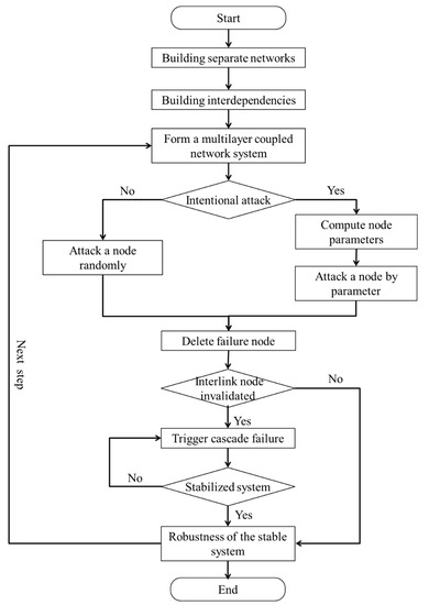
Figure 1.
Flowchart of the simulation program.
The calculation flow shown in Figure 1 is applicable to the cascading failure process of the multilayer coupled networks. The computational process can systematically assess the vulnerability of multilayer networks and take into account the interlayer dependencies. Moreover, systematic analyses are conducted from the four perspectives as described in Section 2.2, namely, robustness measures, network generation function, coupled patterns, and attack strategy. The simulation steps are as follows:
- (1)
- Establish an independent network model for each layer;
- (2)
- Establish the association relations between each layer of network (including various interlink patterns, AL or DL) so as to form the multilayer coupling network model;
- (3)
- According to the order of nodes given by the attack strategy (including DA, RA, or BA), select the failure node and delete the failure node;
- (4)
- Investigate the intralayer node cascade failure caused by the failure of this node, determine the state of the interlayer network where it is located when it is stable, and count all failed nodes;
- (5)
- Determine whether all failed nodes of this layer’s network have interlayer correlation nodes. If so, cascading failures of other layer’s network will be triggered. Once failure of the other layer’s network is triggered, step (4) needs to be repeated until no new failed nodes are found in the multilayer network to form a stable multilayer network model;
- (6)
- If there is no interlayer correlation among all the failed nodes in this layer, the failed nodes only change the structure of this layer’s network, but not the other layer’s network, so a new multilayer network model can be directly obtained;
- (7)
- Once a stable multilayer network is formed, the size P∞ of the maximum connected component and the probability p- value of node occupancy can be obtained to calculate the robustness of the multilayer network in this state;
- (8)
- Judge whether to continue the next attack. If so, repeat steps (3)-(6). If not, end the simulation.
3. Interlink Topology for Multilayer Networks
3.1. Practical Impact of Interlink Topology
Take the urban infrastructure network. The interdependent networks of the real world depend on each other and usually comprise multilayer networks, including the power grid, water supply, communication, gas network, sewage network, and other networks. Take China’s transportation network as an example, including the aviation network, train network, high-speed rail network, expressway network, primary highway network, secondary highway network, tertiary highway network, etc. Taking urban transportation network as an example, it can include the subway network, bus network, bus rapid transit network, bicycle network, public travel network and so on. So there are many different types of actual multilayer networks up to five layers or more.
Critical infrastructure networks are often intertwined and sophisticated. A recent development involved the recognition that it is often not sufficient to only understand the interlink structure. Take the cascading failure process of three infrastructure networks in a city as an example, which are interdependent on each other. In the actual case [31,32], the power grid supports the normal operation of the water supply network and gas networks, and the water supply network also supports the normal operation of the power grid. Figure 2a,b shows two different interlink topology diagrams, stacking structure, and actual directly interlink structure. Figure 2c shows the change of robustness of the multilayer network when taking interlink topology for stacking structure naturally. Figure 2d shows the robustness of the multilayer network when the interlink topology is the actual directly interlink structure, where the power grid provides power support to the gas and water networks, and the water supply layer provides water supply support to the power grid.
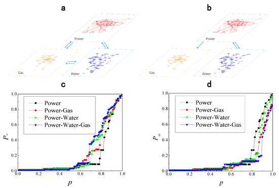
Figure 2.
A comparison case of stacking structure and actual direct dependency based on robustness. (a) Schematic of stacking structure; (b) schematic of actual directly interlink structure; (c) robustness of stacking structure; (d) robustness of actual directly interlink structure.
Figure 2c,d lists the failures of four models of power, power–gas, power–water, and power–gas–water supply under the above two interlink structure setting. In the figures, the power network (black square polyline) is a single-layer network, and the change of interlink structure will not lead to the change of its robustness, which can be regarded as a controlled experiment. Under the stacking structure model, the cascade failure of the coupled multilayer network lags behind that of the power network, indicating that the multilayer stability is better than that of the power network. Under the actual directly interlink structure model, the cascade failure of the two-layer or multilayer network was significantly earlier than that of the power network, especially the power–gas–water coupled network (blue triangular polyline), which showed the earliest second-order phase transition. This case demonstrates that the interlink topology has an impact on the robustness of the multilayer network. If we treat the gas network and water supply network as having a direct dependence in the calculation, the calculation result of system vulnerability will have a big deviation. It is because of this problem found in the actual calculation that we are curious about the interlink topology on multilayer networks.
3.2. Interlink Topology Patterns for Multilayer Networks
The interlink topology of the three-layer network case above is not complicated. With the increased number of layers, the form of the interlink topology becomes increasingly abundant. For two-layer coupled networks, only two possible interlink topology patterns (correlation and irrelevance) exist between the networks. When study is limited to interdependent networks of networks, only a dependent interlayer coupling relationship or an interdependent interlayer coupling relationship exists. If the heterogeneity of the network hierarchy is not taken into account, the two-layer coupled networks exist only in one pattern of interlink topology, namely, chain-like interlinks, and there is no need to consider the other interlink topology patterns. However, for three-layer interdependent coupled networks, two patterns of the interlink topology exist, namely, chain-like interlinks and loop-like interlinks. When the number of layers increases, the number of interlayer structure patterns increases exponentially compared with the number of layer networks. In essence, there are numerous different patterns of interlink topology. There are 68 patterns of six-layer networks, 236 of seven-layer networks and 863 of eight-layer networks. Therefore, to fully exploit the possibility of interlink topology structural relationships between networks, the interlink topology of five-layer networks is selected as the research object.
3.3. Interlink Topology Patterns for Five-Layer Networks
The network topology significantly affects the robustness of single-layer networks. A question arises as to whether the interlink topology also significantly affects the robustness of multilayer networks. Based on the previous analysis, in this paper, a five-layer network is used as the research object of the preliminary numerical experiment. As the experimental object, the interlink topology pattern of the five-layer network is neither too much nor too little. Therefore, it is suitable for research. The numerical experiment can eliminate the influence of the topological structure on the result by different intra-parameters transformation.
Figure 3 illustrates the schematic diagram of five-layer networks and several examples of possible structures. Figure 3a depicts the representative diagram of the five-layer networks from the perspective of stacking. However, it is difficult to clearly observe the interlink topology of the networks. Figure 3b,c depicts the schematic diagram of the five-layer network interlayer structure with a star-like interlink structure and loop-like interlink structure, respectively.
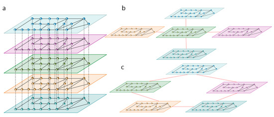
Figure 3.
Schematic diagram of the five-layer network. (a) Stacking perspective; (b) star-like interlink structure; (c) Loop-like interlinks structure.
The method of researching network topology was introduced into the study of the network interlink topology. A model comprising five interdependent networks was established, and the model was subjected to the following restrictions:
- Heterogeneity was not considered, that is, each network of nodes was considered to belong to the same network category.
- The number of network nodes in each layer was the same, building a one-to-one correspondence of interdependent networks.
- Full-meshed connections between networks: there was no independent network.
- The interlink relationship between networks was commutative: if network A depends on network B, then network B will also depend on network A.
- The no-feedback condition was satisfied [16]: the interlink relationship between networks was determined, which implies that if network A depends on network B, then node Ai of the network A must be related to node Bi of network B and vice versa.
In a structure comprising five layers of networks, there are 34 patterns of interlink topology [33], including the independent networks, without considering the full-meshed connections between networks. The five-layer incompletely connected network will degenerate into a network with fewer layers, which is beyond the scope of the study. What we want to know more, however, is the overall nature of the five networks all connected. So we just need to look at the types of networks that are all connected. If there are five interdependent networks, 21 interlink topology patterns exist. To illustrate the influence of the interlink topology on the robustness of interdependent multilayer networks, in this study, 21 patterns of different five-layer network connection modes are compared, as summarized in Table 1. Table 1 presents the interlink topology patterns where a network is replaced by a node and the distribution values of the interlink-degree.

Table 1.
Twenty-one types of interlink topologies in five layers of interdependent networks.
4. Results and Discussion
4.1. Simulation Results
In this simulation, an ER random network with a degree of 4 was selected. There were 1000 nodes on each layer of the network. The coupling strength between the network layers was q = 1. The simulation compared the two interlink patterns, which were the RL and the AL, as well as three attack strategies: RA, DA, and BA. The robustness of the coupled multilayer network was obtained, as depicted in Figure 4.
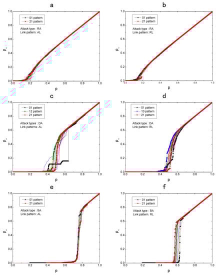
Figure 4.
System robustness of a five-layer coupling network in different interlayer topologies. Twenty-one types of interlink topologies linked with assortative link (AL) or random link (RL) under random attack (RA), degree-based targetted attack (DA), and targeted attack based on betweenness (BA). The critical types are marked. (a) Attack type RA & link pattern AL; (b) Attack type RA & link pattern RL; (c) Attack type DA & link pattern AL; (d) Attack type DA & link pattern RL; (e) Attack type BA & link pattern AL; (f) Attack type BA & link pattern RL.
As depicted in Figure 4, in the six graphs, the coupled network robustness of ER multilayer networks with AL or RL under RA, DA, and BA, respectively, was studied. Each graph contains 21 curves, and each curve demonstrates the robustness of an interlink structure pattern. The larger the p-value corresponding to the point of the first-order phase transition of the curve, the more fragile the interlink pattern corresponding to the curve. From the above results, the following conclusions can be obtained.
On the one hand, compared to the attack strategy, the influence of interlink topology on robustness is not very significant. Under different attack strategies, the robustness of the system is ranked as RA > DA > BA. Two link patterns are studied here, namely, RL and AL. From the comparison of the graphs, it can be found that the robustness of the coupled multilayer network in the AL pattern is worse than that in the RL pattern, especially in terms of the degree attack and betweenness attack. These results are consistent with the results of two-layer coupling networks [14].
However, the influence of the network interlink topology pattern on network robustness is obviously different due to the change in the attack strategy.
First, interlink topology structure patterns have very little influence on network robustness under random attacks. It can be found in Figure 4a,b that the cascade failure process does not change significantly. This is mainly because random attacks do not easily cause cascading failures. The network changes very little after each attack. Under RA, the robustness of multilayer networks is highly consistent, and only a small range of fluctuations occurs when P∞ approaches 0. This is mainly due to the characteristics of RA, which do not damage the overall network structure. Therefore, the change in interlink topology does not affect the robustness of multilayer networks.
Second, different interlink topology structure patterns exhibit significant differences in DA. In general, the failure process caused by DA is neither too fast nor too slow. Hence, the DA can better reflect the cascading failure process of the network. It can also better highlight the different failure effects of the different interlink topology modes. In other words, the failure process curve is similar. The main difference is the order in which it happens. Therefore, we can say qualitatively that the change of interlink topology does not affect the natural robustness of the system.
It can be clearly seen from Figure 4c,d that the interlink topology can speed up or slow down the system’s failure process. The specific performance is percolation threshold pc of the increase or decrease, indicating that the network robustness corresponding to the 21 patterns is different. The robustness of the multilayer network in 01 pattern is the worst, whereas the robustness of the 10 or 12 pattern is better. This may be attributed to the high concentration of interlink degree in the 01 pattern. In the degree attack strategy, the layer with the highest interlink degree of the network becomes the target layer. Once the network of this layer collapses, the system rapidly collapses. Especially in Figure 4d, there is an obvious first-order phase transition. This is because the intralayer and the interlayer topologies both have a high concentration of degree distribution. Therefore, the targeting of this attack is even more significant. Similarly, for a 10 or 12 pattern of multilayer networks, the interlayer degree distribution of the network is relatively average, and thus, the correlation of these two patterns ensures that the multilayer networks have better robustness.
Finally, there are significant differences in BA. In the AL mode, the destruction of multilayer networks occurs faster and in a more concentrated manner, resulting in no obvious difference. However, in the RL mode, the cascading failure process of the multilayer networks has a clear correlation with the network interlink topology. From Figure 4e,f, it can be found that the robustness of the multilayer networks in the 01 pattern is the worst, whereas the robustness of the 21 pattern is the best, and the difference between each mode is obvious. This is mainly because the interlinks in the 01 pattern are less and centralized, and the interlinks in the 21 pattern are more and average. Therefore, the 01 pattern (star-like interlinks) leads to poor robustness, whereas the 21 pattern (entire interlinks) leads to improved robustness. The star-like interlink structure and entire interlink structure represent two boundary conditions of the interlink topology in this case.
4.2. Parameter Analysis
In the above simulation experiment, the simulation test is conducted with the given intra-parameters (including the network generated form, each layer of network node number N, and average degree of each layer of network k). However, the question arises as to whether the simulation results will be affected by these intra-parameters and whether the fragile pattern in the patterns of interlink topologies will be affected by number of network layer. This section investigates the universality of the influence of the interlink topology structure and compares the network-generated form, number of network layer L, each layer of network node number N, and average degree of each layer of network k.
As space is limited, only two typical patterns have been listed in this section: DA with AL pattern and BA with RL pattern, respectively. As can be seen from the results in Section 4.1, different interlink topologies have significant results under these two conditions.
4.2.1. Network Generation Form
In general, for networks, there are three typical network-generation forms: ER random network, WS small-world network, and B–A scale-free network. The effect of network generation form on global robustness is also verified by the study of two-layer coupled networks. The three network generation forms are simulated, as depicted in Figure 5.
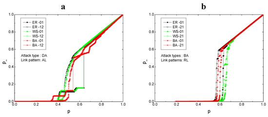
Figure 5.
Influence of interlink topology patterns on system robustness under different network generation forms. (a) Critical types (01 pattern and 12 pattern) are selected from the 21 types of five-layer coupled networks linked with the assortative link under the degree-targeted attack strategy; (b) critical types (01 pattern and 21 pattern) are selected from the 21 types of five-layer coupled networks linked with the random link under the betweenness-targeted attack strategy. The number of network layers L = 5, each layer of network node number N = 1000, and the average degree of each layer k = 4.
As can be seen from Figure 5, the interlink topologies have different effects on the system robustness under different network generation forms. The WS and BA networks (the green and red lines in the figure) have trace distributions under different interlink topology patterns; the differences between their robustness are insignificant. Moreover, the second-order phase transition of the ER network changes most significantly (the black lines in the figure). The ER network is used to study the interlayer characteristics of the network, and the distinguishing effect is more obvious, which is consistent with the results of Dong [21].
4.2.2. Number of Network Layers
Whether the influence of interlink topology patterns on network robustness has similar results under various network layers is a question of great concern. Because an interlink topology less than or equal to the three-layer network cannot generate the star-like interlink structure, the four-, five-, six-, and eight-layer networks are selected as the research objects in this case, as depicted in Figure 6.
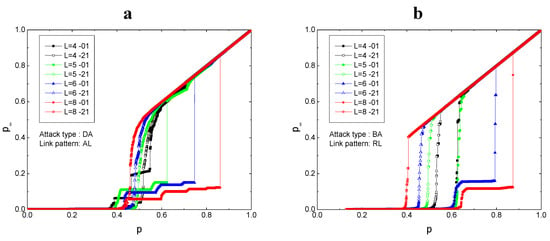
Figure 6.
Influence of interlink topology patterns on system robustness under different numbers of layers. (a) 01 and 21 patterns are selected from the 21 types of five-layer coupled networks linked with the assortative link under the degree-targeted attack strategy; (b) 01 and 21 patterns are selected from the 21 types of five-layer coupled networks linked with the random link under the betweenness-targeted attack strategy. The network generated form is Erdős–Rényi (ER), each layer of network node number N = 1000, and the average degree of each layer k = 4.
As can be seen from Figure 6, with the increase in the number of network layers, the differences between the network modes are enlarged. In Figure 6a, the networks under DA and AL demonstrate extremely poor robustness in the 01 pattern but exhibit good robustness in the 21 pattern. As the number of layers decreases, this difference gradually reduces. The differences between the four layers are not very obvious, which may also be the reason why previous studies ignored the influence of interlink topology on global robustness. It can be seen from Figure 6b that the threshold value of global robustness changes under BA and RL; however, the two interlink topology patterns corresponding to this threshold are both 01 and 21 patterns. Similarly, the more layers there are, the more significant the differences between the thresholds are. In other words, although the change in the network layer number leads to a change in the robustness, it does not affect the influence of the interlink topology patterns on system robustness.
4.2.3. Node Number of Intralayer Network
Changes in the number of nodes per layer of the network may cause global changes; hence, the possible impact of the number of nodes on the network may be examined. Figure 7 considers the number of nodes per layer of the network as 500, 1000, 2000, and 4000.
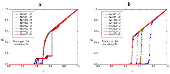
Figure 7.
Influence of interlink topology patterns on system robustness under different numbers of intralayer network nodes. (a) The critical types (01 pattern and 12 pattern) are selected from the 21 types of five-layer coupled networks linked with the assortative link under the degree-targeted attack strategy; (b) the critical types (01 pattern and 21 pattern) are selected from the 21 types of five-layer coupled networks linked with the random link under the betweenness-targeted attack strategy. The generated network form is ER, the number of network layers L = 5, and the average degree of each layer k = 4.
It can be observed from Figure 7 that the number of nodes has no influence on the vulnerability of the interlink topology patterns. In Figure 7a, the global robustness does not change with the number of nodes under DA and AL. It can be seen from Figure 7b that the threshold value of global robustness changes under BA and RL; however, the two interlink topology patterns corresponding to this threshold value are both patterns 01 and 21. Although the change in the number of network nodes leads to a change in the system robustness, it barely affects the influence of the interlink topology on system robustness.
4.2.4. Average Degree of Intralayer Network
Different averages of network lead to different network properties. Will the change in intralayer network properties affect the global robustness of interlink topology? The influence of interlink topology on system robustness under different intralayer network averages is analyzed in Figure 8.
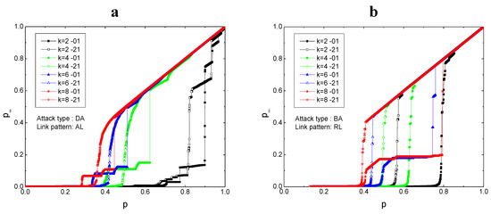
Figure 8.
Influence of interlink topology patterns on system robustness under different average degrees of each intra-layer network. (a) The critical types (01 pattern and 12 pattern) are selected from the 21 types of five-layer coupled networks linked with the assortative link under the degree-targeted attack strategy; (b) the critical types (01 pattern and 21 pattern) are selected from the 21 types of five-layer coupled networks linked with the random link under the betweenness-targeted attack strategy. The generated network form is ER, the number of network layer L = 5, and each layer of network node number N = 1000.
It can be observed from Figure 8 that the network average has no influence on the vulnerability of the interlink topology patterns, and the threshold value of global robustness changes with the change in the average degree of each layer. The global robustness tends to be the same with the increase of k under DA and AL. Under BA and RL, with the increase of k, the global robustness difference corresponding to each layer topology gradually increases. However, the two interlink topology patterns corresponding to the threshold are both 01 and 21 patterns. Although the change in the intralayer network average level leads to a change in the system robustness, the critical mode still exists in the interlink topology.
In conclusion, the influence of interlink topology patterns on network robustness is universal changing parameters value. The variation in network generation form, network layer number L, number of nodes per layer N, and average degree k of each layer network does not cause the influence of interlink topology patterns on robustness; that is, there are specialized patterns of multiple networks (stable structural patterns and unstable structural patterns) in the interlink topology patterns, and the stable structural patterns and fragile structural patterns are definite types. From the above analysis results, it can be seen that the 01 pattern (star-like interlinks topology) leads to poor robustness. This may be because the interlink-degree distribution is the most uneven. Patterns with more average interlink-degree distribution (such as model 12 or 21 pattern) reveal better global robustness.
4.3. Example
The above research mainly focuses on theoretical models. Through the above research findings, the influence of layer internal structure on the analysis results can be excluded, but the internal homogenized network hardly exists. The U.S. aviation network was chosen for the critical infrastructure network case study. The U.S. airline network consists of 332 cities, each of which serves as a node in the model. If there exists a flight between two cities, it is considered that there is an edge between the two points, and the network contains 2126 edges. Assume that the above network is the aviation network structure of an airline. Suppose there are five airlines of the same type. The AL link pattern implies that five airlines have the same routes and that the same cities are considered to be connected. The RL link pattern implies that the five airlines have different routes and that the same cities are considered to be connected. Glitches can delay flights on the same airline and affect other airlines in the same city. Failure delays can be considered as removing nodes. Interlink topology can be considered as the scheduling mode after delay and the impact sweep mode. In this study, the system robustness of the five-layer networks constructed according to this network under the cascading failure was investigated. The trends of network robustness for 21 different interlink topologies were compared, as depicted in Figure 9.
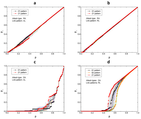
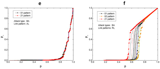
Figure 9.
System robustness of five-layer U.S. aviation network under different interlayer topologies. Twenty-one types of interlink topologies linked with AL or RL under RA, DA, and BA. The critical types are marked. (a) Attack type RA & link pattern AL; (b) Attack type RA & link pattern RL; (c) Attack type DA & link pattern AL; (d) Attack type DA & link pattern RL; (e) Attack type BA & link pattern AL; (f) Attack type BA & link pattern RL.
Figure 9 illustrates the system robustness under RA, DA, and BA based on the five-layer network of 21 different types of interlayer structures constructed by the U.S. aviation network. The following results can be obtained from the figure. Under different attack strategies, different interlink topologies result in differences in the robustness. The five-layer aviation networks reveal the most obvious difference in DA. Under DA, the 01 pattern leads to poor robustness, whereas the 21 pattern leads to improved robustness. Consistent with previous results, the star-like interlink topology represents the extreme type of interlink topologies.
No matter the topology, the aviation network under normal disturbance (RA) can remain with basically unchanged robustness. The aviation network is vulnerable to deliberate attack, as Figure 9a,b shows. As can be seen from Figure 9c–f, the aviation network presents different percolation processes under the deliberate attack. Especially with RL coupling, percolation thresholds of different types of interlayer topologies are very different. Mode 01 (star-like interlinks topology) or mode 02 (tree-like interlinks topology) results in poor robustness, whereas mode 21 (entire interlinks topology) results in improved robustness. In this example, mode 01 represents that the control center of a place only coordinates the relevant flights of the airline; mode 21 represents a coordinated approach that can be considered jointly with the five airlines. That is, in the case of the same early delays, if the coordination method can be considered together with the five airlines, it is better to coordinate only the local affected flights. These results may be attributed to the uniformity of interlink topology. The topological structure between the layers of the most uneven distribution of interlayer structure type (01 and 02 modes) and the layer between the topological structure of the uniformly distributed interlayer structure types (21). Thus, star-like interlinks topology and entire interlinks topology represent the structures of two types of marginal effects between the layers. If the interlayer structure of the multilayer network is considered to be a star-like interlinks topology, the robustness of the multilayer network may be underestimated; on the other hand, the robustness of the multi-layer network may be overestimated if the multi-layer network structure is simply considered to be an entire interlinks topology.
Many scholars assume that if levels A and B have a positive correlation, then levels B and C will also have a positive correlation. The above results are expected to determine the correlation between A and C, although the correlation may not necessarily be direct. However, this study demonstrates that such a simple hypothesis can be extremely flawed. It is found that if the multilayer network is simply regarded as a stacking structure, then the system robustness calculated may be different from that of a nonstacking structure. Moreover, the system robustness calculated by the cascade structure is relatively large. In other words, if there exists an indirect correlation, and we blindly assume that the multilayer network is interdependent, we may ignore some vulnerabilities of the system. Thus, if left unattended, the actual system may suddenly become vulnerable before the theoretical calculation point.
5. Conclusions
In comparison with the two-layer or three-layer coupled interdependent networks, the typical characteristic of coupled multilayer networks above three layers is that they have multiple possible interlink topologies. In this study, multilayer (three-layer or more) coupled networks with different interlink topologies are considered as research objects. The robustness of the multilayer coupling network is investigated through the cascade failure process. The study demonstrates that
- Different interlink topologies exhibit significant influence on the global robustness of the networks to cascading failures.
- Fragile interlink patterns exist in the patterns of interlink topologies.
- With the increased number of layers, the form of the interlink topology becomes increasingly abundant. In general, the 01 pattern (star-like interlink topology) leads to poor robustness. The 10, 12, and 21 patterns, with average interlink-degree distribution, are found to exhibit good global stability. This is probably because the interlink-degree distribution is the most uneven. This study demonstrates that the more uneven the interlink-degree distribution is, the more easily the cascading failures occur when the multilayer network is attacked.
The results of this study will have a profound influence on the robustness and control of multilayer networks. In many practical studies, it is difficult to determine the specific inter-layer dependencies of multilayer coupled networks; however, interlayer dependencies affect the robustness results of multilayer coupled networks. This study is beneficial for other researchers in selecting the appropriate interlink topology for model design when they encounter similar problems. For the study of nonfine multilayer coupled networks, the robustness range of the multilayer coupled networks can be obtained by calculating the star-type interconnection topology and fully connected topology so as to determine whether the robustness of the multilayer coupled networks meets the design requirements. In reality, people are more concerned about the poor robustness; hence, attention needs to be focused on the star-like interlink topology coupled pattern. Thus, for the study of fine modeling, more secure interlayer topological structure relations can be selected to avoid overestimating the robustness of multilayer coupling networks.
As mentioned above, the results of this experiment are not significant for scale-free networks. In addition, the percolation theory used in this study is a static cascade failure measurement method; the results of other methods are not verified at present. However, the results demonstrate the importance of the interlink topology of the multilayer coupled network. The interlink topology affects global robustness, and a fragile interlink pattern exists in the patterns of interlink topologies. The optimal or worst threshold patterns are expected to aid in the model simplification and supervision of multilayer coupling networks.
Author Contributions
Designed Experiments, F.Z. and Y.Y.; Experiments, F.Z. and X.H.; Analysis, F.Z. and M.Z.; Writing-Review & Editing, F.Z.; Supervision, Y.Y. All authors have read and agreed to the published version of the manuscript.
Funding
This research received no external funding.
Acknowledgments
Thanks to dalian university of technology and henan agricultural university. Thanks to the space and information teaching and research office of dalian university of technology for providing server hardware equipment to complete the huge computing work.
Conflicts of Interest
The authors declare no conflict of interest.
References
- Vespignani, A. The fragility of interdependency. Nature 2010, 464, 984–985. [Google Scholar] [CrossRef] [PubMed]
- Buldyrev, S.V.; Parshani, R.; Paul, G.; Stanley, H.E.; Havlin, S. Catastrophic cascade of failures in interdependent networks. Nature 2010, 464, 1025–1028. [Google Scholar] [CrossRef] [PubMed]
- Duenas-Osorio, L.; Craig, J.I.; Goodno, B.J. Seismic response of critical interdependent networks. Earthq. Eng. Struct. D. 2007, 36, 285–306. [Google Scholar] [CrossRef]
- Parshani, R.; Buldyrev, S.V.; Havlin, S. Interdependent networks: Reducing the coupling strength leads to a change from a first to second order percolation transition. Phys. Rev. Lett. 2010, 105, 048701. [Google Scholar] [CrossRef] [PubMed]
- Shao, J.; Buldyrev, S.V.; Braunstein, L.A.; Havlin, S.; Stanley, H.E. Structure of shells in complex networks. Phys. Rev. E 2009, 80, 036105. [Google Scholar] [CrossRef]
- Niu, D.; Yuan, X.; Du, M. Percolation of networks with directed dependency links. Phys. Rev. E 2016, 93, 042312. [Google Scholar] [CrossRef]
- Johansson, J.; Hassel, H. An approach for modelling interdependent infrastructures in the context of vulnerability analysis. Reliab. Eng. Syst. Saf. 2010, 95, 1335–1344. [Google Scholar] [CrossRef]
- Gonzalez, A.D.; Duenas-Osorio, L.; Sanchez-Silva, M.; Medaglia, A.L. The interdependent network design problem for optimal infrastructure system restoration. Comput.-Aided Civ. Inf. 2016, 31, 334–350. [Google Scholar] [CrossRef]
- Boccaletti, S.; Bianconi, G.; Criado, R.; Del Genio, C.I.; Gómez-Gardeñes, J.; Romance, M.; Sendina-Nadal, I.; Wang, Z.; Zanin, M. The structure and dynamics of multilayer networks. Phys. Rep. 2014, 544, 1–122. [Google Scholar] [CrossRef]
- Hong, S.; Lv, C.; Zhao, T.; Wang, B.; Wang, J.; Zhu, J. Cascading failure analysis and restoration strategy in an interdependent network. J. Phys. A 2016, 49, 195101. [Google Scholar] [CrossRef]
- Parshani, R.; Rozenblat, C.; Ietri, D.; Ducruet, C.; Havlin, S. Inter-similarity between coupled networks. EPL 2010, 92, 68002. [Google Scholar] [CrossRef]
- Buldyrev, S.V.; Shere, N.W.; Cwilich, G.A. Interdependent networks with identical degrees of mutually dependent nodes. Phys. Rev. E 2011, 83, 016112. [Google Scholar] [CrossRef] [PubMed]
- Liu, X.; Stanley, H.E.; Gao, J. Breakdown of interdependent directed networks. Proc. Natl. Acad. Sci. USA 2016, 113, 1138–1143. [Google Scholar] [CrossRef] [PubMed]
- Wang, J.; Jiang, C.; Qian, J. Robustness of interdependent networks with different link patterns against cascading failures. Phys. A 2014, 393, 535–541. [Google Scholar] [CrossRef]
- Zhang, W.; Xia, Y.; Ouyang, B.; Jiang, L. Effect of network size on robustness of interconnected networks under targeted attack. Phys. A Stat. Mech. Appl. 2015, 435, 80–88. [Google Scholar] [CrossRef]
- Gao, J.; Liu, X.; Li, D.; Havlin, S. Recent progress on the resilience of complex networks. Energies 2015, 8, 12187–12210. [Google Scholar] [CrossRef]
- Havlin, S.; Kenett, D.Y.; Bashan, A.; Gao, J.; Stanley, H.E. Vulnerability of network of networks. Eur. Phys. J. 2014, 223, 2087–2106. [Google Scholar] [CrossRef]
- Gao, J.; Buldyrev, S.V.; Havlin, S.; Stanley, H.E. Robustness of a network of networks. Phys. Rev. Lett. 2011, 107. [Google Scholar] [CrossRef]
- Gao, J.; Buldyrev, S.V.; Stanley, H.E.; Havlin, S. Networks formed from interdependent networks. Nat. Phys. 2011, 8, 40–48. [Google Scholar] [CrossRef]
- Dong, G.; Gao, J.; Du, R.; Tian, L.; Stanley, H.E.; Havlin, S. Robustness of network of networks under targeted attack. Phys. Rev. E 2013, 87, 052804. [Google Scholar] [CrossRef]
- Dong, G.; Tian, L.; Zhou, D.; Du, R.; Xiao, J.; Stanley, H.E. Robustness of n interdependent networks with partial support-dependence relationship. EPL 2013, 102, 68004. [Google Scholar] [CrossRef]
- Dong, G.; Du, R.; Tian, L.; Liu, R. Robustness of network of networks with interdependent and interconnected links. Phys. A 2015, 424, 11–18. [Google Scholar] [CrossRef]
- Hammersley, J.M. Percolation processes: Lower bounds for the critical probability. Ann. Math. Stat. 1957, 28, 790–795. [Google Scholar] [CrossRef]
- Newman, M.; Strogatz, S.H.; Watts, D.J. Random graphs with arbitrary degree distributions and their applications. Phys. Rev. E 2001, 64, 026118. [Google Scholar] [CrossRef] [PubMed]
- Dorogovtsev, S.N.; Mendes, J.F.F.; Samukhin, A.N. Giant strongly connected component of directed networks. Phys. Rev. E 2001, 64, 025101. [Google Scholar] [CrossRef] [PubMed]
- Gao, Y.; Chen, S.; Nie, S.; Ma, F.; Guan, J. Robustness analysis of interdependent networks under multiple-attacking strategies. Phys. A 2018, 496, 495–504. [Google Scholar] [CrossRef]
- Li, D.; Zhang, Q.; Zio, E. Network reliability analysis based on percolation theory. Reliab. Eng. Syst. Saf. 2015, 142, 556–562. [Google Scholar] [CrossRef]
- Sun, S.; Wu, Y.; Ma, Y.; Wang, L.; Gao, Z.; Xia, C. Impact of degree heterogeneity on attack vulnerability of interdependent networks. Sci. Rep. 2016, 6, 32983. [Google Scholar] [CrossRef]
- Cheng, Z.; Cao, J. Cascade of failures in interdependent networks coupled by different type networks. Phys. A 2015, 430, 193–200. [Google Scholar] [CrossRef]
- Cui, P.; Zhu, P.; Wang, K.; Xun, P.; Xia, Z. Enhancing robustness of interdependent network by adding connectivity and dependence links. Phys. A 2018, 497, 185–197. [Google Scholar] [CrossRef]
- Zhou, F.; Yuan, Y.; Zhang, M. Robustness analysis of interdependent urban critical infrastructure networks against cascade failures. Arab. J. Sci. Eng. 2019, 44, 2837–2851. [Google Scholar] [CrossRef]
- Zhou, F.; Yuan, Y.; Du, Y.; Zhang, M. The Cross-networks Impact Analysis and Assessment in Multilayer Interdependent Networks: A Case Study of Critical Infrastructures. Int. J. Mod. Phys. C 2019, 30, 1940007. [Google Scholar] [CrossRef]
- Freeman, L.C. Centrality in social networks conceptual clarification. Soc. Netw. 1979, 1, 215–239. [Google Scholar] [CrossRef]


© 2020 by the authors. Licensee MDPI, Basel, Switzerland. This article is an open access article distributed under the terms and conditions of the Creative Commons Attribution (CC BY) license (http://creativecommons.org/licenses/by/4.0/).