Article

Investigation and Application of a New Low-Carbon Material (Preplaced Aggregate Concrete) in Concrete-Filled Steel Tube Stub Columns

School of Civil Engineering, Chang’an University, Xi’an 710061, China
*
Author to whom correspondence should be addressed.
Sustainability 2020, 12(5), 1768; https://doi.org/10.3390/su12051768
Submission received: 1 January 2020 / Revised: 18 February 2020 / Accepted: 20 February 2020 / Published: 27 February 2020

Abstract

:
As a new low-carbon material, development of preplaced aggregate concrete (PAC) will achieve huge economic and social benefits. However, few existing research is focused on applying PAC in structural elements. This paper is attempt to apply PAC in concrete-filled steel tube (CFST) stub columns and the bearing behaviors of PAC-filled steel tube (PACFST) stub columns under axial compression are also experimentally investigated. The results indicate that the failure modes of PACFST stub columns are all drum-like failure mode which are analogous to that of CFST stub columns. The axial load-axial strain curves of PACFST stub columns can be roughly divided into elastic stage, elastic-plastic stage and plastic stage. Under the similar ultimate load, the ultimate strains are a bit smaller than that of CFST stub columns. Comparison of the results of ultimate load of PACFST stub columns calculated using the existing relevant standards for the bearing capacity calculation methods of CFST stub columns, GB 50936 and JGJ 138 are much more suitable to assess the bearing capacity of PACFST stub columns. Approximately 15%~20% saving in cement consumption will be accomplished with popularization and utilization of PACFST stub columns as compared with CFST stub columns.

1. Introduction

Concrete-filled steel tube (CFST) structures with virtues of higher bearing capacity [1], greater ductility property [2,3,4], easier construction [5], better seismic performance [6,7] and much more excellent fire-resistant performance [8,9] are widely utilized in high-rise buildings, industrial plants, bridges and underground structures [10,11,12,13,14] recently. With application and popularization of CFST structures, significant economic and social benefits are obtained and a series of technical problems have been solved [2,3,4,5,6,7,15].
Preplaced aggregate concrete (PAC) is a new low-carbon concrete which is different from normal concrete (NC) in three aspects of preparation process, raw materials characteristic and raw materials content [16,17,18,19,20,21,22]. In the aspect of preparation process, PAC is mixing the grout mortar firstly, then placing the coarse aggregate into formworks and finally injecting the grout mortar into the void between coarse aggregate by pumping, while NC is mixing all the raw materials together firstly and then casting them into the formworks. In the aspect of raw materials characteristic, the particle size distribution of coarse aggregate is continuous gradation and the particle size of sand is from 0.15 mm to 2.36 mm in PAC, while the particle size distribution of coarse aggregate is discontinuous gradation and the particle size of sand is from 0.15 mm to 4.75 mm in NC. In the aspect of raw materials content, compared with NC, PAC has higher coarse aggregate content and lower cement content at the similar compressive strength. Based on the above features, PAC has plenty of advantages, such as saving cement, reducing concrete shrinkage, increasing concrete stiffness and so on [22,23,24,25].
With rapid development of infrastructures, the consumption of building materials increases fastly. A series of environmental issues caused by production of building materials are becoming more and more prominent. How to reduce the consumption of building materials has become one of the problems that needs to be solved urgently in construction industry. On the basis of the characteristic of PAC, applying PAC in structures may be one of the effective ways to cut down the consumption of cement in structures. Despite some existing literatures report that the PAC has been already used in underwater construction, massive concrete structures, concrete track construction and nuclear power plant structures [26,27,28], there is still a lack of investigation on application of PAC in widely used structures, such as building and bridge. As a new type of structural forms, CFST structures are widely used in buildings and bridges in recent years. Combined with the characteristic of PAC, using PAC to replace NC in preparation of CFST structural members may be benefit to reduce the consumption of cement in core concrete and will achieve a number of economic and social benefits. It will be a positive attempt to promote energy conservation and emission reduction in the construction industry. However, very few existing research is focused on this field, the most relevant research should be reported by Lv et al. [29], in which the bond behavior of PAC-filled steel tube columns has been studied only. It is still difficult to provide a comprehensive guidance on application of PAC-filled steel tube structures. Thus, it is meaningful to carry out the investigation on the structural properties of PAC-filled steel tube (PACFST) structures.
The CFST column is one of the most widely used structural members in CFST structures. Recently, numerous researches have been conducted on structural properties of CFST columns, typically in compressive behavior [30,31,32], bond behavior [33,34], seismic performance [6,7], fire resistance [8,9,35]. Meanwhile, some design codes have been developed for design of CFST columns by different countries [36,37,38,39,40]. Although a number of design codes have been proposed to depict the properties of CFST columns, considering the difference of PAC and NC, which of the existing design codes is suitable to evaluate the structural properties of PACFST columns is still unclear. Thus, in order to provide insightful guidance on the design of PACFST columns, structural properties of PACFST columns need to be well studied.
Based on the above description, it can be seen that development of the PACFST columns will achieve plenty of benefits, not only on the aspect of structural property, but also on the aspect of sustainability. The sustainable aspects are mainly reflected in saving the consumption of cement in CFST columns, enhancing mechanization during preparation process of CFST columns, reducing the energy consumption during preparation process of CFST columns and so on. Therefore, with requirement of developing sustainable architecture in recent years, PACFST columns will play an important role.
This paper is hence an attempt to propose a new type of CFST stub columns—PACFST stub columns and study the bearing behavior of PACFST stub columns. The bearing behavior of PACFST stub columns are investigated by axial compression tests. The structural parameters including concrete strength, steel strength, concrete type, thickness of steel tube and diameter of steel tube are set as the main variables in this research. On the basis of the experimental results of ultimate bearing capacities of PACFST stub columns under axial compression, compared with the prediction results calculated by existing design codes for CFST stub columns, the bearing capacity calculation methods of PACFST stub columns are also suggested.

2. Materials and Methods

2.1. Test Specimens

10 specimens covering 3 CFST stub columns and 7 PACFST stub columns were prepared in this research. For all specimens, the height-diameter ratio was fixed to 3.0. The changing parameters of all 10 specimens were concrete strength (C40, C50 and C60), steel strength (Q235 and Q345), concrete type (PAC and NC), thickness of steel tube (t = 6mm and 8mm) and diameter of steel tube (D = 219 mm, 299 mm and 351 mm). The details of all specimens were presented in Table 1.

2.2. Material Properties and Concrete Proportions

Concrete used to fill the steel tube included PAC and NC which were all composed with Ordinary Portland Cement, coarse aggregate, sand, water reducing agent and tap water. The grade of Ordinary Portland Cement was 42.5 (GB 175-2007 [41]). The chemical compositions of Ordinary Portland Cement were presented in Table 2. The details of properties of coarse aggregate, sand and water reducing agent were summarized in Table 3. The coarse aggregate I and sand I were utilized to prepared PAC, while the coarse aggregate II and sand II were utilized to prepared NC. The particle size distribution of sand and coarse aggregate were presented in Figure 1. The mix proportions of NC were designed according to the JGJ 55-2011 [42] as shown in Table 4. The mix proportions of PAC were ascertained according to the following principles: coarse aggregate filled molds in a state of loose accumulation and the mortar was used to fill the void between coarse aggregate. After a series of tentative experiments, the mix proportions of PAC were confirmed as illustrated in the Table 4. The compressive strength of NC and PAC were all measured by three cubic specimens of 100 mm × 100 mm × 100 mm following the GB/T 50081-2002 [43]. The yield strength, ultimate strength and elastic modulus of steel tube were tested in accordance to GB/T 228-2010. The test results of properties of steel tube, NC and PAC were presented in Table 1.

2.3. Preparation of Specimens

The steel tube used in this investigation was circular steel tube which was cut following the required sizes. Before filling the concrete into steel tube, a steel plate with thickness of 10 mm was welded to the bottom side of steel tube. The preparation procedure of CFST stub column was: mixing the fresh concrete firstly and then casting them into the steel tube with vibration. The preparation procedure of PACFST stub column was: preparing grout mortar firstly, then casting the coarse aggregate into steel tube layer by layer, finally injecting the grout mortar into the void between coarse aggregate from bottom to top in layer by pumping. The layered height of coarse aggregate was approximately 200 mm. The detail preparation process of the specimens could be found in Lv et al. [29]. All specimens were cured in indoor environment for 28 days.

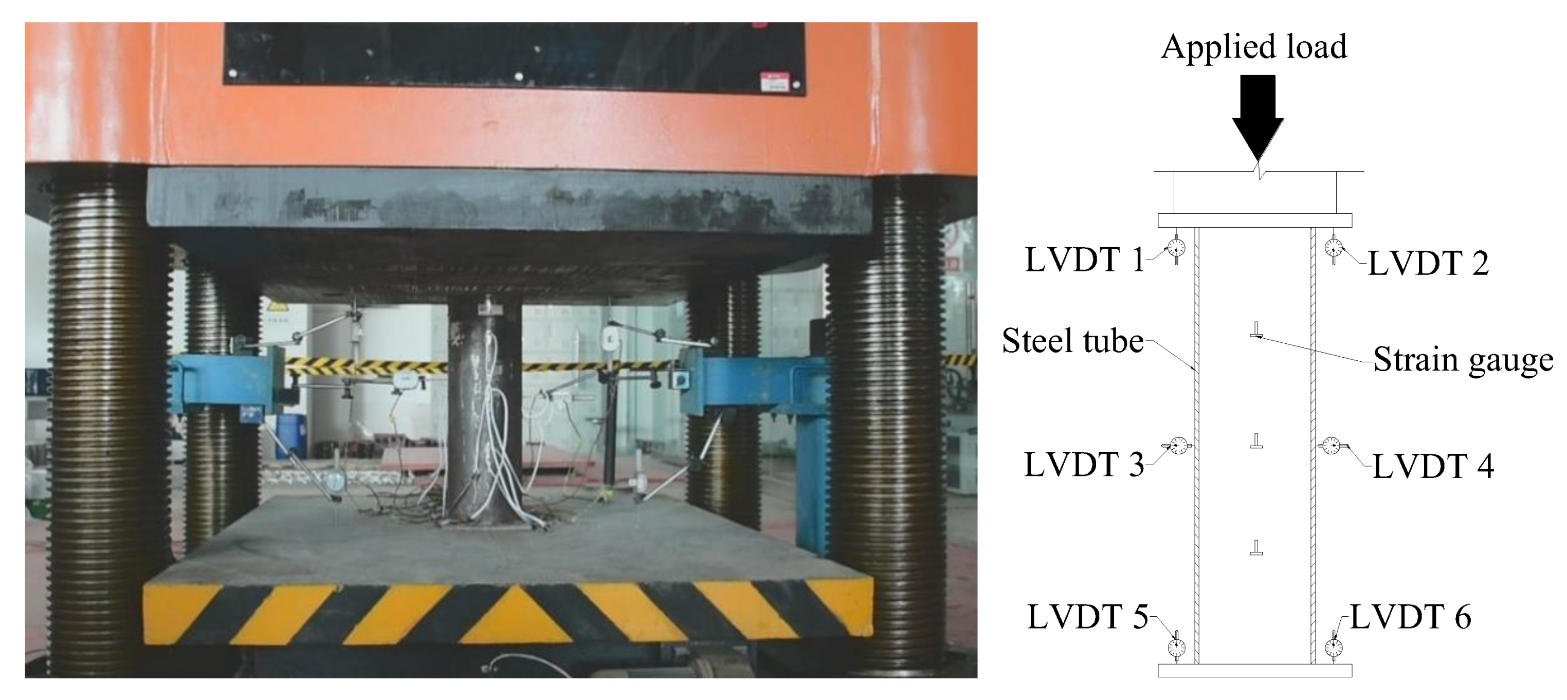
2.4. Experimental Setup

The load was applied by a 30,000 kN computer controlled electro-hydraulic servo universal testing machine in this research as shown in Figure 2. Four linearly varying displacement transducers (LVDTs) were installed at the bottom platen and upper platen of testing machine to detect the axial displacement respectively. The representative axial displacement was acquired from the mean value of the four readings. Two LVDTs were fixed at the middle of the testing specimens to test the hoop displacement. Twelve strain gauges were arranged on the front and back sides of steel tubes to test the lateral and axial strains at 1/4 height, 1/2 height and 3/4 height of steel tube column. All LVDTs and strain gauges were connected to a DH3820 data acquisition system for recording the data. The load was recorded by the testing machine. Loading control mode at a constant rate of 20 kN/min was used to apply load for all specimens. For all specimens, the test was terminated when the axial displacement attained 60 mm.

3. Results and Discussion
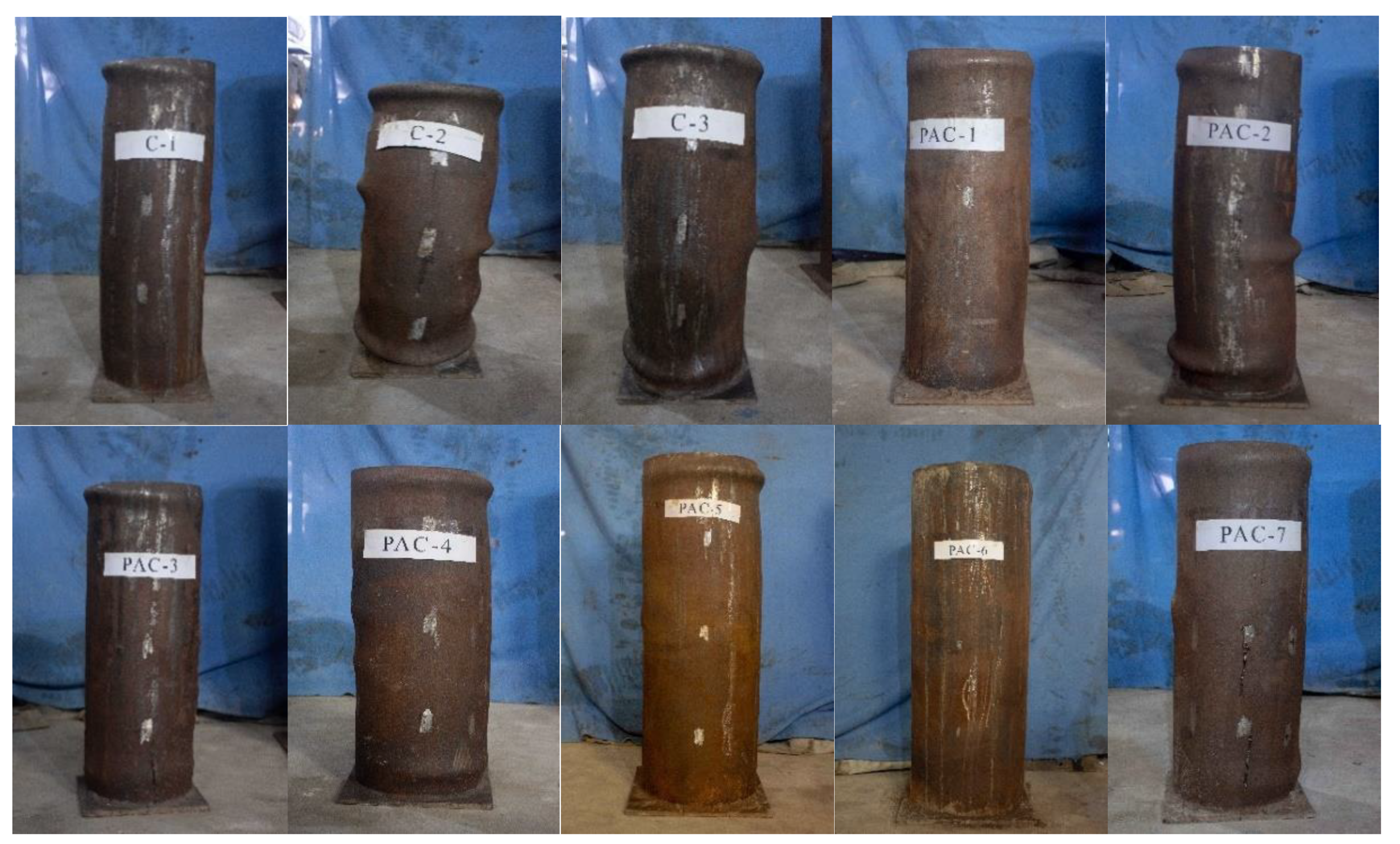
3.1. Failure Modes

The failure modes of CFST stub columns and PACFST stub columns under axial compression were shown in Figure 3. As shown, the failure modes between CFST stub columns and PACFST stub columns were almost similar. At the original stage of loading, there is no obvious change on the surface of specimens with increase of the applied load. As the applied load increased, bulge began to appear near the two ends of specimens accompanied with the local buckling of steel tube occurred. With continuing increase of applied load, bulge began to appear near the middle of steel tube. When the load attained the ultimate load, bearing capacity no longer increased with the displacement raised continually for most of the specimen. Owing to the high confinement index, all specimens exhibited a typical drum-like failure mode. It indicated that there was unobvious effect on axial compression failure characteristic when NC was replaced by PAC to prepare CFST columns.

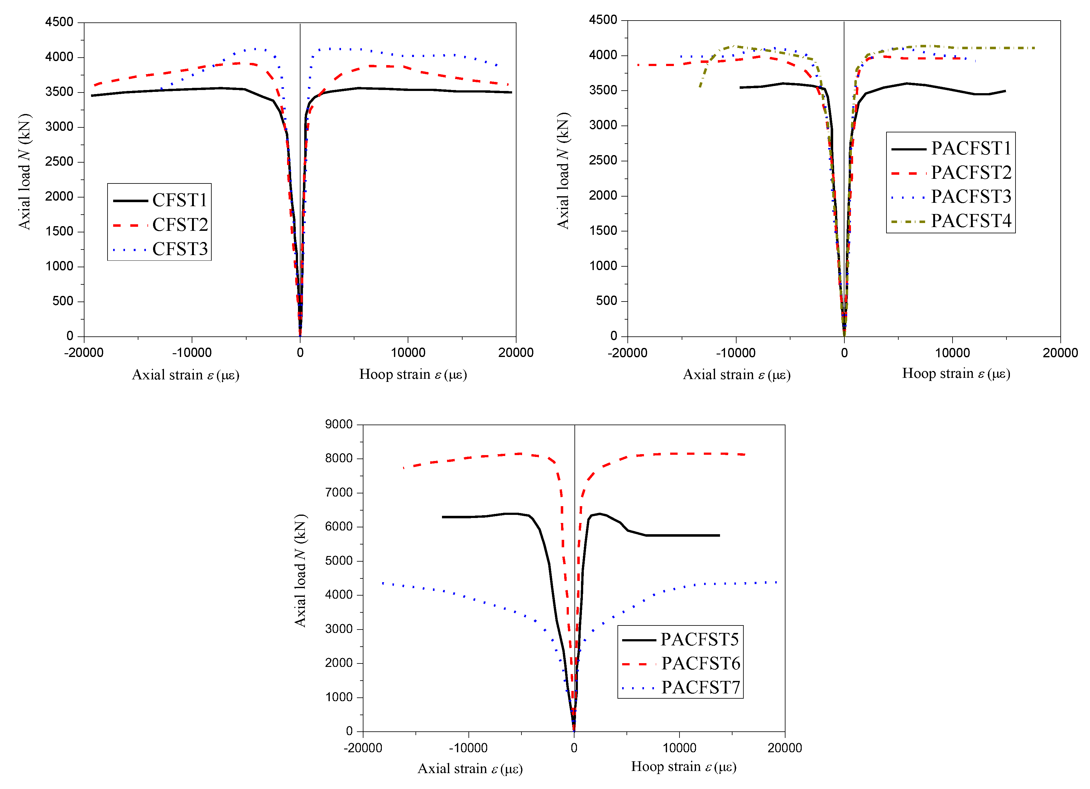
3.2. Axial Load-Axial Strain Curves

Figure 4 presented the axial load-axial strain curves for all ten specimens. The maximum value of applied load or the inflection point of axial load-axial strain curves represented the ultimate bearing capacity of specimens. Despite the axial strains of specimens could be obtained from the readings of mid-height strain gauges or the total axial displacement divided by the specimen length, considering the strain gauges would be broken when the axial displacement was at a relatively large level, the value of the total axial displacement divided by the specimen length was used to evaluate the axial strain in this investigation. From Figure 4, it could be seen that the axial load-axial strain curves for all specimens could be roughly divided into three stages: elastic stage, elastic-plastic stage and plastic stage.
(I)
Elastic stage: This stage covered the load varied from beginning load to about 80% of ultimate load. At this stage, the axial load raised almost linearly with strain. The steel tube and core concrete were all at elastic stage and no visible change would be seen on the surface of specimens.
(II)
Elastic-plastic stage: At this stage, the axial load-axial strain curves changed from initial straight line to curve. The steel tube started to yield and the hoop deformation of core concrete increased rapidly. The bulge appeared at two ends of specimens firstly and then appeared near the middle of steel tube.
(III)
Plastic stage: After ultimate load, the specimens fell in plastic stage. At this stage, the axial load remained roughly unchanged or a slight decrease with strain increased for most of the specimens. Only the axial load of PACFST4 stub columns increased with strain which might be mainly due to the larger confinement index. All PACFST stub columns exhibited favorable ductility after ultimate load which were in keeping with that of CFST stub columns.

3.3. Parametric Analysis

3.3.1. Effect of Concrete Type and Concrete Strength

Figure 5 presented the variation of ultimate load and strain at ultimate load with concrete type and concrete strength. It could be seen the ultimate load of PACFST stub columns and CFST stub columns were almost the same when the compressive strength of PAC and NC were similar. The ultimate bearing capacity of PACFST stub columns enhanced with increase of concrete strength which were consistent with the variation of CFST stub columns. The strains of PACFST stub columns at ultimate load were a bit less than that of CFST stub columns. It might be mainly due to the higher elastic modulus of PAC compared with that of NC. Compared with CFST stub columns, at the similar ultimate load, the decrease in strains at ultimate load were 8.15% for C40, 7.14% for C50 and 15.48% for C60. Thus, at the same bearing capacity, replacing NC by PAC to prepare CFST column was benefit to reduce the deformation of CFST column under axial load.

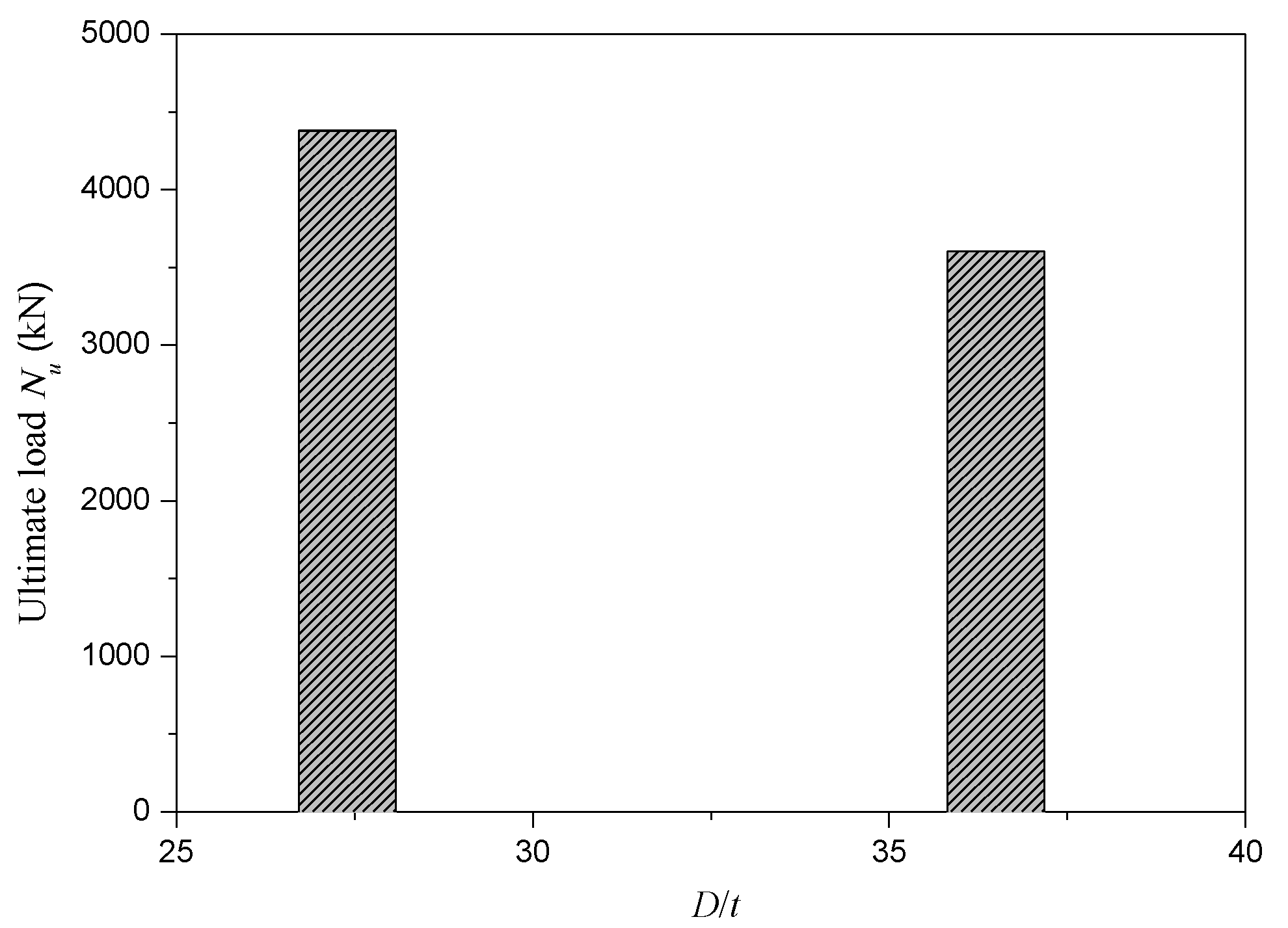
3.3.2. Effect of D/t Ratio

The variation of ultimate load of PACFST stub columns with D/t ratio were shown in Figure 6. In here, the sectional dimension and strength grade of core PAC remained unchanged. It could be seen that as D/t ratio increased from 27.4 to 36.5, the ultimate load of PACFST stub column decreased from 4379 kN to 3605 kN, which was equivalent to about a 17.7% reduction. The variation of ultimate load of PACFST stub columns with D/t ratio were in keeping with that of CFST stub columns.

3.3.3. Effect of Confinement Factor

Under the same PAC strength grade, steel strength and external diameter of steel tube, the ultimate load Nu of PACFST stub columns varied with confinement index ξ were illustrated in Figure 7. It could be discovered that the ultimate load Nu of PACFST stub columns increased with increase of confinement index ξ which were in accordance with the CFST stub columns. Increasing of confinement index ξ from 1.26 to 1.47 and 1.79 resulted in a rise of the ultimate load Nu of PACFST stub columns from 3605 kN to 4136 kN and 4379 kN respectively. Apparently, about 14.8% and 21.5% increment of ultimate load Nu of PACFST stub columns would be occurred as confinement index ξ increased from 1.26 to 1.47 and from 1.26 to 1.79. This might be mainly attributed to the fact that the higher the confinement index ξ, the greater the confinement effect of PACFST stub columns would be. Increasing the confinement effect of PACFST stub columns was benefit to enhance the bearing capacity of PACFST stub columns which was in consonance with CFST stub columns.

3.4. Strain Response

Figure 8 depicted the axial load-hoop strain curves and axial load-axial strain curves at mid-height of steel tube for all specimens. It could be discovered that the axial strain and hoop strain increased with increase of the applied load. For all specimens, the shape of axial load-hoop and strain axial load-axial strain curves were quite similar. Both of the axial load-hoop and strain axial load-axial strain curves could be roughly divided into three stages which were analogous to the axial load-strain curves observed in Section 3.2. At the elastic stage, the axial strain and hoop strain was all in a lower level, meanwhile, the ratios of axial strain to hoop strain were approximately equal to 3. It indicated that the mid-height section of steel tube were mainly under compression during this stage for all specimens. Once the specimens entered into elastic-plastic stage, both of the axial strain and hoop strain enlarged rapidly while the axial load enhanced slightly. A significant confinement effect could be provided by external steel tube to the core concrete which enhanced the deformation capacity and compressive resistance of core concrete remarkably. After the ultimate load, the specimens fell into the plastic stage, an obvious rise in axial strain and hoop strain would be occurred while the axial load remained almost unchanged or a slight decrease. The specimens exerted favorable ductility. Compared with the axial load-axial strain curves as discussed in Section 3.2, owning to the measuring range of strain gauges, the maximum values of axial strain and hoop strain were much smaller. Thus, in this investigation, the correlation between axial load and axial strain was established using the axial load-axial strain curves as shown in Section 3.2.

3.5. Bearing Capacity Calculation

In order to evaluate the bearing capacity of CFST stub columns under axial compression, plenty of bearing capacity calculation methods were suggested in relevant standards, the representative standards were ACI code [36], Japanese code AIJ [37], Eurocode 4 [38], Chinese code GB50936-2014 [39] and Chinese code JGJ 138-2016 [40]. As a new type of CFST columns, the bearing capacity calculation method of PACFST stub columns under axial compression was still unclear. It was not conducive to popularize and use the PACFST stub columns. For detecting which of the above methods was suitable for evaluating the bearing capacity calculation of PACFST stub columns under axial compression, the calculated values of ultimate load of PACFST stub columns under axial compression using the above methods were compared with the experimental value. Then the most appropriate bearing capacity calculation method of PACFST stub columns was suggested.
(1) ACI code
According to the ACI code, the ultimate compressive resistance of CFST stub columns under axial compression could been calculated as following:
P u = f y A s + 0.85 f c A c
where Pu is the predicted ultimate compressive resistance, fc is the concrete compressive strength.
(2) Japanese code AIJ
According to the Japanese code AIJ, the ultimate compressive resistance of CFST stub columns under axial compression could be determined as following:
P u = 0.85 f c A c + ( 1 + η ) f y A s    L / D 4
where η is the coefficient related to the shape of steel tube section, η = 0.24 and η = 0 for circular tube and square tube respectively.
(3) Eurocode 4
In terms of the Eurocode 4, the ultimate compressive resistance of CFST stub columns under axial compression could be determined by the following formulas:
P u = { η a f y A s + f c A c ( 1 + η c t f y D f c ) f y A s + f c A c
η a = 0.25 ( 3 + 2 λ )
η c = 4.9 18.5 λ + 17 λ 2
λ = P p l , R k P c r
P p l , R k = A s f y + 0.85 A c f c
P c r = π 2 K L E I e f f
E I e f f = E s I s + K e E c I c
where Es and Ec are elastic modulus of steel tube and core concrete, Is and Ic are second moment of area of steel tube and core concrete, Ke is a correction factor which is equal to 0.6.
(4) Chinese code GB50936-2014
Based on the Chinese code GB50936-2014, the ultimate compressive resistance of CFST stub columns under axial compression could be described as following:
P u = ( A s + A c ) ( 1.212 + m ξ + n ξ 2 ) f c
m = { 0.176 f y / 213 + 0.974     for   cirular   cross   sec tion 0.131 f y / 213 + 0.723     for   square   cross   sec tion
n = { 0.104 f c / 14.4 + 0.031     for   cirular   cross   sec tion 0.070 f c / 14.4 + 0.026     for   square   cross   sec tion
(5) Chinese code JGJ 138-2016
For the CFST stub columns with L/D ratio under 4.0, the ultimate compressive resistance of CFST stub columns under axial compression could be specified as follows:
P u = { 0.9 φ l f c A c ( 1 + α ξ ) 0.9 φ l f c A c ( 1 + ξ + ξ )
where φl is the coefficient related to the L/D ratio, equal to 1.0 herein.
Using the above bearing capacity calculation methods of CFST stub columns, the ultimate bearing capacities of PACFST stub columns under axial compression were calculated and the results were shown in Table 5. Meanwhile, the statistical analysis results between experimental results and calculation results were also given in Table 5. The results calculated by Eurocode 4 was larger than the experimental results for all the specimens. It showed that using the Eurocode 4 to describe the ultimate bearing capacities of PACFST stub columns under axial compression was insecure. On the contrary, the results calculated by ACI, AIJ, GB 50936 and JGJ 138 were all smaller than the experimental results for all the specimens. By comparison, it could be observed that the results calculated by GB 50936 and JGJ 138 were much more close to the experimental results. It was therefore advised that using the GB 50936 and JGJ 138 to evaluate the ultimate bearing capacities of PACFST stub columns under axial compression.

4. Conclusion

In this paper, 3 CFST stub columns and 7 PACFST stub columns were prepared and the axial compression tests were performed. Based on the axial compression tests, the influences of structural parameters including concrete strength, steel strength, concrete type, diameter of steel tube and thickness of steel tube on the ultimate bearing capacities of PACFST stub columns under axial compression were analyzed. The bearing capacity calculation methods of PACFST stub columns under axial compression were also suggested. The following conclusions could be drawn:
(1)
The PACFST stub columns under axial compression exhibited a typical drum-like failure mode which were analogous to that of CFST stub columns. Meanwhile, the axial load-axial strain curves of PACFST stub columns could be roughly divided into three stages which were also analogous to that of CFST stub columns.
(2)
Under the same strength grade of core concrete, steel strength and external diameter of steel tube, the ultimate load of PACFST stub columns and CFST stub columns were almost the same, the strains at ultimate load of PACFST stub columns were a bit smaller than that of CFST stub columns.
(3)
Compared the bearing capacity calculation results of PACFST stub columns calculated by existing relevant standards, the results calculated by GB 50936 and JGJ 138 coincided well with the experimental results. Thus, bearing capacity calculation method of CFST stub columns mentioned in GB 50936 and JGJ 138 could be utilized to evaluate the bearing capacity of PACFST stub columns under axial compression.
(4)
Under the similar bearing capacity of PACFST stub columns and CFST stub columns, about 15%~20% saving in cement consumption would be achieved when NC was replaced by PAC to prepared CFST stub columns. Development of PAC in CFST stub columns was benefit to reduce the consumption of cement in CFST structures and would achieve a number of economic and social benefits.
This research attempts an application of PAC in CFST stub columns and provides a guidance on the design of stub circular PACFST stub columns under axial compression. Nevertheless, the properties of slender circular PACFST stub columns under axial compression and PACFST stub columns under eccentric compression are still unclear. These properties of PACFST columns will be carried out in our further research.

Author Contributions

Investigation, J.L. and T.Z.; Conceptualization, J.L. and T.Z; Funding acquisition, J.L.; Methodology and Formal Analysis, K.L.; Data Curation, K.L.; Writing-Original Draft Preparation, J.L.; Writing-Review & Editing, J.L. All authors have read and agreed to the published version of the manuscript.

Funding

This research was funded by National Natural Science Foundation of China (Grant No. 51908046), Key Research and Development Program of Shaanxi Province (Grant No. 2019GY-206), China Postdoctoral Science Foundation (Grant No. 2019M653517) and Fundamental Research Funds for the Central Universities (Grant No. 310823172001).

Conflicts of Interest

The authors declare no conflict of interest.

References

  1. Han, L.H.; Li, W.; Bjorhovde, R. Developments and advanced applications of concrete-filled steel tubular (CFST) structures: Members. J. Constr. Steel Res. 2014, 100, 211–228. [Google Scholar] [CrossRef]
  2. Wang, R.; Han, L.H.; Hou, C.C. Behavior of concrete filled steel tubular (CFST) members under lateral impact: Experiment and FEA model. J. Constr. Steel Res. 2013, 80, 188–201. [Google Scholar] [CrossRef]
  3. Roeder, C.W.; Lehman, D.E.; Bishop, E. Strength and Stiffness of Circular Concrete-Filled Tubes. J. Struct. Eng. 2010, 136, 1545–1553. [Google Scholar] [CrossRef]
  4. Yu, Z.W.; Ding, F.X.; Cai, C.S. Experimental behavior of circular concrete-filled steel tube stub columns. J. Constr. Steel Res. 2007, 63, 165–174. [Google Scholar] [CrossRef]
  5. Wang, Z.B.; Tao, Z.; Han, L.H.; Uy, B.; Lam, D.; Kang, W.H. Strength, stiffness and ductility of concrete-filled steel columns under axial compression. Eng. Struct. 2017, 135, 209–221. [Google Scholar] [CrossRef]
  6. Fang, S.; Liu, F.; Xiong, Z.; Fang, J.S.; Li, L.J. Seismic performance of recycled aggregate concrete-filled glass fibre-reinforced polymer-steel composite tube columns. Constr. Build. Mater. 2019, 225, 997–1010. [Google Scholar] [CrossRef]
  7. Xu, J.J.; Chen, Z.P.; Zhao, X.Y.; Demartino, C.; Ozbakkaloglu, T.; Xue, J.Y. Seismic performance of circular recycled aggregate concrete-filled steel tubular columns: FEM modelling and sensitivity analysis. Thin-Walled Struct. 2019, 141, 509–525. [Google Scholar] [CrossRef]
  8. Yu, M.; Wang, T.; Huang, W.J.; Yuan, H.X.; Ye, J.Q. Fire resistance of concrete-filled steel tube columns with preload. Part I: Experimental investigation. Compos. Struct. 2019, 223, 110994. [Google Scholar] [CrossRef]
  9. Wang, K.; Ben, Y. Fire resistance of concrete-filled high strength steel tubular columns. Thin-Walled Struct. 2013, 71, 46–56. [Google Scholar] [CrossRef] [Green Version]
  10. Xu, W.; Han, L.H.; Li, W. Seismic performance of concrete-encased column base for hexagonal concrete-filled steel tube: Experimental study. J. Constr. Steel Res. 2016, 121, 352–369. [Google Scholar] [CrossRef]
  11. Li, Y.; Cai, C.C.; Liu, Y.; Chen, Y.J.; Liu, J.F. Dynamic analysis of a large span specially shaped hybrid girder bridge with concrete-filled steel tube arches. Eng. Struct. 2016, 106, 243–260. [Google Scholar] [CrossRef] [Green Version]
  12. Xin, L.F.; Li, X.Z.; Zhang, Z.T.; Zhao, L.F. Seismic behavior of long-span concrete-filled steel tubular arch bridge subjected to near-fault fling-step motions. Eng. Struct. 2019, 180, 148–159. [Google Scholar] [CrossRef]
  13. He, A.; Zhao, Q. Experimental and numerical investigations of concrete-filled stainless steel tube stub columns under axial partial compression. J. Constr. Steel Res. 2019, 158, 405–416. [Google Scholar] [CrossRef]
  14. Qiao, Q.Y.; Zhang, W.W.; Mou, B.; Cao, W.L. Seismic behavior of exposed concrete filled steel tube column bases with embedded reinforcing bars: Experimental investigation. Thin-Walled Struct. 2019, 136, 367–381. [Google Scholar] [CrossRef]
  15. Cao, V.V. Experimental Behaviour of Recycled Aggregate Concrete-Filled Steel Tubes Under Axial Loading. Int. J. Civ. Eng. 2019, 17, 1341–1351. [Google Scholar]
  16. ACI. Committee 304. Guide for Measuring, Mixing, Transporting, and Placing Concrete; American Concrete Institute: Farmington Hill, MI, USA, 2005. [Google Scholar]
  17. Nehdi, M.L.; Najjar, M.F.; Soliman, A.M.; Azabi, T.M. Novel eco-efficient Two-Stage Concrete incorporating high volume recycled content for sustainable pavement construction. Constr. Build. Mater. 2017, 146, 9–14. [Google Scholar] [CrossRef]
  18. Felekoğlu, B. Optimization of self-compacting filling grout mixtures for repair purposes. Constr. Build. Mater. 2008, 22, 660–667. [Google Scholar] [CrossRef]
  19. Mirza, J.; Mirza, M.S.; Roy, V.; Saleh, K. Basic rheological and mechanical properties of high-volume fly ash grouts. Constr. Build. Mater. 2002, 16, 353–363. [Google Scholar] [CrossRef]
  20. Abdelgader, H.S.; Górsk, J. Stress-Strain Relations and Modulus of Elasticity of Two-Stage Concrete. J. Mater. Civ. Eng. 2003, 15, 329–334. [Google Scholar] [CrossRef]
  21. Najjar, M.F.; Nehdi, M.L.; Soliman, A.M.; Azabi, T.M. Damage mechanisms of two-stage concrete exposed to chemical and physical sulfate attack. Constr. Build. Mater. 2017, 137, 141–152. [Google Scholar] [CrossRef]
  22. Najjar, M.F.; Soliman, A.M.; Nehdi, M.L. Critical overview of two-stage concrete: Properties and applications. Constr. Build. Mater. 2014, 62, 47–58. [Google Scholar] [CrossRef]
  23. Yoon, J.Y.; Kim, J.H. Mechanical properties of preplaced lightweight aggregates concrete. Constr. Build. Mater. 2019, 216, 440–449. [Google Scholar] [CrossRef]
  24. Li, P.P.; Yu, Q.L.; Brouwers, H.J.H.; Chen, W. Conceptual design and performance evaluation of two-stage ultra-low binder ultra-high performance concrete. Cem. Concr. Res. 2019, 125, 105858. [Google Scholar] [CrossRef]
  25. Chen, Y.H.; Liu, S.; Zhu, B.L.; Liu, R.; Wang, Y. Preparation of preplaced aggregate concrete and experimental study on its strength. Constr. Build. Mater. 2020, 229, 116847. [Google Scholar] [CrossRef]
  26. Lee, S.; Jang, S.Y.; Kim, C.Y.; Ahn, E.J.; Kim, S.P.; Gwon, S.; Shin, M. Effects of Redispersible Polymer Powder on Mechanical and Durability Properties of Preplaced Aggregate Concrete with Recycled Railway Ballast. Int. J. Concr. Struct. Mater. 2018, 12, 69. [Google Scholar] [CrossRef]
  27. Bras, A.; Gião, R.; Lúcio, V.; Chastre, C. Development of an injectable grout for concrete repair and strengthening. Cem. Concr. Compos. 2013, 37, 185–195. [Google Scholar] [CrossRef] [Green Version]
  28. Abdelgader, H.S.; Najjar, M.F.; Azabi, T.M. Study of underwater concrete using two-stage (pre-placed aggregate) concrete in Libya. Struct. Concr. 2010, 11, 161–165. [Google Scholar] [CrossRef]
  29. Lv, J.; Zhou, T.H.; Du, Q.; Li, K.L.; Jin, L.W. Research on the Bond Behavior of Preplaced Aggregate Concrete-Filled Steel Tube Columns. Materials 2020, 13, 300. [Google Scholar] [CrossRef] [Green Version]
  30. Tian, H.W.; Zhou, Z.; Wei, Y.; Wang, Y.Q.; Lu, J.P. Experimental investigation on axial compressive behavior of ultra-high performance concrete (UHPC) filled glass FRP tubes. Constr. Build. Mater. 2017, 154, 644–657. [Google Scholar] [CrossRef]
  31. Yang, J.L.; Wang, J.Z.; Wang, X.P.; Cheng, L.; Wang, Z.R. Compressive Behavior of Circular Tubed Steel-Reinforced High-Strength Concrete Short Columns. J. Struct. Eng. 2019, 145, 04019086. [Google Scholar] [CrossRef]
  32. Abed, F.; AlHamaydeh, M.; Abdalla, S. Experimental and numerical investigations of the compressive behavior of concrete filled steel tubes (CFSTs). J. Constr. Steel Res. 2013, 80, 429–439. [Google Scholar] [CrossRef]
  33. Tao, Z.; Song, T.Y.; Uy, B.; Han, L.H. Bond behavior in concrete-filled steel tubes. J. Constr. Steel Res. 2016, 120, 81–93. [Google Scholar] [CrossRef]
  34. Chen, Y.; Feng, R.; Shao, Y.B.; Zhang, X.T. Bond-slip behaviour of concrete-filled stainless steel circular hollow section tubes. J. Constr. Steel Res. 2017, 130, 248–263. [Google Scholar] [CrossRef]
  35. Wang, J.H.; He, J.; Xiao, Y. Fire behavior and performance of concrete-filled steel tubular columns: Review and discussion. r of concrete-filled stainless steel circular hollow section tubes. J. Constr. Steel Res. 2019, 157, 19–31. [Google Scholar] [CrossRef]
  36. ACI. Committee 318. Building Code Requirements for Structural Concrete and Commentary; American Concrete Institute: Farmington Hills, MI, USA, 2011. [Google Scholar]
  37. AIJ. Recommendations for Design and Construction of Concrete Filled Steel Tubular Structures; Architectural Institute of Japan (AIJ): Tokyo, Japan, 2008. [Google Scholar]
  38. European Committee for Standardization. Eurocode 4: Design of Composite Steel and Concrete Structures; European Committee for Standardization: Brussels, Belgium, 2004. [Google Scholar]
  39. GB50936-2014. Technical Code for Concrete Filled Steel Tubular Columns; China Architecture and Building Press: Beijing, China, 2014.
  40. JGJ 138-2016: Code for Design of Composite Structures; China Architecture and Building Press: Beijing, China, 2016.
  41. GB 175-2007: Common Portland Cement; China Standards Press: Beijing, China, 2007.
  42. JGJ 55-2011: Specification for Mix Proportion Design of Ordinary Concrete; China Architecture and Building Press: Beijing, China, 2011.
  43. GB/T 50081-2002: Standard for Test Method of Mechanical Properties on Ordinary Concrete; China Architecture and Building Press: Beijing, China, 2003.
Figure 1. Particle size distribution of sand and coarse aggregate.
Sustainability 12 01768 g001
Figure 2. Experiment apparatus.
Sustainability 12 01768 g002
Figure 3. Failure modes.
Sustainability 12 01768 g003
Figure 4. Axial load-strain curves for all specimens.
Sustainability 12 01768 g004
Figure 5. Variation of ultimate load and strain corresponding to ultimate load with concrete strength and concrete type.
Sustainability 12 01768 g005
Figure 6. Variation of ultimate load Nu of PACFST stub columns with D/t ratio.
Sustainability 12 01768 g006
Figure 7. Variation of ultimate load Nu of PACFST stub columns with confinement index ξ.
Sustainability 12 01768 g007
Figure 8. Axial load-axial strain and axial load-hoop strain curves for all specimens.
Sustainability 12 01768 g008
Table 1. Details of specimens.
Specimen IDD × t × L (mm3)fcu (MPa)fy (MPa)fu (MPa)Es (MPa)ξAs/Ac
PACFST1219 × 6 × 65744.73405102.05 × 1051.2611.9%
PACFST2219 × 6 × 65757.23405102.05 × 1050.9811.9%
PACFST3219 × 6 × 65765.73405102.05 × 1050.8211.9%
PACFST4219 × 6 × 65744.73984922.11 × 1051.4711.9%
PACFST5299 × 8 × 89744.73415032.06 × 1051.2311.6%
PACFST6351 × 8 × 105344.73435112.06 × 1051.049.8%
PACFST7219 × 8 × 65744.73324922.08 × 1051.7311.9%
CFST1219 × 6 × 65746.43405102.05 × 1051.2111.9%
CFST2219 × 6 × 65756.83405102.05 × 1050.9911.9%
CFST3219 × 6 × 65767.13405102.05 × 1050.8111.9%
Note: D is the external diameter of the circular steel tube; t is the thickness of the steel tube; L is the height of the steel tube; fcu is the cubic compressive strength of concrete; fy is the yield strength of steel tube; fu is the ultimate strength of steel tube; Es is the elastic modulus of steel tube; ξ is the confinement index that equals to fyAs/fcAc; Ac is the cross-section area of core concrete; As is the cross-section area of steel tube.
Table 2. Chemical compositions of cement.
Mineral CompositionsContent/%
CaOSiO2Al2O3Fe2O3MgOSO3K2ONa2OLoss on Ignition
Ordinary Portland Cement60.3222.344.554.182.052.870.510.412.77
Table 3. Details of raw materials properties.
MaterialsTypeProperties
coarse aggregate ICrushed coarse aggregateCrushing index: 9.5%
Loose bulk density: 1360 kg/m3
Apparent density: 2520 kg/m3
coarse aggregate IICrushed coarse aggregateCrushing index: 8.6%
Loose bulk density: 1420 kg/m3
Apparent density: 2520 kg/m3
Sand IRiver sandModulus of fineness: 3.58
Bulk density: 1450 kg/m3
Apparent density: 2610 kg/m3
Sand IIRiver sandModulus of fineness: 2.68
Bulk density: 1430 kg/m3
Apparent density: 2625 kg/m3
Water reducing agentPolycarboxylate superplasticizerSolid content: 40%
Water reduction rate: 25%
Table 4. Mix proportions of PAC and NC.
Concrete GradeWeight Per Cubic Meter (kg/m3)W/B
CementSand ISand IICoarse Aggregate ICoarse Aggregate IIWater ReducerWater
C60 (PAC)385578 1360 5.781160.30
C50 (PAC)330660 1360 4.981000.30
C40 (PAC)310620 1360 2.481240.40
C60 (NC)500 660 10807.501600.32
C50 (NC)470 580 11807.051700.36
C40 (NC)420 570 12704.201850.44
Table 5. Comparison between experimental results and calculation results for all specimens.
NumberNu (kN)ACIAIJEurocode 4GB 50936JGJ 138
Pu (kN)Pu/NuPu (kN)Pu/NuPu (kN)Pu/NuPu (kN)Pu/NuPu (kN)Pu/Nu
CFST1356223220.69126910.80140271.19930550.91033580.943
CFST2387925370.68629050.78642791.15733870.91636970.953
CFST3412728040.75131730.85045941.23038051.01937350.905
PACFST1360322870.69326560.80539851.20730010.90933000.916
PACFST2398925450.68729140.78642891.15734000.91737060.929
PACFST3410627740.74931430.84945581.23137581.01537030.902
PACFST4413625200.70029510.82044801.24532700.90835990.870
PACFST5638942170.69248900.80273321.20355480.91060940.954
PACFST6815453720.68661700.78891731.17271810.91778280.960
PACFST7437926470.69731220.82247261.24533320.87837960.867
Average0.7030.8111.2050.9300.920
Cov0.0360.0290.0280.0500.037

