Abstract
The neutron shielding glass is widely used in nuclear/fusion plants. To improve its temperature resistance and heat insulation, a Gadolinium (Gd)-containing laminate vacuum multiple glass is proposed by using the vacuum insulation method. A 3D finite element model validated by theoretical calculation was developed to analyse the heat transfer path and numerical simulation of the multiple glass was carried out to obtain the temperature distribution and the maximum temperatures of the organic glass in relation to dynamic working temperatures, the sealing agent width, view size, and vacuum thermal conductivity. The results show that the vacuum layer between common glasses can make the work temperature of neutron shielding glass increase. The multiple glass has good heat-shielding performance and it is expected to work in a high-temperature environment. In addition, the vacuum layer between the common glasses and the sealing agent width decay with respect to the view size and vacuum thermal conductivity show an increase in the working temperature of the neutron shielding glass. It was concluded that the order of affecting the temperatures of the organic glass follows the pattern of: view size > vacuum thermal conductivity > sealing agent width.
1. Introduction
As a kind of neutral particle, the neutron has a strong penetrating power. It appears widely in nuclear/fusion plants [1,2,3,4]. A transparent window (viewing window) is required for visual inspection in nuclear/fusion plants. The neutron shielding glass has good optical properties, easy and cheap production advantages, and it attracts many researchers to study. Gamma and neutron shielding characterisations of the Ag2O–V2O5–MoO3–TeO2 quaternary tellurite glass system were assessed by using the Geant4 simulation toolkit and Phy-X software [5]. Neutron shielding capability of CoO and NiO added bioactive glasses were investigated using MCNPX simulation code [6]. Many efforts have been focused on improving neutron shielding properties for silicate-, borate-, and tellurite-based glasses [7,8,9]. In mechanical performance, elastic properties of neutron shielding glasses were studied [10,11,12,13]. Gd-containing neutron shielding glass has good shielding properties for neutrons, X-rays, and gamma rays. However, its glass transition temperature is lower. When Gd-containing organic glass was prepared with Gd (MA)3 of 30%, the maximum glass transition temperature was reported to be 138.4 °C [14]. Neutron shielding organic glass can reduce the damage to the human body next to view glass or machines. It is convenient for workers or robots to observe. However, it has the problem of low-temperature resistance and poor heat insulation, and cannot work in the neutron and high-temperature environment of nuclear/fusion plants, such as nuclear accidents associated with fire [15]. Therefore, it is necessary to develop a new neutron shielding glass with high temperature resistance and high heat insulation.
The vacuum has better thermal insulation performance than any material [16,17]. Common glass has high temperature resistance and a maximum glass transition temperature which is more than 1000 °C. So, vacuum glass formed by a vacuum and two common glasses has better thermal insulation performance and high temperature resistance [18,19]. If vacuum glass and neutron shielding glass were combined to a new multiple glass, this glass will have the advantage of neutron shielding, optical properties, thermal insulation performance, and high temperature resistance. Then, it could work in a high-temperature and neutron radiating environment. In this study, Gd-containing laminate vacuum multiple glass is proposed. Its structure and working principle are introduced. A three-dimensional finite element model validated by theoretical calculation is developed to simulate the heat transfer path and validated with the thermal mathematical model. Numerical simulation of the multiple glass is carried out to obtain the temperature distribution and the maximum temperature of the organic glass is discussed by changing the work temperature, the sealing agent width, view size, and vacuum thermal conductivity. This study has an important theoretical and practical value for developing a neutron shielding glass with high temperature resistance and high heat insulation as a candidate window material for nuclear/fusion plants.
2. Materials and Methods
2.1. The Structure of the Gd-Containing Laminate Vacuum Multiple Glass
A Gd-containing laminate vacuum multiple glass is proposed, as shown in Figure 1. It includes Gd-containing organic glass, Gd-containing lined adhesive, common glass, a vacuum layer, the support, and the sealing agent. The Gd-containing lined adhesive is set between the Gd-containing organic glass and the middle common glass. The vacuum layer is formed by sealing two common glasses with the sealing agent. To reduce the high-pressure difference between the vacuum layer and the outside atmosphere, the supports are set at a certain distance. This new glass can solve the following problems:
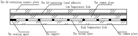
Figure 1.
The structure of the Gd-containing laminate vacuum multiple glass.
- The problem of neutron shielding: the Gd-containing organic glass contains the Gd element, which can shield the neutron glass;
- The problem of heat insulation: the vacuum layer is used to increase the heat resistance, and reduce the heat exchange between the low- and high-temperature sides;
- The problem of high temperature resistance: compared with the neutron organic glass, the common glass has high temperature resistance (the top temperature is about 1580 °C), which is set at the high temperature side.
2.2. Mathematical Modelling Approach
When the vacuum multiple glass is working, its heat transfer includes three ways: convection, conduction, and radiation, as shown in Figure 2.
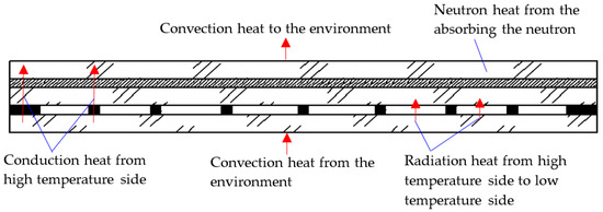
Figure 2.
The heat transfer paths of the Gd-containing laminate vacuum multiple glass.
2.2.1. Convective Heat Transfer Process
Two sides of the vacuum multiple glass have the convection heat, as shown in Figure 2, and the Newton cooling law is used as follows:
where (W/m2) refers to the heat flux from the convective heat load. (W/(m2·K)) refers to the convection coefficient, which depends on the air flow rate past the heat transfer surface, the air’s thermal conductivity, air viscosity, air specific heat, temperature difference between the bulk air and the heat transfer surface, and so on. (K) refers to the temperatures of the inside/outside. (K) is the environment temperature. In ANSYS14.5, because the structure is heterogeneous, the convection coefficient was not considered in detail. However, it was assumed that is equal to , and the convection heat was assumed to be the environment temperature.
2.2.2. Conductive Heat Transfer Process
The vacuum multiple glass is also the heat source, because it can absorb the neutron and the neutron heat is produced, as shown in Figure 2. Because the neutron is absorbed through the glass, the exponential function is used as the distribution of the thermal energy [20,21], and it can be depicted as follows:
where (W/m3) refers to the thermal energy per unit volume after absorbing the neutron. (W/m3) refers to the thermal energy per unit volume before absorbing the neutron—it refers to the natural logarithm. (m) refers to the depth from the top of the Gd-containing organic glass towards the bottom, a detailed explanation can been seen in reference [2]. refers to the neutron attenuation index.
Considering the conduction and the neutron heat, as shown in Figure 2, a 3D steady state conductive differential equation with inner heat source for the vacuum multiple glass can be shown as follows [22]:
where (K) refers to the temperature field variables. W/(m2·K) refers to the heat conductivity coefficient. (W/m3) refers to the neutron-generated heat per unit volume. In the ANSYS14.5, is the heat conductivity coefficient of the finite element model; x, y, and z are the node positions of the finite element model. is the neutron generated heat per each element.
2.2.3. Radiative Heat Transfer Process
The radiative thermal energy between the vacuum multiple glass, as shown in Figure 2, can be obtained by the following equation [19,22]:
where (W) refers to the radiative heat energy. (m2) refers to the radiative area. (5.67 × 10⁻⁸ W/(m2·K4)) refers to the Stefan–Boltzmann constant [23]. and (K) are the environment temperature and the temperature of the radiative face. and are the radiation coefficient of the radiative faces on the high- and low-temperature sides [24]. In the ANSYS14.5, is the radiative heat energy from the high temperature side to the low temperature side. is the radiative face on the high temperature side. is the temperature of the high temperature side. is the temperature of the low temperature side.
2.3. Finite Element Model
To study the thermal performance of the vacuum multiple glass, a thermal model with a size of 70 mm × 70 mm and a sealing agent width of 2 mm was built by using ANSYS 14.5, as shown in Figure 3. It consisted of the Gd-containing organic glass, common glass, Gd-containing lined adhesive, the support, and the sealing agent. All of them were built with element Solid70, and hexahedral mesh was used. Targe170 and Conta174 were used at the interface between the common glass and the support. The thermal surface effect element SURF152 was used at the interface between two common glasses to simulate the heat transfer from the high-temperature side to the lower temperature side, as shown in Figure 2. Sharing nodes were used at the interfaces between all of the components, except the support. The total number of nodes and elements was 75,862 and 68,876, respectively. The properties of several materials are shown in Table 1.
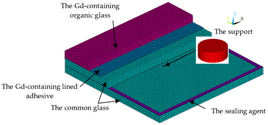
Figure 3.
The finite element model of the neutron shielded vacuum multiple glass.

Table 1.
Material properties of the components employed in the finite-element modelling of vacuum multiple glass.
2.4. Model Validation
In order to verify the correctness of the model, the low and high temperatures were 20 °C and 170 °C. The vacuum thermal conductivity was assumed to be 0.023 Wm−1 K−1. Through simulated calculation, the heat flow was 18.59 W. The heat flux density was 18.59/0.07/0.07 = 3794 W/m2. The simulating equivalent total thermal resistance of the vacuum multiple glass was 0.04 (m2·K)/W. Through theoretical calculation, the thermal resistance of the common glass, organic glass, and vacuum layers were 0.008/0.75 = 0.011, 0.0044/0.2 = 0.022, 0.0002/0.023 = 0.0087 (m2·K)/W, and the theoretical equivalent total thermal resistance of the vacuum multiple glass was 0.0417 (m2·K)/W. The error between the simulating and theoretical results was 4%. So, the finite element model was reasonable.
2.5. Boundary Conditions and Distribution of Neutron Energy Loads
The thermal boundary condition includes the convection heat transfer from the environment, radiation heat from higher temperature side to lower temperature side, neutron heat from the absorption caused by the neutron in the Gd-containing organic glass. In the simulation, the convection heat transfer was assumed to be the environment temperature of 20 °C (lower temperature side) and 170 °C (higher temperature side, which was assumed to be the working temperature). For the radiation heat, the material emissivity of common glass was 0.84. The emissivity of Gd-containing organic glass was not considered in the finite element model. The neutron heat was applied with the exponential function in the Gd-containing organic glass: Wm−3, and the distribution of the neutron heat energy is shown in Figure 4. In the simulation, 105 Wm−3 was assumed to be the maximum neutron heat per element on the top of the Gd-containing organic glass. (m) was the depth from the high-temperature side of the Gd-containing organic glass towards the low-temperature side, as shown in Figure 4. The neutron attenuation index for the Gd-containing organic glass was assumed to be 0.01. It was assumed for the condition named Case 1.
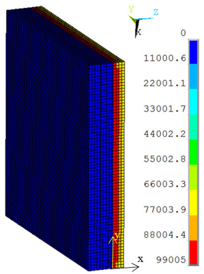
Figure 4.
The distribution of the neutron heat energy.
3. Results and Discussion
3.1. Effect of the Work Temperature on the Temperature Distribution of Vacuum Multiple Glass
The temperature distribution of the thermal models is shown in Figure 5a. The temperature gradient direction of the model was from the high-temperature side to the low-temperature side. Because the vacuum layer exists, the temperature gradient was obvious at the support and the sealing agent around the model. The maximum temperature of the organic glass was predicted to be 98 °C, which occurred at the corners of the model and was lower than its allowable temperature of 120 °C. Results show that the vacuum multiple glass has a good heat insulation and can work in the high temperature of 170 °C, which is higher than the allowable temperature of 120 °C for the organic glass, and the neutron heat: Wm−3. Because the multiple glass did not reach the allowable temperature of 120 °C, the work temperature or the neutron irradiation can be increased.
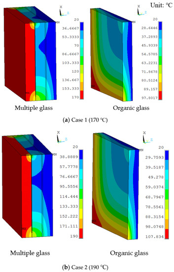
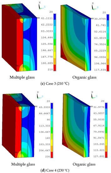
Figure 5.
The temperature distributions of multiple and organic glass for the thermal model at (a) Case 1 (170 °C), (b) Case 2 (190 °C), (c) Case 3 (210 °C), and (d) Case 4 (230 °C).
The working temperatures of 190 °C, 210 °C, 230 °C were applied on the inner surface. The conditions were assumed for Case 2, Case 3, and Case 4. Figure 5 shows different temperature distributions. When the work temperature increased, the temperature of the multiple glass increased. The sealing agent is the key heat transfer element, because the influence of area to the sealing agent is larger than the support area. Also, the maximum temperature of the organic glass occurred close to the sealing agent. The maximum temperature of the organic glass versus the work temperature is shown in Figure 6. This figure shows that by increasing the work temperature, the maximum temperature of the organic glass increased linearly. When the work temperature reached 210 °C, the maximum temperature of the organic glass was predicted to be 118 °C, which is lower than the allowable temperature. If the multiple glass had worked in the temperature of 230 °C, the maximum temperature of the organic glass was predicted to be 128 °C.
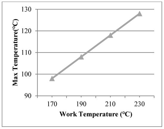
Figure 6.
The maximum temperature of the organic glass versus the work temperature.
To increase the work temperature, the influence of the sealing agent width, view size, and vacuum thermal conductivity on the temperature of the organic glass was studied, because these factors directly affect the heat transmission [23,24].
3.2. Effect of the Sealing Agent Width on the Temperature Distribution of Vacuum Multiple Glass
Sealing agent widths of 1.5 mm, 1.0 mm, and 0.5 mm were used in the finite element model and a work temperature of 230 °C was applied on the inner surfaces. The conditions were assumed for Case 5, Case 6, and Case 7. Figure 7 shows dynamic temperature distributions. When the sealing agent width decreased, the temperature on the left of the sealing agent decreased. The temperature gradient of the edge was controlled by the sealing agent. The maximum temperature of the organic glass versus the sealing agent width is shown in Figure 8, which shows that with a decrease of the sealing agent width, the maximum temperature of the organic glass decreased linearly. When the sealing agent width reached 1.0 mm, the maximum temperature of the organic glass reached 117 °C, which is lower than the allowable temperature of 120 °C. Decreasing the sealing agent width can increase the work temperature of the multiple glass. However, it is different to seal the common glass in the manufacturing process. So, a reasonable sealing agent width should be obtained in the sealing process.
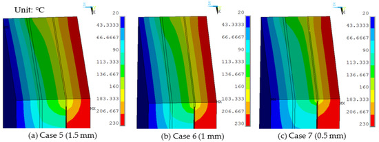
Figure 7.
The temperature distributions of multiple glass for different sealing agent widths.
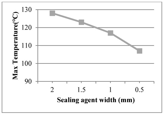
Figure 8.
The maximum temperature of the organic glass versus the sealing agent width.
3.3. Effect of the View Size on the Temperature Distribution of Vacuum Multiple Glass
The view sizes of 50 × 50 mm, 35 × 35 mm, and 20 × 20 mm were utilised in the finite element model, with a work temperature of 230 °C applied on the inner surface. The conditions were assumed for Case 8, Case 9, and Case 10, respectively. Figure 9 shows different temperature distributions. When the view size decreased, the temperature of the multiple glass decreased. Temperature gradient around the view area and support was clearer than other areas. The point of the maximum temperature for the organic glass changed, from the corner of the multiple glass to the support area, when decreasing the view sizes. The maximum temperature of the organic glass versus the view size is shown in Figure 10, which shows that with the decrease in view size, the maximum temperature of the organic glass decreased dramatically. When the view size reached 20 × 20 mm, the maximum temperature of the organic glass reached 44 °C, which is much lower than the allowable temperature of 120 °C. Decreasing the view size can further increase the work temperature of the multiple glass.
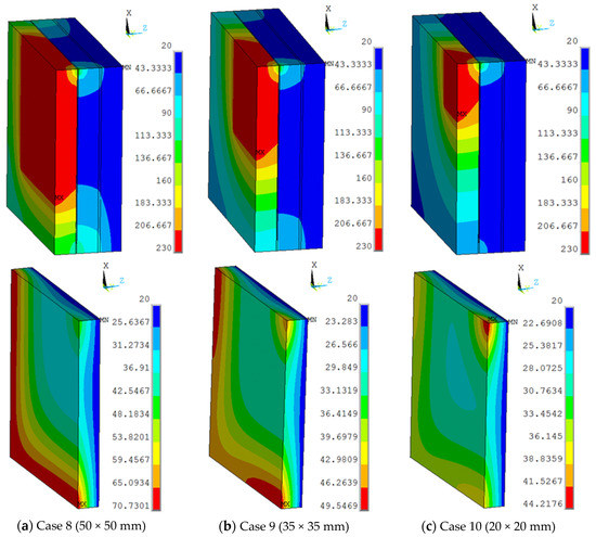
Figure 9.
The maximum temperatures of the organic glass versus the view size.
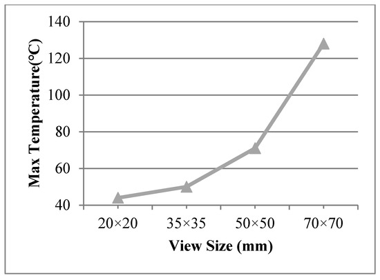
Figure 10.
The max temperature of the organic glass versus the view size.
The view size of 20 × 20 mm was used in the finite element model at work temperatures of 600 °C, 1200 °C, 1580 °C, applied on the inner surfaces, and such conditions were assumed for Case 11, Case 12, and Case 13, respectively. The maximum temperature of the organic glass versus the work temperature (20 × 20 mm) is shown in Figure 11, which shows that with an increase in the work temperature, the max temperature of the organic glass increased linearly. When the work temperature reached 1200 °C, the maximum temperature of the organic glass reached 118 °C, which is lower than the allowable temperature. This is very important for the organic glass working in a high-temperature environment.
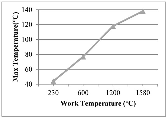
Figure 11.
The max temperature of the organic glass versus the work temperature of the view size (20 × 20 mm).
3.4. Effect of the Vacuum Thermal Conductivity on the Temperature Distribution of Vacuum Multiple Glass
The vacuum thermal conductivity of 0.003 Wm−1 K−1, 0.002 Wm−1 K−1, 0.001 Wm−1 K−1 and the view size of 20 × 20 mm were used in the 3D finite element model at the work temperature of 600 °C applied on the inner surfaces, and the conditions were assumed for Case 14, Case 15, and Case 16. Figure 12 shows different temperature distributions. When the vacuum thermal conductivity decreased, the temperature of the multiple glass decreased. The influence of area on the support became larger, and the maximum temperature of the organic glass increased, which occurred on the support area, as the vacuum thermal conductivity increased. The maximum temperature of the organic glass versus the vacuum thermal conductivity is shown in Figure 13, which shows that with an increase of the vacuum thermal conductivity, the maximum temperature of the organic glass increased linearly. When the vacuum thermal conductivity reached 0.002 Wm−1 K−1, the maximum temperature of the organic glass reached 119 °C, which is lower than the allowable temperature of 120 °C. Decreasing the vacuum thermal conductivity, that is, increasing the vacuum pressure, can increase the work temperature of the multiple glass.
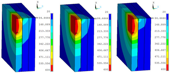
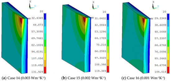
Figure 12.
The temperature distribution of multiple and organic glasses in which vacuum thermal conductivities of 0.003 Wm−1 K−1, 0.002 Wm−1 K−1, 0.001 Wm−1 K−1 and a view size of 20 × 20 mm were used at the work temperature of 600 °C were applied on the inner surfaces and the conditions were assumed for Case 14, Case 15, and Case 16.
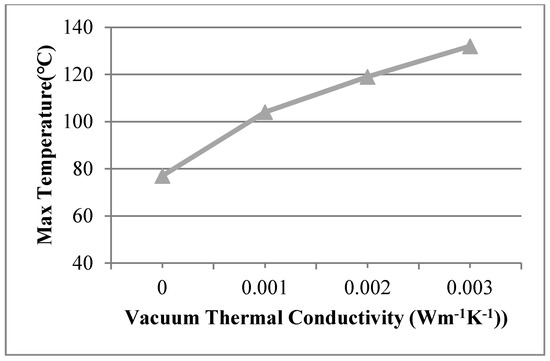
Figure 13.
The maximum temperature of the organic glass versus the vacuum thermal conductivity.
3.5. Overall Discussions
The results are further comparatively discussed in this section. Based on the validated 3D finite element model simulations the vacuum layer between common glasses can make the work temperature of neutron shielding glass increase. The multiple glass had a good heat-shielding performance and it is expected to work in a high-temperature environment. The results implicate that the vacuum layer between the common glasses and the sealing agent width decay with respect to the view size and vacuum thermal conductivity show an increase in the working temperature of the neutron shielding glass. The results from Figure 5 are further discussed here, where it is imperative to mention that the sealing agent contributed to the heat transfer more than the support area of the sample. Thus, the maximum temperature resulted around the sealing area, which further resulted in Figure 6, and it shows a linear relationship between an increase of the work temperature, i.e., 210 °C, and the maximum temperature of the organic glass, predicted to be 118 °C, which is found to be lower than the allowable temperature. The effect of sealing agent width is shown in Figure 7, and it was found that the seal-width was proportional to the temperature on the left side of the sealing agent, and it could be controlled with the sealing agent. This phenomenon was further examined in Figure 8. The view size relationship with temperatures of the multiple glass is shown in Figure 9 and it was found that a decrease in view size decreased the temperature of the multiple glass panes. The maximum temperature of the organic glass versus the view size is shown in Figure 10, and it shows that with the decrease in view size the maximum temperature of the organic glass decreased dramatically. Based on the above work, the result comparison for 16 cases is shown in Table 2. In the table, comparative results are presented that show the effect of different factors on the maximum temperature of the organic glass. As work temperature, view size, and vacuum thermal conductivity increase, the maximum temperature of the organic glass increases. If the work temperature is very high, a smaller view size, sealing agent width, and vacuum thermal conductivity are better. The order of affecting the temperature of the organic glass is as follows: view size > vacuum thermal conductivity > sealing agent width. Based on the work temperature, different values of the view size, vacuum thermal conductivity, and sealing agent width could be selected. The sealing agent width and vacuum thermal conductivity are limited by the manufacturing conditions. The view size is the best method to improve the work temperature.
Table 2.
Results comparison for 16 cases.
4. Conclusions
The temperature distribution characteristics of the vacuum multiple glass was obtained and discussed, and the feasibility of the vacuum multiple glass was verified by numerical calculation. A Gadolinium (Gd)-containing laminate vacuum multiple glass was proposed by using the vacuum insulation method in this paper. A mathematical model was used to analyse the heat transfer process. A 3D finite element model validated by the theoretical calculation was developed to analyse the heat transfer path and numerical simulation of the multiple glass to obtain the temperature distribution and the maximum temperatures of the organic glass in relation to dynamic working temperatures, the sealing agent width, view size, and vacuum thermal conductivity. Following is a summary of conclusions:
- The vacuum layer between common glasses can make the work temperature of neutron shielding glass increase. The multiple glass has good heat-shielding performance and it is expected to work in a high-temperature environment;
- The vacuum layer between the common glasses and the sealing agent width decay with respect to the view size and vacuum thermal conductivity show an increase in the working temperature of the neutron shielding glass;
- The order of affecting the temperature of the organic glass is as follows: view size > vacuum thermal conductivity > sealing agent width. The sealing agent width and vacuum thermal conductivity are limited by the manufacturing conditions. The view size is the best method to improve the work temperature.
Author Contributions
Conceptualization, S.Z., H.M., M.K. and H.M.; methodology, validation, S.Z., H.M., Y.Z. and S.L.; formal analysis, S.Z., M.K. and S.M.; investigation, S.Z., M.K. and Y.Z.; writing—original draft preparation, S.Z., M.K. and S.M.; writing—review and editing, S.M., S.Z. and M.K. All authors have read and agreed to the published version of the manuscript.
Funding
The authors acknowledge the funding support of the National Natural Science Foundation of China (51672241), Project funded by the 14th batch of "Six Talents Peak" High-level Talents (XCL-092), the Province Postdoctoral Foundation of Jiangsu (1501164B), Yangzhou science and technology project (YZ2017275), the Technical Innovation Nurturing Foundation of Yangzhou University (2017CXJ024) and Project funded by China Postdoctoral Science Foundation (2016M600447).
Acknowledgments
This work supported by the research collaboration between London South Bank University, UK, and Yangzhou University. Authors would like to thank the reviewers and editors for their suggestions.
Conflicts of Interest
The authors declare no conflict of interest.
References
- Zhang, X.; Efthimiou, G.; Wang, Y.; Huang, M. Comparisons between a new point kernel-based scheme and the infinite plane source assumption method for radiation calculation of deposited airborne radionuclides from nuclear power plants. J. Environ. Radioact. 2018, 184, 32–45. [Google Scholar] [CrossRef] [PubMed]
- Zhang, S.; Song, Y.; Wang, Z.; Ji, X.; Daly, E.; Kalish, M.; Lu, S.; Du, S.; Liu, X.; Feng, C.; et al. Design of Tokamak ELM Coil Support in High Nuclear Heat Environment. Plasma Sci. Technol. 2014, 16, 300–304. [Google Scholar] [CrossRef]
- Vukolov, K. Radiation effects in window materials for ITER diagnostics. Fusion Eng. Des. 2009, 84, 1961–1963. [Google Scholar] [CrossRef]
- Vukolov, K.; Levin, B. Results of irradiation tests of KU-1 and KS-4V silica glasses as ITER candidate window materials. Fusion Eng. Des. 2003, 66, 861–864. [Google Scholar] [CrossRef]
- Aşkın, A. Gamma and neutron shielding characterizations of the Ag2O–V2O5–MoO3–TeO2 quaternary tellurite glass system with the Geant4 simulation toolkit and Phy-X software. Ceram. Int. 2020, 46, 6046–6051. [Google Scholar] [CrossRef]
- Tekin, H.O.; Kavaz, E.; Altunsoy, E.; Kilicoglu, O.; Agar, O.; Erguzel, T.; Sayyed, M. An extensive investigation on gamma-ray and neutron attenuation parameters of cobalt oxide and nickel oxide substituted bioactive glasses. Ceram. Int. 2019, 45, 9934–9949. [Google Scholar] [CrossRef]
- Kirdsiri, K.; Kaewkhao, J.; Chanthima, N.; Limsuwan, P. Comparative study of silicate glasses containing Bi2O3, PbO and BaO: Radiation shielding and optical properties. Ann. Nucl. Energy 2011, 38, 1438–1441. [Google Scholar] [CrossRef]
- Kaewkhao, J.; Pokaipisit, A.; Limsuwan, P. Study on borate glass system containing with Bi2O3 and BaO for gamma-rays shielding materials: Comparison with PbO. J. Nucl. Mater. 2010, 399, 38–40. [Google Scholar] [CrossRef]
- Sayyed, M.; Qashou, S.I.; Khattari, Z. Radiation shielding competence of newly developed TeO2-WO3 glasses. J. Alloy. Compd. 2017, 696, 632–638. [Google Scholar] [CrossRef]
- El-Moneim, A.A.; El-Mallawany, R. Analysis and prediction for elastic properties of quaternary tellurite Ag2O–V2O5–MoO3–TeO2 and WO3–B2O3–MgO–TeO2 glasses. J. Non-Crystalline Solids 2019, 522, 119580. [Google Scholar] [CrossRef]
- Marple, M.A.; Jesuit, M.; Hung, I.; Gan, Z.; Feller, S.; Sen, S. Structure of TeO2 glass: Results from 2D 125Te NMR spectroscopy. J. Non-Crystalline Solids 2019, 513, 183–190. [Google Scholar] [CrossRef]
- Ab Aziz, S.; El-Mallawany, R.; Hariharan, K.; Rosmawati, S. Effect of Concurrent ZnO Addition and AlF 3 Reduction on the Elastic Properties of Tellurite Based Glass System. Adv. Condens. Matter Phys. 2014, 2014, 1–7. [Google Scholar]
- Sidek, H.A.A.; Rosmawati, S.; Halimah, M.K.; Matori, K.A.; Talib, Z.A. Effect of AlF3 on the Density and Elastic Properties of Zinc Tellurite Glass Systems. Materials 2012, 5, 1361–1372. [Google Scholar] [CrossRef]
- Wang, C.; Wang, C.; He, M.; Li, T.; Yan, C.; Zhang, M. Preparation and Properties of Gd3+-Containing Organic Glass. Chinese. J. Rare Met. 2010, 34, 568–573. [Google Scholar]
- Tang, X.; Chai, H.; Ni, M.; Chen, F.; Chen, D. Neutron Shielding Material with Flame Retardant and Heat Insulation Performance and Its Preparation Method. CN Patent 201510128412.8, 11 July 2017. [Google Scholar]
- Chuntonov, K.; Ivanov, A.O.; Verbitsky, B.; Setina, J. Getters for vacuum insulated glazing. Vacuum 2018, 155, 300–306. [Google Scholar] [CrossRef]
- Fang, Y.; Memon, S.; Peng, J.; Tyrer, M.; Ming, T. Solar thermal performance of two innovative configurations of air-vacuum layered triple glazed windows. Renew. Energy 2020, 150, 167–175. [Google Scholar] [CrossRef]
- Katsura, T.; Memon, S.; Radwan, A.; Nakamura, M.; Nagano, K. Thermal performance analysis of a new structured-core translucent vacuum insulation panel in comparison to vacuum glazing: Experimental and theoretically validated analyses. Sol. Energy 2020, 199, 326–346. [Google Scholar] [CrossRef]
- Memon, S.; Fang, Y.; Eames, P.C. The influence of low-temperature surface induction on evacuation, pump-out hole sealing and thermal performance of composite edge-sealed vacuum insulated glazing. Renew. Energy 2019, 135, 450–464. [Google Scholar] [CrossRef]
- Zhang, S.; Song, Y.; Wang, Z.; Lu, S.; Ji, X.; Du, S.; Liu, X.; Feng, C.; Yang, H.; Wang, S.; et al. Rapid Thermal-Hydraulic Analysis and Design Optimization of ITER Upper ELM Coils. Plasma Sci. Technol. 2014, 16, 978–983. [Google Scholar] [CrossRef]
- Zhang, S.; Song, Y.; Wang, Z.; Du, S.; Ji, X.; Liu, X.; Feng, C.; Yang, H.; Wang, S.; Daly, E.; et al. Structural analysis and optimization for ITER upper ELM coil. Fusion Eng. Des. 2014, 89, 1–5. [Google Scholar] [CrossRef]
- Zhang, W.; Wu, Z.; Liu, Y.-W.; Dong, J.; Yan, X.-W.; Hou, X. Thermal Analysis of Organic Light Emitting Diodes Based on Basic Heat Transfer Theory. Chin. Phys. Lett. 2015, 32, 087201. [Google Scholar] [CrossRef]
- Memon, S.; Farukh, F.; Kandan, K. Effect of Cavity Vacuum Pressure Diminution on Thermal Performance of Triple Vacuum Glazing. Appl. Sci. 2018, 8, 1705. [Google Scholar] [CrossRef]
- Memon, S.; Farukh, F.; Eames, P.C.; Silberschmidt, V.V. A new low-temperature hermetic composite edge seal for the fabrication of triple vacuum glazing. Vacuum 2015, 120, 73–82. [Google Scholar] [CrossRef]


© 2020 by the authors. Licensee MDPI, Basel, Switzerland. This article is an open access article distributed under the terms and conditions of the Creative Commons Attribution (CC BY) license (http://creativecommons.org/licenses/by/4.0/).