Technical Note

Development and Application of Precast Concrete Double Wall System to Improve Productivity of Retaining Wall Construction

1
Department of Architecture, Yeungnam University College, Nam-gu, Daegu 42415, Korea
2
School of Architecture & Civil and Architectural Engineering, Kyungpook National Universit, Buk-gu, Daegu 41566, Korea
3
School of Architecture, Yeungnam University, Gyeongsan-si, Gyeongbuk 38541, Korea
*
Author to whom correspondence should be addressed.
Sustainability 2020, 12(8), 3454; https://doi.org/10.3390/su12083454
Submission received: 31 March 2020 / Revised: 9 April 2020 / Accepted: 10 April 2020 / Published: 23 April 2020

Abstract

:
The construction of most apartment underground parking lots utilizes reinforced concrete (RC) structures composed mainly of rebar work and formwork. RC structures lower construction efficiency and significantly delay the construction because they require a large number of temporary materials and wooden formwork. In this study, a precast concrete double wall (PCDW) system was developed to address the existing problems of RC structures and to improve the productivity of retaining wall construction. PCDW is a precast concrete (PC) wall in which two thin concrete panels are connected parallel to each other with truss-shaped reinforcement between them. PCDW can contribute to securing integrity, reducing the delay in construction, and improving quality. An overall process for the member design and construction stage of the PCDW system was proposed, and its improvement effects were examined regarding various aspects in comparison to the RC method.

1. Introduction

Recent construction projects have actively used various improved methods to shorten the construction period and improve efficiency. However, the construction of most apartment underground parking lots utilizes reinforced concrete (RC) structures mainly composed of rebar work and formwork [1]. The construction of these parking lots affects the entire construction period of a project. Their construction must be completed early because underground parking lots are used as rebar workplaces for the construction of ground parts, and as storage yards for building finishing materials. However, RC structures have low construction efficiency and, most significantly, delay construction because they require temporary materials in large quantities and wooden formwork [2,3]. Therefore, there has been a growing need for measures to improve underground parking lot structure systems capable of addressing these problems. Employment of precast concrete (PC) method has been gradually increasing for this purpose [4,5]. The PC method enables efficient construction management, such as shortening the construction period and saving labor cost, because high-quality standardized members are produced in factories and assembled at sites [6,7]. It has also become advanced and has been widely used since its development in the mid-1800s owing to its higher constructability and productivity than the RC method [8,9,10]. However, for the construction of most retaining walls, the PC method is replaced with a combination of PC and RC processes resulting in frequent defects due to the occurrence of various cracks at the joints [11]. Furthermore, studies have been conducted on various methods, including joining methods and performance verification, to be applied to special members involving difficult construction such as apartment framework, balconies, stairs, railings, and underground parking lots [12,13,14,15,16].
Ji and Choi [17] researched a method of manufacturing an integrated wall by installing a link beam on the inside and outside walls of a PC and applied the method to common and reservoir walls. Furthermore, Park [18] proposed a method of forming a wall by fastening a PC panel and a panel with anchor bolts, while Oh et al. [19] conducted a study to confirm the advantages of the corresponding wall in the area of air shortening. In addition, Yang et al. [20] produced a double-synthetic precast wall with a double T-shaped PC panel facing each other to secure the economy and safety of the basement wall construction and then conducted experiments on the bending and shear behavior of the specimen. The method of pouring topping concrete after PC installation was applied also to slabs and columns. For slabs, double tee slabs, hollow slabs, and half PC slabs were identified [21]. In the case of columns, the hollowed precast concrete (HPC) column was produced by centrifugally molding a hollow PC part in the factory and pouring concrete into the field [22]. It was confirmed that the difference in performance between the existing RC structure and the HPC column was applicable to the seismic structure system. In addition, Roh and Hashlamon [23] and Kim and Kang [24] presented a development for piers and bridge columns through pouring concrete in the hollow precast and further conducted a study to analyze the seismic performance. In the case of a typical PC method, stress discontinuity due to inter-component disconnection is formed at the joint; thus, it is not easy to achieve the same performance as that of the RC structure. Furthermore, such a method may fail if the external wall support is insufficient, and there is risk of a safety accident. Therefore, the composite method of combining PC and topping concrete is increasing [17].
This study intends to present an application method for the precast concrete double wall (PCDW) system that is more suitable for retaining wall construction than the existing method. PCDW refers to a PC wall in which two thin concrete panels are connected parallel to each other with a truss-shaped reinforcement between them. As PCDW is connected to adjacent panels by pouring concrete between the panels, the completed wall achieves integrity. Furthermore, shortening of the construction period, quality management, and waste reduction can also be expected.
In this study, important factors in the processes of the design, production, installation, and completion of the PCDW system are examined to propose measures to activate the method. Further, an overall process for the member design and construction stage of the PCDW system was proposed, and its improvement effects were examined by applying it to actual construction sites. During the member design stage, the main examination items were analyzed considering the mechanical behavior of the joints, and appropriate member connection and joining methods were derived. Therefore, measures of securing the integrity of the joints of each PCDW member with vertical, corner, horizontal, and foundation concrete were presented. Furthermore, a pull-out test of headed bar was conducted in this study to evaluate the connection performance of the vertical and horizontal joints of PCDW. PCDW should resist the lateral pressure of concrete during the pouring process and curing period. Hence, the PCDW member design was examined based on the criteria suggested by the South Korean Building Code (KBC2009) and the Structural Design Standards and Commentary for Precast Concrete Prefabricated Buildings (1992). During the PCDW construction stage, an overall construction process, from the installation process to the pouring of concrete into the PCDW void, was established and verified through a case study. The benefits of the PCDW system were then examined based on various aspects via a comparison with the reinforced concrete (RC) method, which was applied to the construction of most apartment underground parking lots.

2. Development of Precast Concrete Double Wall System

2.1. Securing the Integrity of PCDW Joints

Retaining wall construction through the PCDW system requires appropriate geometry and reinforcement of the joints. Examination of the retaining wall construction cases that used RC structures showed that the retaining wall thickness was in the range of 400–600 mm. In addition, the vertical and horizontal rebars of walls were reinforced with wall-rebar ratio in the range of 0.002–0.007 to resist external forces such as earth pressure. In some cases, the upper and lower parts of walls required shear reinforcement. This study aims to propose the geometry, details, and reinforcement method of panels for the retaining walls of a structure based on the commonly used 400 mm wall thickness. In a PCDW system, two thin concrete panels are connected parallel to each other. Therefore, to secure the integrity of the panels, lattice bars were fabricated and placed at the center of these panels as shown in Figure 1.

2.2. PCDW Joint Configuration

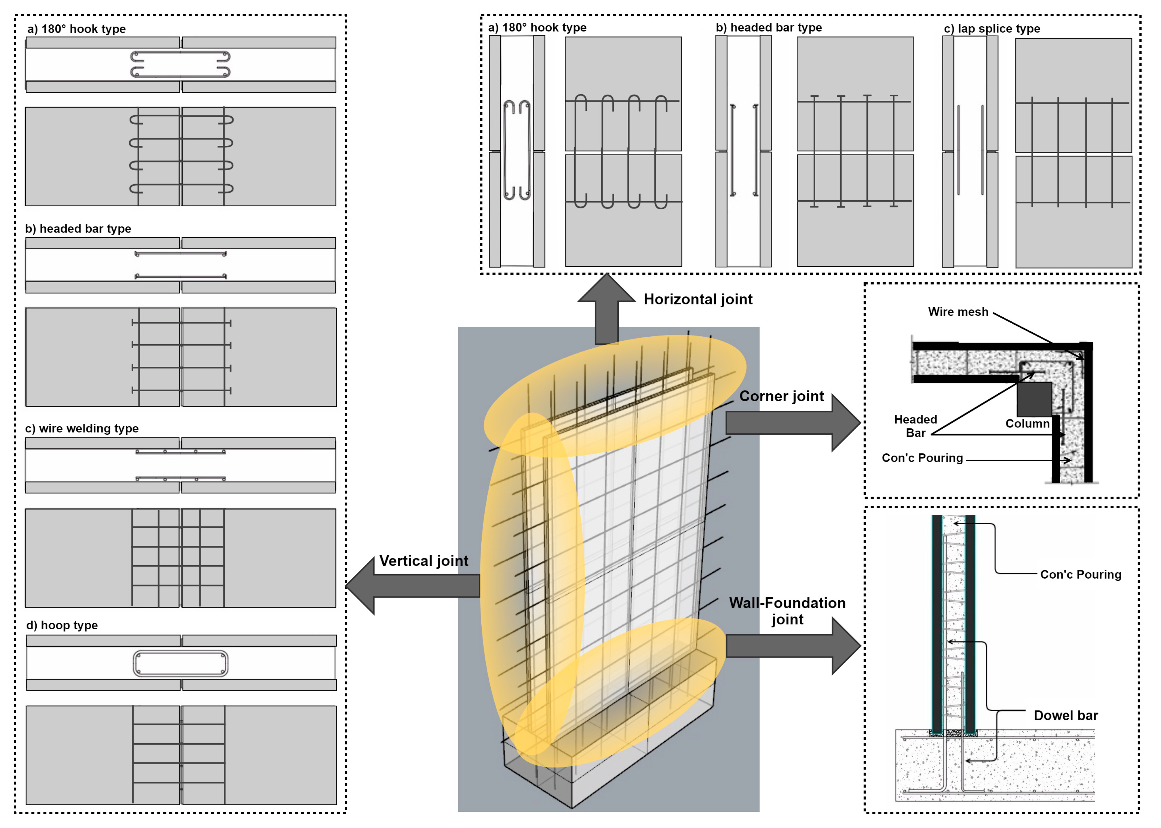
The PCDW system requires panel-to-panel joints with vertical joints to connect the left and right panels, horizontal joints to connect the upper and lower panels, and wall-foundation joints to connect the panels and foundation concrete. The joints require appropriate reinforcement to achieve integrated behavior against the stress and deformation caused by out-of-plane loading applied to the walls on both sides.
When the PCDW system is applied to the basement, it is necessary for the vertical joints to secure resistance performance against the bending moment through separate resistance mechanisms for safety against loads such as earth pressure. To address this problem, connection using standard hook (180° hook type) rebars, headed bars, or wire welding can be used. For the horizontal joints between the upper and lower walls composed of PCDW panels, sufficient resistance performance is required against the bending moment and shear force that may occur at the joints under vertical forces such as earth and hydraulic pressures. However, as the vertical wire welding applied to panels is discontinuous, separate resources are required at the joints to resist the bending moment. Connection using standard hook rebars or headed bars or lap splice using straight rebars can be used for the purpose. The joints between PCDW and the foundation can be constructed with concrete after assembling the dowel bars in the cast-in-place concrete foundation plate or PC foundation plate to be placed in the void of the PCDW. As the retaining walls of a structure are subjected to large wall end moment and shear force due to loads such as earth pressure, the joints between PCDW and the foundation can sufficiently resist such stress. In this instance, the dowel bars can provide the tensile force due to the bending moment, and the required shear strength can be obtained by the concrete filling the void of PCDW and the vertically arranged lattice bars. Figure 2 shows the lattice bar types and joining methods available for each joint.

2.3. Headed Bar Performance Evaluation

Although the headed bars used at PCDW joints may vary in size and geometry, appropriate guidelines are not sufficient in South Korea. Therefore, analysis is required for specific geometry. Hence, a pull-out test was conducted in this study to evaluate the connection performances of the vertical and horizontal joints of PCDW. In the pull-out test, the tensile strength and anchorage capacity of the ten test pieces of the developed headed bar were evaluated by burying them in concrete and applying pull-out loads (Figure 3).
The specified strength of the concrete used for the test pieces was 24 MPa, and the size of the test pieces was ∅ 100 × 200 mm. Tests on the compressive strength of concrete were conducted on the 7th, 14th, and 28th days after the fabrication of the test pieces. The strength of concrete was determined by averaging the values obtained from three test pieces. For the fabrication of the headed bar, screw threads were machined at the end of the D13 (Deformed bar, Yield Strength = 400 MPa, Unit weight = 0.995 kg/m) deformed bar and a head was attached.
The results of the pull-out test on the headed bar showed that the ten test pieces did not exhibit any cracks or fractures in concrete during the pull-out test, and most of them failed at the position of the strain measuring gauge attached in the middle of the deformed bar (Table 1). Figure 4 shows the load-strain relationship of the pull-out test. The average of the maximum loads was 73.8 kN, which was higher than the yield strength. It was confirmed that failure occurred in a plastic deformation state that exceeded the yield strain. This indicates that the developed headed bar is suitable for securing the yield strength of rebars. However, machining the screw heads reduces the cross-sectional area of the deformed bar of the headed bar by approximately 10%. Hence, it is necessary to set 90% of the cross-sectional area of the deformed bar as the effective cross-sectional area for the headed bar that is to be used as a joint reinforcement.

3. PCDW Design through the Examination of Lateral Pressure and Bending

3.1. PCDW Member Design

For PCDW, cast-in-place concrete poured into the space between PC panels. Therefore, PCDW should resist the lateral pressure of concrete during the pouring process and the curing period. The lateral pressure is determined by the unit weight, pouring height, pouring speed, and temperature. Detailed examination of pouring plans and partition height calculation is required before the concrete pouring. In this study, the PCDW member design was examined based on the criteria suggested by the South Korean Building Code (KBC2009) and the Structural Design Standards and Commentary for Precast Concrete Prefabricated Buildings (1992). Figure 5 shows the PCDW member design conditions.

3.2. Examination of Lpressure and Bending

Equations (1)–(3) is the lateral pressure calculation formula for concrete poured by general internal vibro-compaction for which the concrete slump is ≤175 mm and the depth is ≤1.2 m. The equation can be used for walls when the pouring speed is <2.1 m/h and the pouring height is <4.2 m. In the equation, “p” is the horizontal pressure (Kn/m2), “R” is the pouring speed (m/h), and “T” is the concrete temperature in the formwork (°C). “Cw” is the unit weight factor with a value of 1 corresponding to the unit weight ranging from 22.5 to 24 N/m3, which was used based on the South Korean Building Code (KBC2009). “Cc” is the chemical additive factor with a value of 1 corresponding to the type 1, 2, and 3 cement of KS L 5201 that uses no retarder.
p = C w C c 7.2 + 790 R T + 18
C w = C c = 1.0
p = 7.2 + 790 × 2 35 + 18 = 37.1 kN / m 2
The flexural strength of PCDW was calculated using a panel thickness of 60 mm and a lattice bar spacing of 500 mm. Equations (4)–(7) shows the results of the working load moment ( M ), bending stress ( σ ), allowable tensile stress under crack width limitation ( f t ), and flexural reinforcement ( M u ). Equations (8)–(12) shows the results when the inside of the PCDW panel was reinforced with wire welding (   8 × 150 × 150 (fy = 400 MPa)).
M = p L 2 8 = 37.1 ( 0.5 ) 2 8 = 1.159   km
σ = M Z = M b h 2 / 6 = 6 ( 1.159 ) 1 ( 0.06 ) 2 = 1931.7   kN m 2 = 1.9   MPa
f t = 0.63 f c k = 0.63 35 = 3.73   MPa > 1.4   MPa o . k .
M u = 1.2 × 1.159 = 1.39   kNm
A s = 333   mm 2 / m
a = A s f y 0.85 f c k b = 333 × 400 0.85 × 35 × 1000 = 4.5   mm
d = 60 2 = 30   mm
M n = A s f y ( d a 2 ) = 0.85 × 333 × 400 × ( 30 4.5 2 ) × 10 6
= 3.14   kNm > 1.39   kNm o . k .
Equations (13)–(16) shows the shear performance based on the PCDW lateral pressure examination results. “ V u ” is the ultimate shear force in the cross section, and “ ” is the strength reduction factor.
V = p L 2 = 37.1 ( 0.5 ) 2 = 9.275   kN
V u = 1.2 × 9.275 = 11.13   kN
V n = ( 1 6 ) f c k b w d = 0.75 ( 1 6 ) 35 ( 1000 ) ( 30 ) ( 10 3 )
= 22.19   kN > 11.13   kN o . k .
Equations (17)–(19) shows the shear connector examination results, and the safety factor (n) according to the tensile force ( T n ) and working load ( T u ) of the shear connector (lattice bar 10 at 500, f y = 400 MPa). Equations (20) and (21) shows the deflection examination ( δ ) results for the lateral pressure of PCDW.
T n = A s f y = 0.85 × 71 × 400 = 24.1   kN
T u = 1.2 × p × L × @ T i e b a r = 1.2 × 37.1 × 0.5 × 0.5 = 11.13   kN
n = 24.1 / 11.13 = 2.16 > 2 o . k .
δ = 5 p L 4 384 B I = 5 P L 4 384 ( 6500 f c k 3 ) ( b h 3 12 ) = 5 ( 37.1 ) ( 500 ) 4 384 ( 8500 35 3 ) ( 1000 ) ( 60 ) 3 12
= 0.06   mm < L 360 ( = 1.39   mm ) o . k .

4. Field Application of the PCDW System

4.1. PCDW Construction Sequence

The case study site for this study was a new apartment construction site, which included six buildings (two basement stories and 25 ground stories). The PCDW system was applied to the retaining walls of underground parking lots, and a total of 100 units were used. Figure 6 shows the layout of the site and the installation plan by section and the PCDW construction sequence.
Figure 7 shows the main construction process of PCDW, and its contents are as follows:
  • Before the installation of PCDW, foundation rebars and the anchorage rebars of PCDW are placed and the recess metal lath for pad mortar pouring are installed at the top for accurate connection between PCDW and the foundation. In this case, the cover thickness of the upper part of the foundation must be approximately 50 mm.
  • Two liner shims are installed on the floor per PCDW system. After examination of the liner shim level, pad mortar is applied in two rows and PCDW is installed on top of them.
  • After the assembly of PCDW, its vertical state is examined using an inclinometer. Two or more prop supports are firmly installed to prevent any gaps or misalignment.
  • After inspection of the assembly state, the reinforced state, and the installation of the other parts, concrete is poured in the PCDW void. Before concrete pouring, the inside is cleaned to remove foreign substances, and water is sprayed to keep the inside wet. In addition, compaction is performed using a rod-type vibrator or a form vibrator to prevent poor-compacted concrete, and then PCDW is assembled and prop supports are installed. After the assembly of the PCDW system, the assembly accuracy is inspected. Table 2 shows the inspection methods and the judgment criterion.

4.2. Analysis of the Effect of PCDW System Application

In this study, the actual effects of the application of the PCDW system, which improved the existing PC method, were examined on the basis of various aspects via a comparison with the RC method. Table 3 shows the effects of the PCDW system that were verified through the case study.
The actual cost comparison was calculated based on the material and labor costs. The material cost of the RC method consisted of the concrete, form rebar, grinding, and plastering works. Based on this, labor costs were calculated according to the number of workers required to perform each task. The material cost of the PCDW method consisted of the PC panels and concrete poured into the PCDW void, and the labor cost was calculated according to the number of workers required for each work performance. The PCDW method was able to reduce the cost by omitting formwork and rebar work compared with the RC method, but the PC panel cost was added. As a result, the cost difference between the two methods was approximately 1%. In addition, both methods required lifting equipment, but no additional cost was required, as T/C had already been installed at the site.
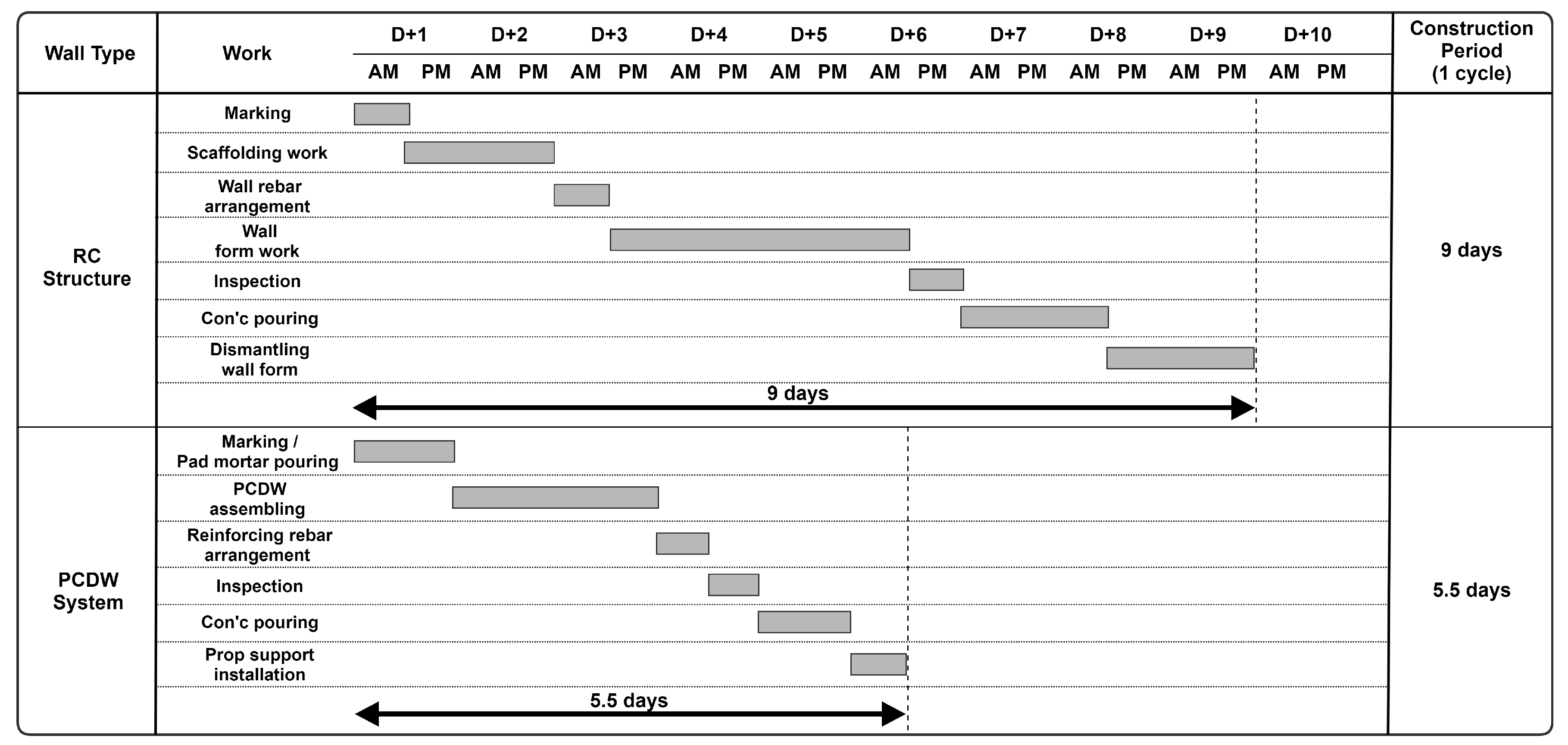
The primary benefit of the PCDW system compared to the existing RC method is the shortening of the construction period. As the PCDW system is 100% produced in factories for on-site installation, it does not need formwork for concrete pouring, which requires a considerable amount of time as in the case of the RC method. It can also reduce the framing construction period by approximately 40%. Figure 8 compares the progress schedule of the RC method with that of the PCDW system to examine the construction period of apartment retaining walls (pillar + beam + wall). The progress schedules show the number of days required for each process for a 30.8 m × 4 m (one floor with 4 spans) floor size, and it was calculated based on one formwork team (seven persons).

5. Conclusions

This study proposed an overall process for applying the precast concrete double wall (PCDW) system, which addressed the drawbacks of the precast concrete (PC) method, to actual construction sites. Particularly, measures to secure the integrity of the joints of each PCDW member with vertical, corner, horizontal, and foundation concrete were presented. Member design was performed considering concrete lateral pressure, and pouring plans and partition height calculation were examined in detail. In addition, the benefits of the PCDW system were examined based on various aspects via a comparison with the reinforced concrete (RC) method, which has been applied to the construction of most apartment underground parking lots.
The currently applied PC method has the disadvantages that the PC and RC processes are mixed, workability is poor, and construction management is cumbersome because only the inner columns, beams, and slabs are applied, except for the retaining walls. Therefore, the introduction of the PCDW system is expected to simplify construction management and improve the constructability because PC can be used for the entire framework of apartment underground parking lots. In addition, it is expected to enable active improvements to the construction site situation, in which the lack of skilled workers, such as form and reinforcement workers, worsens the situation. However, as the application of the PCDW system was limited to the external walls of apartment underground parking lots in this study, additional case studies are required for its application to entire buildings. Furthermore, the examination of economic efficiency presents limitations because only the construction cost of basement framing construction was identified. Although the shortening of the construction period reduces the total construction cost due to the reduction of indirect cost, construction cost analysis is required considering other elements in addition to the cost of basement framing construction analyzed in this study.

Author Contributions

In this paper, S.K. (Seungho Kim) designed the research framework and wrote the paper. D.-E.L. and Y.K. collected and analyzed the data. S.K. (Sangyong Kim) conceived the methodology and developed the ideas. All authors have read and agreed to the published version of the manuscript.

Funding

This work was supported by the National Research Foundation of Korea (NRF) grant funded by the Korea government (MSIT) (No. NRF-2018R1A5A1025137).

Conflicts of Interest

The authors declare no conflict of interest.

References

  1. Kim, S.Y.; Lee, B.S.; Park, K.Y.; Lee, S.B.; Yoon, Y.H. Foreign parking structures and practical using method of PC system for the domestic underground parking structures. Mag. Korea Concr. Inst. 2008, 20, 34–40. [Google Scholar] [CrossRef]
  2. Hwang, J.H. Development of Integrated Management Process for Precast Concrete Construction Method based on BIM. Master’s Thesis, School of Urban Science, University of Seoul, Seoul, Korea, 2019. [Google Scholar]
  3. Qin, Y.; Shu, G.P.; Zhou, G.G.; Han, J.H. Compressive behavior of double skin composite wall with different plate thicknesses. J. Constr. Steel Res. 2017, 157, 297–313. [Google Scholar] [CrossRef]
  4. Chai, S.; Guo, T.; Chen, Z.; Jun, Y. Monitoring and simulation of long-term performance of precast concrete segmental box girders with dry joints. J. Bridge Eng. 2019, 24, 04019043. [Google Scholar] [CrossRef]
  5. Park, J.H.; Choi, J.W.; Jang, Y.J.; Park, S.K.; Hong, S.N. An experimental and analytical study on the deflection behavior of precast concrete beams with joints. Appl. Sci. 2017, 7, 1198. [Google Scholar] [CrossRef] [Green Version]
  6. Chen, S.; Feng, K.; Lu, W. A Simulation-Based optimisation for contractors in precast concrete projects. In 10th Nordic Conference on Construction Economics and Organization; Emerald Publishing Limited: Bingley, UK, 2019; Volume 2, pp. 137–145. [Google Scholar] [CrossRef]
  7. Zhai, X.; Reed, R.; Mills, A. Factors impeding the offsite production of housing construction in China: An investigation of current practice. Constr. Manag. Econ. 2014, 32, 40–52. [Google Scholar] [CrossRef]
  8. Ahmad, S.; Soetanto, R.; Goodier, C.I. Lean approach in precast concrete component production. Built Environ. Proj. Asset Manag. 2019, 9, 457–470. [Google Scholar] [CrossRef] [Green Version]
  9. Kang, T.S. Precast concrete construction of SAMPYO engineering & construction LTD, R&D institute. Mag. Korea Concr. Inst. 2019, 25, 46–49. [Google Scholar]
  10. Kim, S.Y.; Yoon, Y.H.; Park, K.Y.; Lee, B.S.; PC Council. A Research for Practical Using Method of PC Structural System for the Underground Parking Garage in an Apartment Housing Site. Korea National Housing Corporation Housing & Urban Research Institute. 2006. Available online: https://dl.nanet.go.kr/SearchDetailView.do?cn=MONO1200827476 (accessed on 9 April 2020).
  11. Kim, H.D.; Lee, S.S.; Park, K.S.; Bae, K.W. A study on plant certification program for precast concrete products. KSMI 2014, 18, 131–138. [Google Scholar] [CrossRef] [Green Version]
  12. Augusto, T.; Mounir, K.; Melo, A.M. A cost optimization-based design of precast concrete floors using genetic algorithms. Autom. Constr. 2012, 22, 348–356. [Google Scholar] [CrossRef]
  13. Castilho, V.C.; Lima, M.C.V. Comparative costs of the production, transport and assembly stages of prestressed precast slabs using genetic algorithms. IJOCE 2012, 2, 407–422. [Google Scholar]
  14. Ko, C.H. Material transshipment for precast fabrication. J. Constr. Eng. Manag. 2013, 19, 335–347. [Google Scholar] [CrossRef] [Green Version]
  15. Sacks, R.; Eastman, C.M.; Lee, G. Parametric 3D modeling in building construction with examples from precast concrete. Autom. Constr. 2004, 13, 291–312. [Google Scholar] [CrossRef]
  16. Suh, J.I.; Park, H.G.; Hwang, H.J.; Im, J.H.; Kim, Y.N. Development of PC double wall for staircase construction. J. Korea Inst. Build. Constr. 2014, 14, 571–581. [Google Scholar] [CrossRef] [Green Version]
  17. Ji, K.H.; Choi, B.J. Improvement of Underground Wall Design and Construction Safety Using Mega Double Wall Construction Method. J. Korean Soc. Hazard Mitig. 2019, 19, 1–12. [Google Scholar] [CrossRef]
  18. Park, K.M. A Study on the Production and Construction of Precast Concrete Walls. Master’s Thesis, Kyonggi University, Suwon, Korea, 2017. [Google Scholar]
  19. Oh, S.Y.; Hong, S.Y.; Park, K.M. A study on the site work of precast concrete double composite wall. Proc. Korea Concr. Inst. 2017, 29, 407–408. [Google Scholar]
  20. Yang, H.M.; Han, S.J.; Lee, S.H.; Choi, S.H.; Chung, J.H.; Kim, K.S. Out of plane behavior of double composite PC walls. Proc. Korea Concr. Inst. 2018, 30, 149–150. [Google Scholar]
  21. Kim, J.S.; Jung, J.W.; Lee, K.H.; Ahn, J.M. Recent domestic precast concrete slab technologies. Mag. Korea Concr. Inst. 2004, 16, 16–19. [Google Scholar] [CrossRef]
  22. Seo, S.Y.; Yoon, S.J.; Lee, W.J. Evaluation of structural performance the hollow PC column joint subjected to cyclic lateral load. J. Korea Concr. Inst. 2008, 20, 335–343. [Google Scholar] [CrossRef] [Green Version]
  23. Roh, H.S.; Hashlamon, I.H. Hysteretic model and seismic response of partial precast concrete piers with cast-in-place for base and outside of hollow cross section. Proc. Korea Concr. Inst. 2016, 28, 123–124. Available online: http://www.riss.kr/link?id=A101902151 (accessed on 9 April 2020).
  24. Kim, T.H.; Kang, H.T. Seismic performance assessment of hollow circular reinforced concrete bridge columns with confinement steel. J. Earthq. Eng. Soc. Korea 2012, 16, 13–25. [Google Scholar] [CrossRef]
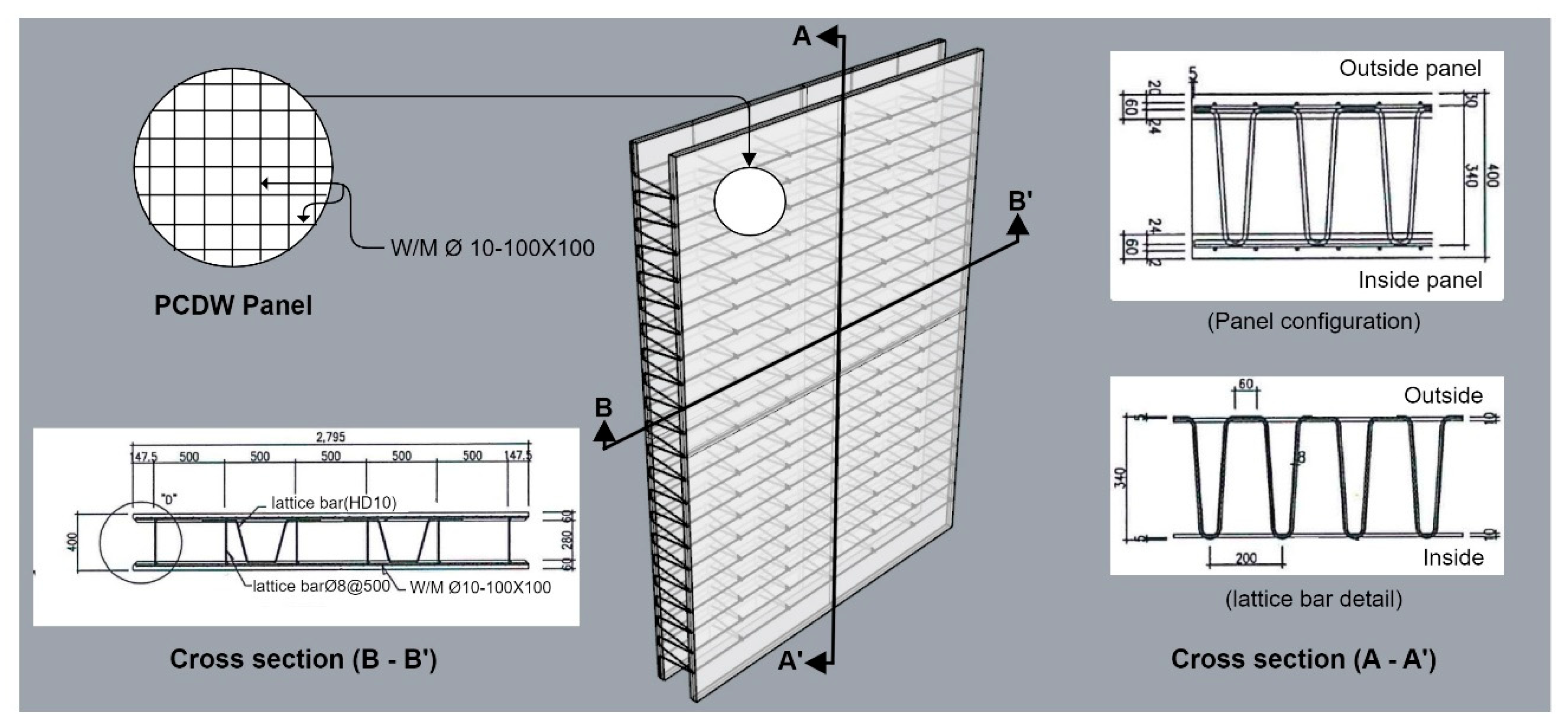
Figure 1. Panel configuration and lattice bar details of the precast concrete double wall (PCDW) system.
Sustainability 12 03454 g001
Figure 2. Joining methods for each PCDW joint.
Sustainability 12 03454 g002
Figure 3. Headed bar conduct analysis.
Sustainability 12 03454 g003
Figure 4. Load-strain relationship of the headed bar.
Sustainability 12 03454 g004
Figure 5. PCDW member design conditions.
Sustainability 12 03454 g005
Figure 6. PCDW construction plan and flowchart.
Sustainability 12 03454 g006
Figure 7. Main construction process of PCDW.
Sustainability 12 03454 g007
Figure 8. Comparison of basement framing construction periods.
Sustainability 12 03454 g008
Table 1. Results of the pull-out test on the headed bar.
Basic Data of Specimenfck
(MPa)
fy
(MPa)
hef (mm)D
(mm)
A
(mm)
Additional Information
44.751621030127
T y A s × f y = 127 × 516 = 65.5 (kN)Yield strength of the headed bar
N s a A s × f u = 127 × 640 = 81.3 (kN)Rupture Strength of the headed bar
N c b A N c A N c o φ c d φ c φ c p N b = 254.3 (kN)Concrete Cone Breakout
specimen-173.3(kN)yield and fracture
specimen-273.6(kN)yield and fracture
specimen-377.6(kN)yield and fracture
specimen-468.2(kN)yield and fracture
specimen-576.1(kN)yield and fracture
specimen-674.9(kN)yield and fracture
specimen-773.6(kN)yield and fracture
specimen-871.4(kN)yield and fracture
specimen-970.7(kN)yield and fracture
specimen-1078.7(kN)yield and fracture
Overall average73.8(kN)
Standard deviation3.2(kN)
Coefficient of variation4.3(%)
Table 2. Assembly accuracy inspection criterion for the PCDW system.
CategoryTest MethodFrequencyJudgment Criterion
PCDW systemInstallation positionThe difference from the reference line marked on the floor is measured using a steel rulerAfter assembly±5 mm
or less
InclinationMeasured using a plumb or a slope scale
Ceiling heightMeasured using a level
Table 3. Comparison between the RC and PCDW methods.
CategoryRCPCDWRemark
Construction cost100%99%1% reduction
Construction/
safety
- Formwork for concrete pouring requires a considerable amount of time
- Work safety must be examined for pouring
- Site work can be simplified without formwork
- Construction safety can be secured without external scaffold and temporary facilities
Construction period100%60%40% reduction
Quality- Quality significantly varies depending on the type and condition of formwork- Factory production ensures excellent quality
Others- No lifting equipment required
- Easy connection to the bottom wall rebars
- Labor-intensive structure, lack of skilled workers
- Highly difficult formwork
- Eco-friendly because of on-site waste reduction
- Member size limited by the transport and lifting conditions
- Constructible regardless of the climate
- Increased durability due to steam curing