1. Introduction
The building sector accounts for around one-third of global greenhouse gas emissions and more than 40% of global energy demand [
1]. In the United Arab Emirates (UAE), buildings consume about 90% of the total electricity used in the country [
2]. Abu Dhabi, the capital of the UAE, experienced a sharp increase in its energy consumption from 65,000 GWh to 110,000 GWh between 2010 to 2018, with a monotonic increase in installed electrical power capacity from 71,000 GWh to 119,000 GWh (
Figure 1) [
3]. About 32% of the building sector’s electricity consumption is attributed to air-conditioning systems worldwide [
4,
5]. Comparatively, over 70% of the electricity is used to meet the air-cooling demand in Abu Dhabi, given its hot climatic conditions [
6]. Recently, the electric power consumption has been closely approaching the power production capacity, leaving an excess production of only 9100 GWh in 2018, as shown in
Figure 1 [
3]. The production–consumption data, on one hand, show little idle running, but on the other hand, increase the risk of reduced surplus at peak time. The increasing energy consumption may further reduce the demand–supply gap and the power network may be at risk of peak-time power shortage. In added power production capacity, several parallel attempts are required on demand-side management to reduce energy consumption to maintain power grid stability.
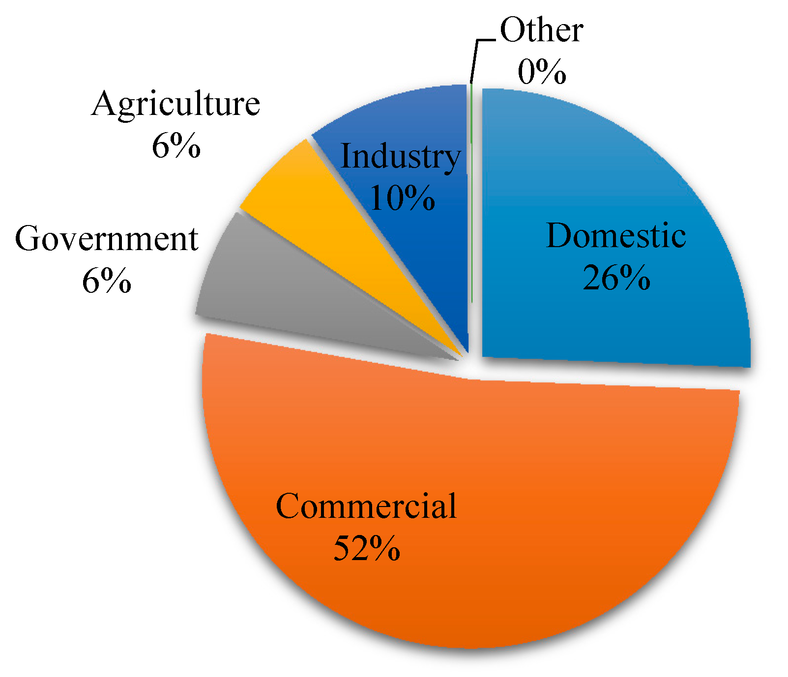
The fact that the domestic and commercial building sector accounts for 78% of the total electrical energy consumption in the UAE [
7], as shown in
Figure 2, naturally draws a focus to adopting measures to reduce building energy consumption and looking for an alternative, less energy-consuming building services system. In this line, the UAE is aiming to amplify power generation from clean energy to 30% by 2030, where a sizable 25% to 30% of its electricity needs will be from both nuclear and solar energy [
8]. The latter is facilitated by the abundance of solar radiation, with an annual average global solar irradiance is 6 kW h/m
2/day [
9] Throughout the year, the outdoor relative humidity remains above 60% in Abu Dhabi, which eventually leads a higher yearly energy consumption of 57% in dehumidification, compared to 43% in cooling in a specific building [
10]. In a bid for a less energy-intensive system adaptation in buildings, an alternative way of dehumidification system remains relatively unexplored in UAE.
A solar-assisted desiccant dehumidification system offers an advantage over electrical heating-based desiccant systems in the UAE, having a higher solar radiation flux of 2370 kWh/m
2-year on an inclined plane [
5,
12]. The conventional method of dehumidification relies on employing condensing coils to drain humidity from cooling air streams consuming on average 30% cooling energy consumption in UAE [
6,
13]. The energy-intensive dehumidification system needs to be replaced by an energy-efficient dehumidification system specifically suited for the hot climate of the UAE [
14]. The solar-assisted dehumidification systems have been proven effective for hot and humid climates for large-scale building air conditioning applications [
15]. Zhao et al. [
16] led an experimental investigation on a desiccant dehumidification unit using silica gel coating and found that the unit can dehumidify 100% fresh air under mild humidity loads. Hao et al. [
17] investigated the performance of a solar-assisted desiccant dehumidification system coupled with a chilled roof and displacement ventilation and reported up to 8% energy savings compared to a condensing coils-based dehumidification system. Solar-assisted desiccant dehumidification systems were further improved by employing nanofluids for enhanced heat transfer applied in a greenhouse buildings in Saudi Arabia [
18]. In another study done in Saudi Arabia, the performance of an integrated evaporative-cooled window with a desiccant dehumidification system combined with a photovoltaic/thermal (PV/t) system was examined [
19]. The hybrid system showed a reduction in the inner window temperature by 5 °C to 7 °C, resulting in an 11% decrease of the total cooling load during the summer months. In another study, solid desiccant dehumidification employing photovoltaic thermal (PV/T) for thermal energy supply with Maisotsenko coolers was experimentally evaluated in the UAE, employing a PV/T with a coverage area of 681.0 m
2, which provided the 36.5% thermal energy required for desiccant regeneration, thus saving 139.7 MWh per year electrical energy [
20]. The solar-assisted dehumidification systems have been studied in Italy and were found effective to provide environmentally friendly comfort conditions [
21]. These brief literature findings provide insight into the technical feasibility of the desiccant dehumidification system in hot climate zones. However, the system has not been studied comprehensively in terms of influencing operating parameters. The previous research article highlights the need for more comprehensive studies into the solar-assisted dehumidification system specific to the UAE climate. The current article starts investigating certain aspects of solar-assisted dehumidification in the UAE and will generate further insight into the topic through more research in the future.
Thus, the current article aimed to investigate the possibilities of optimizing operating parameters to determine the most feasible operational modes of the solar-assisted desiccant dehumidification system in the context of the UAE in specific and in the hot and humid climatic zone in general. The TRNSYS simulation program was employed to model the system leading to an assessment of energy and economic savings of the proposed system.
1.1. Building Details
A school building located in Abu Dhabi and compliant with Estidama, the green building code applicable in the UAE was selected to be examined for this research. The school has an existing rooftop solar thermal collector array covering 46 m2 roof space. The array comprises 18 solar thermal collectors with a 2.5 m2 aperture area of each collector connected to a central hot water storage tank to provide hot water for the swimming pool, kitchen, and showers. The collector system produces 117,760 kWh thermal energy, thus saving 4.5% of building annual energy demand. Although the solar thermal collector is very efficient during wintertime serving hot water needs, the system remains idle during summer months (April–October) as the hot water demand during this time drops to nil. To extend the use of the system all-year-round, the authors came up with the idea of connecting the solar thermal system to a desiccant dehumidification system to provide the heat required for desiccant regeneration in the summer months, to lower the energy consumption due to air conditioning. The scope of the work was defined by simulation studies involving system capacity assessment and optimization in the climatic conditions of the UAE.
The sprawling school building comprises two floors with a 14,694 m
2 footprint area. Apart from classrooms, the school consists of offices, auditoriums, outdoor spaces, playgrounds, gymnasiums, cafeterias, toilets, and other support facilities. The building is oriented towards the northwest direction in the longest (or shortest) side of its rectangular form as shown in
Figure 3.
The building employs a conventional chilled water air conditioning system and its current air dehumidification is achieved through conventional condensing coils. The latter consumes 50% extra energy compared to solar desiccant dehumidification systems [
15], thus offering an alternative option for dehumidification. The overall building energy performance of the school, shown in
Table 1, is based on the provided simulation data shown in
Table 1.
Simulated energy consumption data employing typical meteorological year (TMY) was collected from the school to serve as a baseline case presented in
Table 2.
The installed solar thermal system contributed 117,760.00 kWh out of 231,840 kWh of water heating and 2,088,493.2 kWh of the total annual energy consumption of the building.
1.2. Solar-Assisted Dehumidification Challenges
Temperature, humidity, and extreme solar radiation intensity are the most influential climatic challenges in the UAE. The National Bureau of Statistics reported the maximum annual temperature average high of 50.2 °C in July, while with an average low of 15 °C in January, the peak average relative humidity of 84%, and the annual solar radiation intensity of 2370 kWh/m
2 [
12]. Given the hot and humid climate of Abu Dhabi, extensive dehumidification is required during both summer and winter seasons, although the cooling load in winter drops but remains negligible. The dehumidification needs to warrant a year-round operation of a cooling system, which otherwise can be shut down in winter, provided that an alternative dehumidification system is incorporated in the building ventilation scheme.
2. Methodology
The solar-assisted desiccant system integrated with the school building was simulated using the TRNSYS simulation program to predict the dehumidification and energy performance of the system by applying Abu Dhabi TMY weather data.
The developed system in TRNSYS consists of three fluid flow loops, as shown in
Figure 4 as a scematic diagram and the detailed components in the
Appendix A. The first loop circulates water between the concentrated thermal collector (Type1245-2), water storage tank (Type60u), and the heat exchangers (Type91b). The collector heats water to a required temperature (set point 90 °C) that passes through the storage tank to the heat exchanger to transfer heat to returning air. The second flow stream flows fresh air from outdoors through the desiccant system to remove humidity, through a heat recovery wheel to pre-cool the air, and delivers it to the building. The third flow stream consists of return air from the building passing through the heat recovery wheel to recover cooling energy contained in return air, a heat exchanger to heat the returned less humid air, which is then passed through the desiccant wheel to remove the moisture contained in the wheel, so-called desiccant wheel regeneration.
The model computes system performance by considering the Perez sky model for diffuse radiation (Type 15-6) at inclined thermal collectors at the latitude angle. A two-axis radiation tracking is imposed on the inclined surface at latitude under solar radiation concentration to gain maximum solar radiation intensity. The radiation is computed on the sloped surface (collector) considering 0.2 ground reflectance. The computed inclined surface incident radiation (
Iin) enters the aperture through area (
Aa) of the compound parabolic concentrating collector. At this point, the radiation per unit area being incident on the absorber is increased by a factor of geometrical concentration defined by concentration ratio (
CR) as follows
The reflective radiation loss through walls of the trough are accounted for by effective reflectance
The effective reflection has been analyzed Rabl as
where R represents the wall reflectance and n denotes the number of internal reflections. It has been shown that both n and CR do not depend on the width of the collector (s). The thermal performance is modeled using the Hottel–Whillier equation
The overall transmittance–absorptance products are calculated as:
The collector absorptance (α) is taken as 0.8 and transmittance (
τ) as 0.7 with a bottom loss coefficient (
UL) of 0.83 W/m
2K. A series connection is imposed for the 18 thermal collectors (Type 1245) with an aperture area of 2.5 m
2 each, employing water as heat transfer fluid with a water flow rate ranging from 1000 kg/h to 5000 kg/h The collector outlet temperature (
Ti,j) and the useful thermal energy gain (
Qu) is monitored for the specified simulation time duration as an indicator of the collector performance. The hot water produced at temperature (
T) is fed into a stratified hot water storage tank (Type60u) with an internal heat exchanger and two embedded auxiliary heaters at upper middle and lower middle locations. Both the auxiliary heaters setpoint temperatures are made in line with the required water temperature of 90 °C to trigger auxiliary heating in case the collector outlet temperature cannot maintain the desired temperature. The auxiliary heaters are operated by a master–slave control scheme. The natural convection heat loss to ambient air (
ho) is calculated employing:
where:
NuD is the local Nusselt number given by:
where
Ra is the Ryleigh no. and
C is the film coefficient. For a typical flat plat collector
C is around 0.54 and that of n is approximately 0.25 [
22].
Both the hot side as well as cold side flow rates are kept the same to mimic a continuous flow system. After assuring the desired temperature, hot water is passed on to four parallel flow zero capacitance, constant effectiveness heat exchangers (Type 91-b-2) connected in series. The effectiveness of the heat exchanger is calculated from the equation:
Under this scheme, the maximum heat transfer rate is calculated through the hot side (hot water) and cold side (return air) temperature difference, while the heat exchanger effectiveness (ε) and overall heat transfer coefficient (U) are provided as a parameter with ε varying from 0.4–0.8 and U being constant at 2.77 W/K. Eventually, the fluid outlet temperatures are measured leaving hot water and return air. Finally, the return air is passed across the silica gel-based rotary desiccant dehumidifier wheel working on the input humidity ratio mode. The desiccant dehumidifier has a rated power capacity of 6 kW with a supply airflow rate of 1000 kg/h and returns an airflow rate of 500 kg/h. The desiccant wheel dehumidifies the inlet fresh air with the thermal energy provided by the return air stream.
5. Conclusions
This paper presented an analysis of desiccant cooling systems in terms of the feasibility of replacing an existing condensing coil dehumidification system in a school building in Abu Dhabi with a solar-assisted desiccant dehumidification system. The system was evaluated for its technoeconomic competitiveness, through simulation employing TRNSYS software based on energy savings compared with the existing system. For each tested parameter the temperature, energy rates, relative humidity, and humidity ratios were predicted. The temperature required for desiccant regeneration was achieved with the concentration ratio of 3×. The most suitable heat exchanger effectiveness was found at 0.6, which maintained the desired fluid temperature at the collector outlet. The optimal mixing ratio of four heat transfer fluid streams entering each of the four heat exchangers in an arrangement of (i) decreasing order of 0.4, 0.3, 0.2, and 0.1; (ii) constant ratios of 0.25, 0.25, 0.25, and 0.25; and (iii) increasing order of 0.1, 0.2, 0.3, and 0.4 were simulated. The solar thermal collector helped remove 35% moisture from fresh air being supplied indoors when it was coupled with a desiccant dehumidification system. The solar thermal collector provided 65% of the thermal energy required to dry out the desiccant wheel through return air while the rest of the 35% heating was provided by an auxiliary heating system integrated into the hot water storage tank. The proposed extension of the thermal collector to desiccant dehumidification can save 10% cooling energy in the building during summer as an added value without compromising its primary function, like a hot water production system in winter. Finally, the cost–benefit analysis comparing the pure energy benefit with the cost of the system installed revealed a payback period of around 7.5 years. In conclusion, solar-assisted cooling desiccant dehumidification is technically feasible for the hot climate of the UAE buildings and can significantly contribute to reducing Greenhouse Gas Emissions; however, it requires further improvement to render it financially attractive with a targeted payback period of below five years.


