
Analyzing the Effect of Parasitic Capacitance in a Full-Bridge Class-D Current Source Rectifier on a High Step-Up Push–Pull Multiresonant Converter


Abstract
:1. Introduction
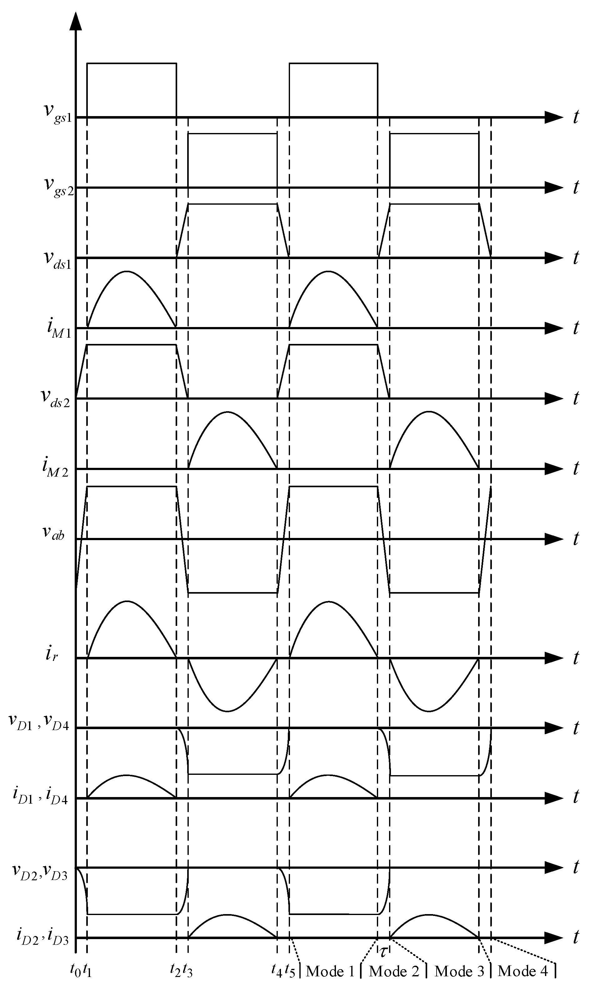
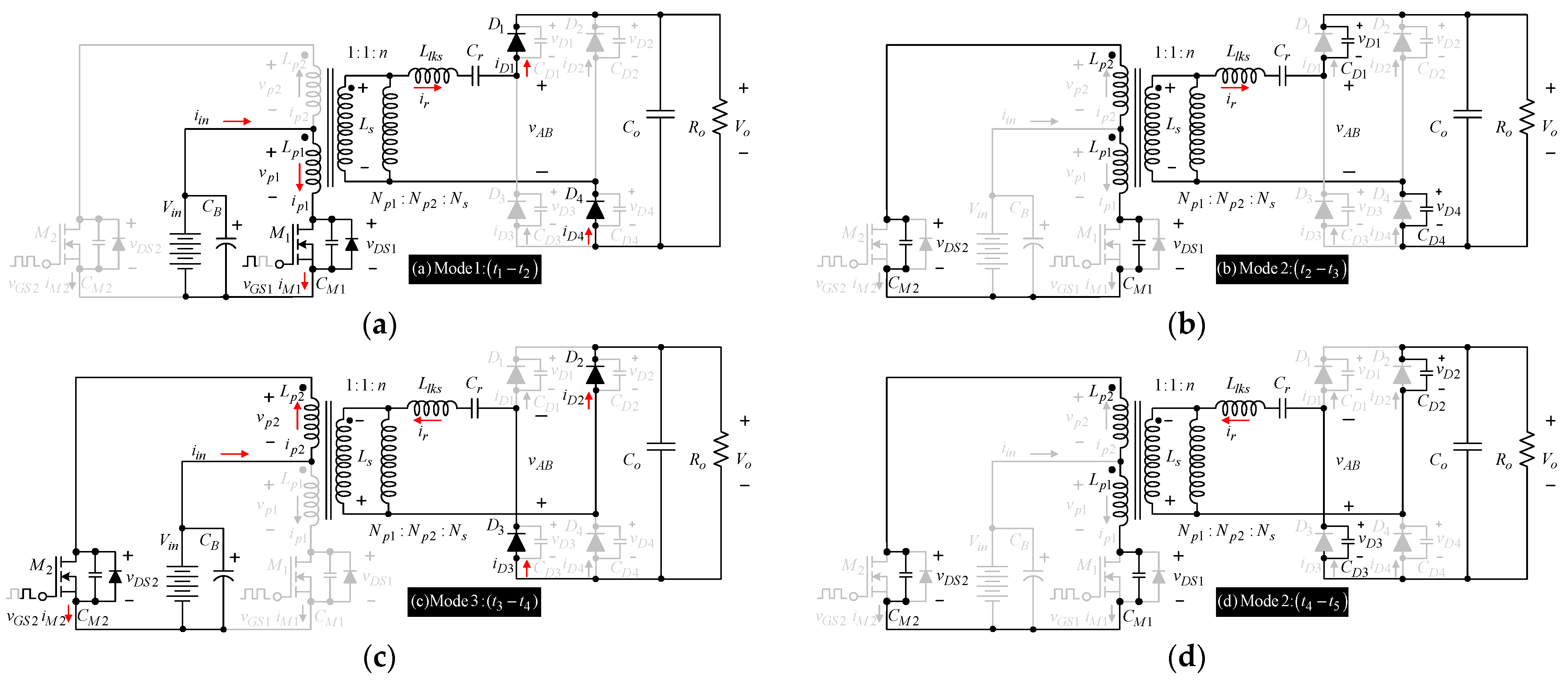
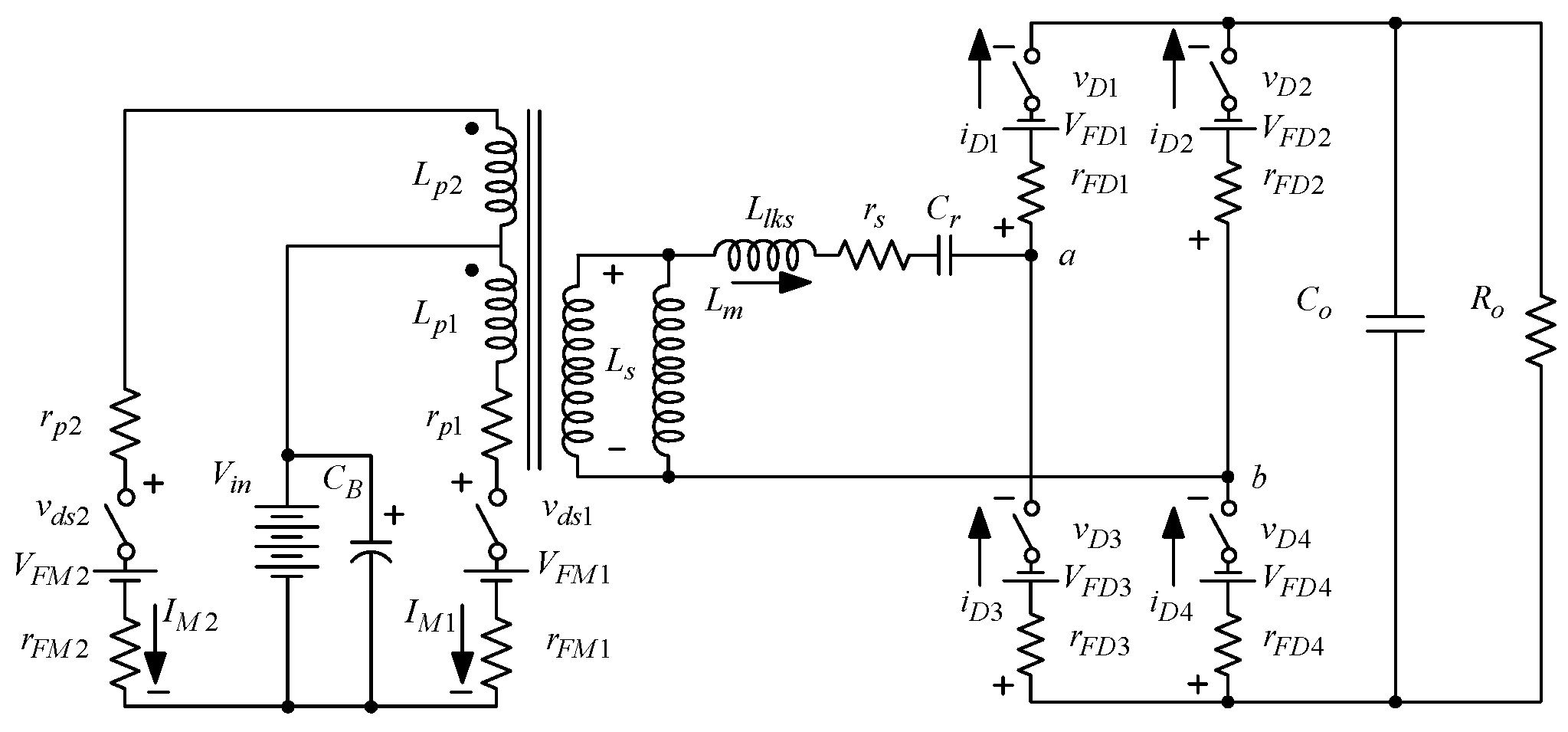
2. Circuit Description
3. Circuit Analysis
- The main power switch and active/passive elements in the on and off state are equal to zero and have infinite resistance.
- All passive components in the circuit are ideal and the initial condition is equal to zero.
- The load quality factor is higher so that the current is sinusoidal.
- The transformer is ideal and the value inductance of the primary side 1 is similar to the value of primary side 2.
- The output capacitor is sufficiently large for the output voltage to be constant.
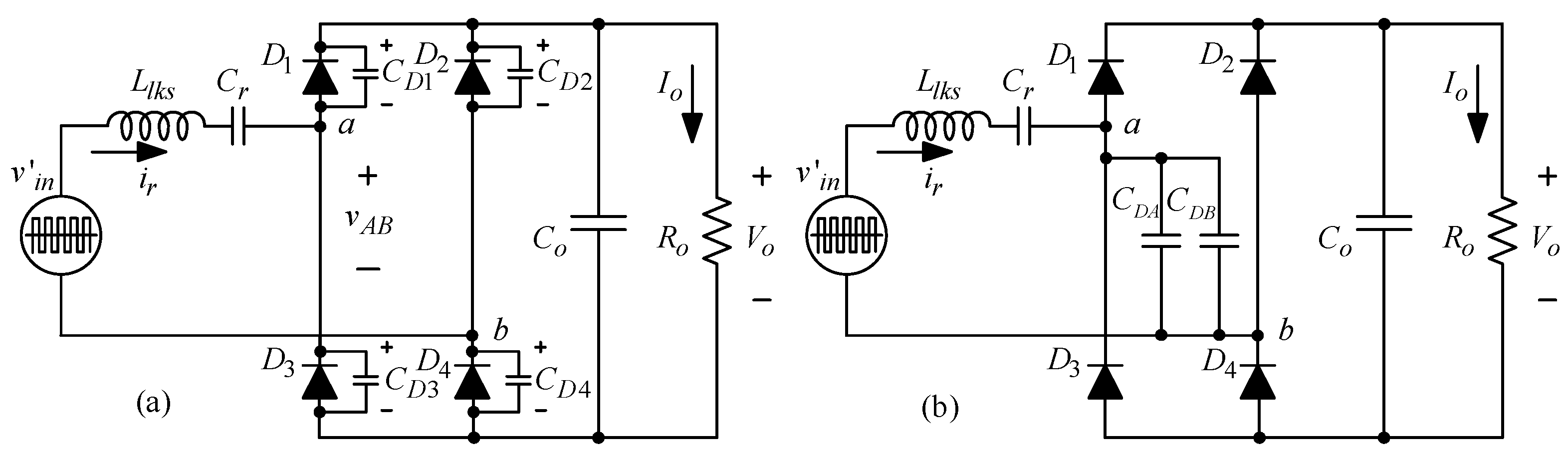
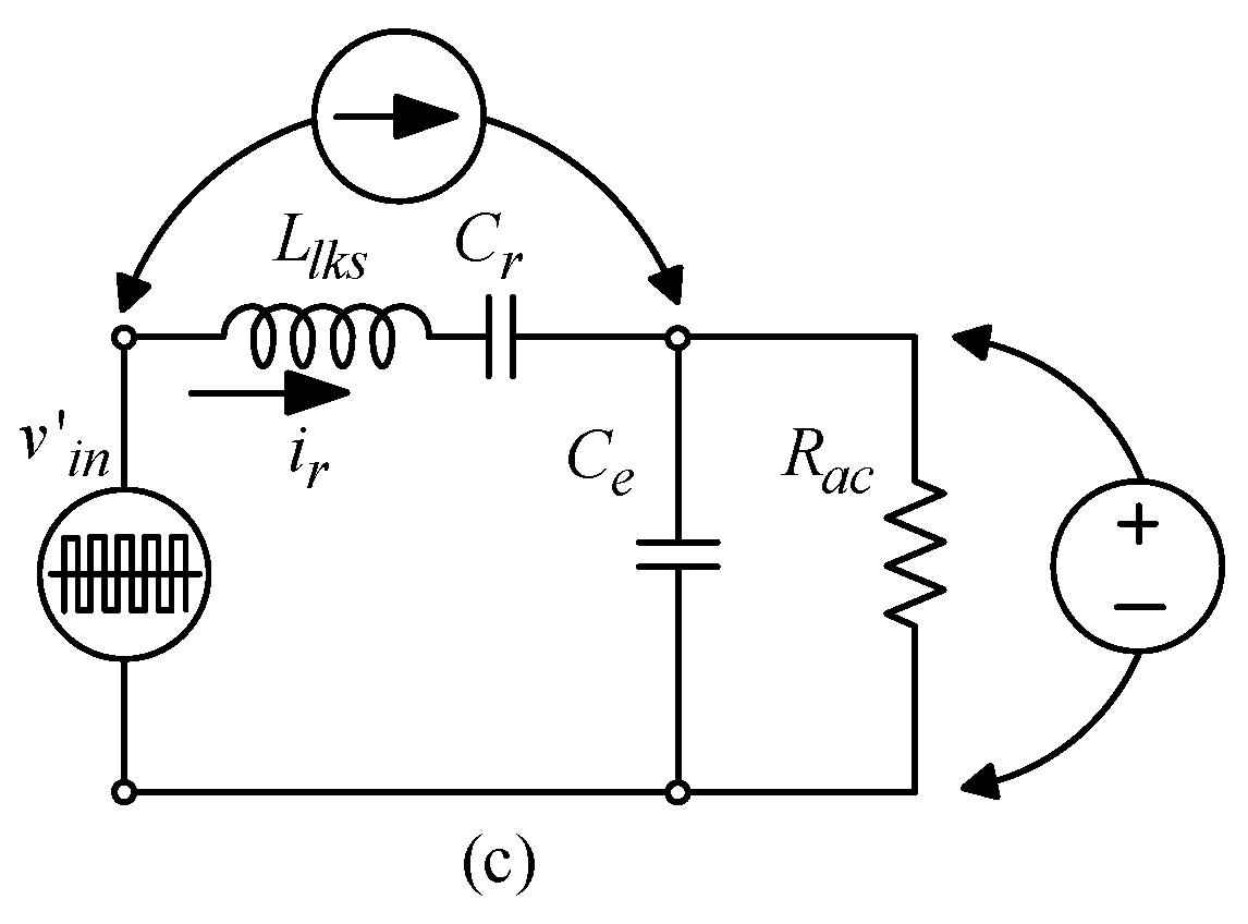
4. Analysis Modeling Resonant and Parasitic Capacitance Rectifier
5. Design Procedure
- Choose the voltage output Vo and the output power Po to determine the DC side-load resistance; it is then transferred to the resistance of the AC Rac side.
- Find the load quality factor QL value at full load, when the switching frequency fs is approximately equal to the resonant frequency.
- Find the junction capacitance Ce in the FBCSR from the characteristic diode.
- Find the equivalent resonant capacitance Cr.
- Find the value of the output capacitor Co and choose the ripple output to be less than 2%.
- Finally, calculate the conduction loss in the power switch Prds; the power loss in the diode rectifier PDB; the loss in transformer Prp, Prs; and the gate driving circuit loss Pgs.
5.1. High Step-up Push–Pull Multiresonant Converter
5.2. Analysis Conduction Power Loss and Efficiency
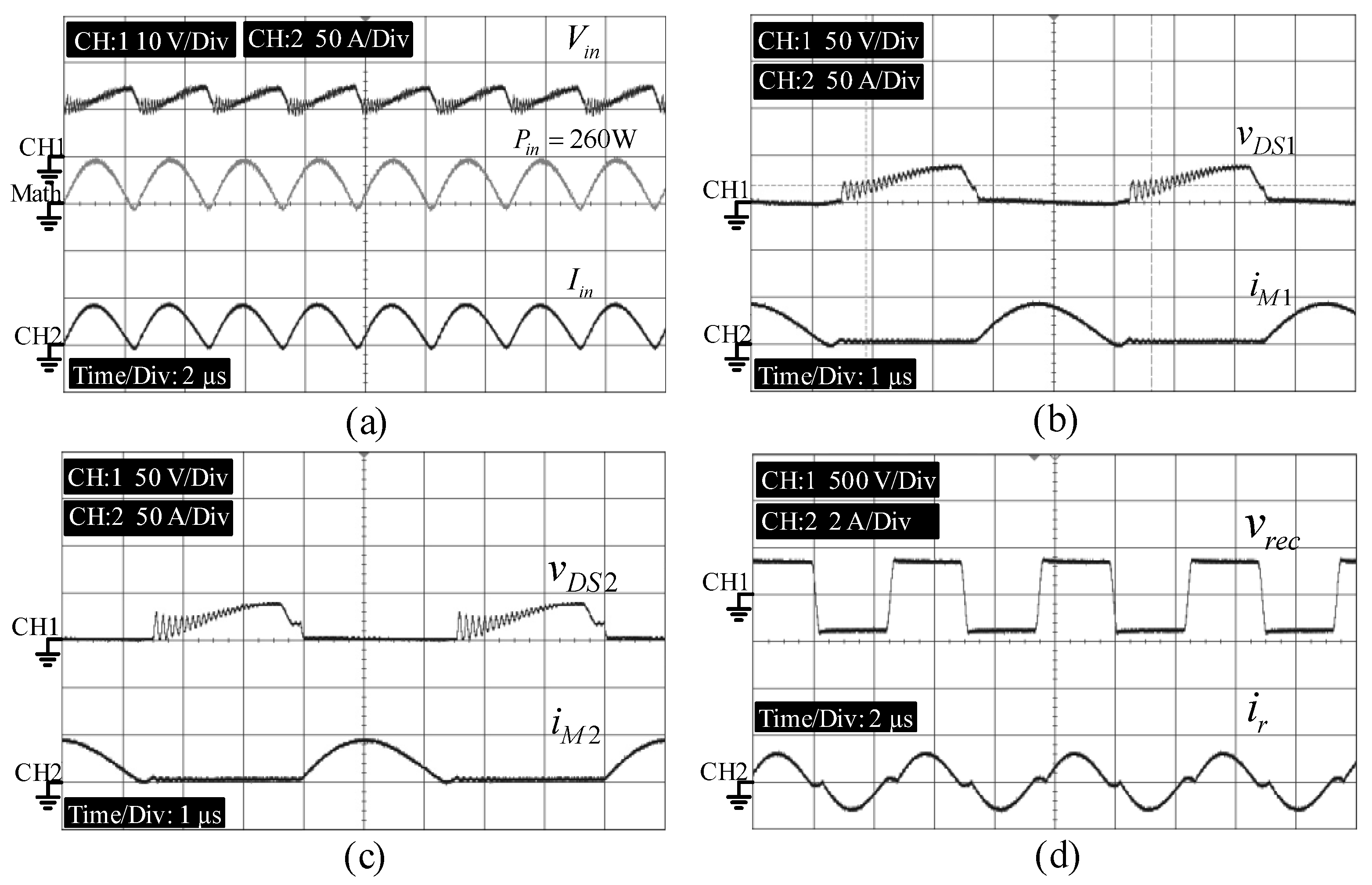
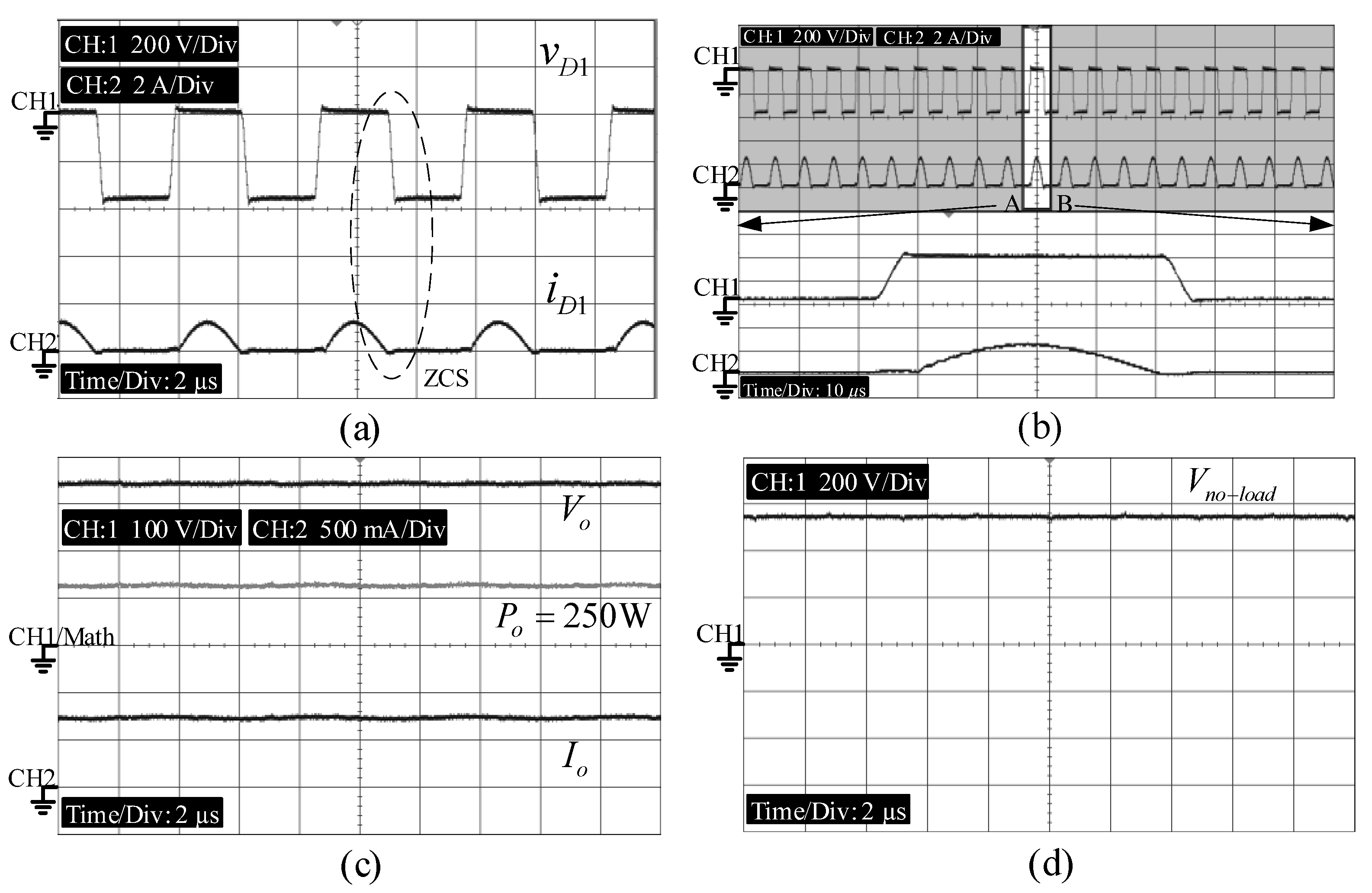
6. Experimental Results
7. Discussion of the Effected Parasitic Capacitance Diode of the FB-CDCSR and Experimental Results
8. Conclusions
- High voltage gain conversion ratio;
- Less components in the system;
- Leakage inductance and parasitic junction capacitance of the diode rectifier in the designed resonant tank, and simplified calculation;
- Additionally, the magnetic flux current in both main power switches can be easily balanced by a small leakage inductance at the input side.
Author Contributions
Funding
Institutional Review Board Statement
Informed Consent Statement
Data Availability Statement
Conflicts of Interest
References
- Li, Q.; Wolfs, P. A review of the single phase photovoltaic module integrated converter topologies with three different DC link configurations. IEEE Trans. Power Electron. 2008, 23, 1320–1333. [Google Scholar]
- Chen, Z.; Guerrero, J.M.; Blaabjerg, F. A review of the state of the art of power electronics for wind turbines. IEEE Trans. Power Electron. 2009, 24, 1859–1875. [Google Scholar] [CrossRef]
- Thounthong, P.; Davat, B.; Raël, S.; Sethakul, P. Fuel cell high power applications. IEEE Ind. Electron. Mag. 2009, 3, 32–46. [Google Scholar]
- Lin, B.R.; Dong, J.Y. New zero-voltage switching DC-DC converter for renewable energy conversion system. IET Power Electron. 2012, 5, 393–400. [Google Scholar] [CrossRef]
- Li, W.; He, X. Review of nonisolated high-step-up DC/DC converters in photovoltaic grid-connected applications. IEEE Trans. Ind. Electron. 2011, 58, 1239–1250. [Google Scholar] [CrossRef]
- Lee, Z.P.-W.; Lee, Y.-S.; Cheng, D.K.W.; Liu, X.-C. Steady-state analysis of an interleaved boost converter with coupled inductors. IEEE Trans. Ind. Electron. 2000, 47, 787–795. [Google Scholar] [CrossRef]
- Huang, X.; Wang, X.; Nergaard, T.; Lai, J.-S.; Xu, X.; Zhu, L. Parasitic ringing and design issues of digitally controlled high power interleaved boost converters. IEEE Trans. Power Electron. 2004, 19, 1341–1352. [Google Scholar] [CrossRef]
- Zhao, Q.; Lee, F.C. High-efficiency, high step-up dc–dc converters. IEEE Trans. Power Electron. 2003, 18, 65–73. [Google Scholar] [CrossRef] [Green Version]
- Inaba, C.Y.; Konishi, Y.; Nakaoka, M. High frequency PWM controlled step-up chopper type dc–dc power converters with reduced peak switch voltage stress. Proc. Inst. Elect. Eng. Elect. Power Appl. 2004, 151, 47–52. [Google Scholar] [CrossRef]
- Huber, L.; Jovanovic, M.M. A design approach for server power supplies for networking applications. In Proceedings of the 15th Annual IEEE Applied Power Electronics Conference and Exposition, New Orleans, LA, USA, 6–10 February 2000; Volume 2, pp. 1163–1169. [Google Scholar]
- Lin, B.-R.; Chen, J.-J. Analysis and implementation of a soft switching converter with high-voltage conversion ratio. IET Power Electron. 2008, 1, 386–394. [Google Scholar] [CrossRef]
- Shu, H.C. Design and analysis of a switched-capacitor-based step-up dc/dc converter with continuous input current. IEEE Trans. Circuits Syst. I Fundam. Theory Appl. 1999, 46, 722–730. [Google Scholar]
- Law, K.K.; Cheng, K.W.E.; Yeung, Y.P.B. Design and analysis of switched-capacitor-based step-Up resonant converters. IEEE Trans. Circuits Syst. I Reg. Pap. 2005, 52, 943–948. [Google Scholar] [CrossRef] [Green Version]
- Ismail, E.H.; Al-Saffar, M.A.; Sabzali, A.J.; Fardoun, A.A. A family of single-switch pwm converters with high step-up conversion ratio. IEEE Trans. Circuits Syst. I Reg. Pap. 2008, 55, 1159–1171. [Google Scholar] [CrossRef]
- Wai, R.J.; Duan, R.Y. High-efficiency power conversion for low power fuel cell generation system. IEEE Trans. Power Electron. 2005, 20, 847–856. [Google Scholar] [CrossRef]
- Peng, F.Z.; Zhang, F.; Qian, Z. A magnetic-less DC–DC converter for dual-voltage automotive systems. IEEE Trans. Ind. Applicat. 2004, 39, 1341–1352. [Google Scholar]
- Prudente, M.; Pfitscher, L.L.; Emmendoerfer, G.; Romaneli, E.F.; Gules, R. Voltage multiplier cells applied to non-isolated DC–DC converters. IEEE Trans. Power Electron. 2008, 23, 1320–1333. [Google Scholar] [CrossRef]
- Yao, Z.; Xiao, L. Family of zero-voltage-switching unregulated isolated step-up DC–DC converters. IET Power Electron. 2013, 6, 862–868. [Google Scholar] [CrossRef]
- Chu, G.M.L.; Lu, D.D.C.; Agelidis, V.G. Flyback-based high step-up converter with reduced power processing stages. IET Power Electron. 2012, 5, 349–357. [Google Scholar] [CrossRef]
- Spiazzi, G.; Mattavelli, P.; Costabeber, A. High step-up ratio flyback converter with active clamp and voltage multiplier. IEEE Trans. Power Electron. 2011, 26, 3205–3214. [Google Scholar] [CrossRef]
- Li, W.; Fan, L.; Zhao, Y.; He, X.; Xu, D.; Wu, B. High-step-up and high-efficiency fuel-cell power-generation system with active-clamp flyback–forward converter. IEEE Trans. Ind. Electron. 2012, 59, 599–619. [Google Scholar]
- Ryan, M.J.; Brumsickle, W.E.; Divan, D.M.; Lorenz, R.D. A new ZVS LCL -resonant push–pull DC–DC converter topology. IEEE Trans. Ind. Applicat. 1998, 34, 1164–1174. [Google Scholar] [CrossRef]
- Gopinath, R.; Kim, S.; Hahn, J.-H.; Enjeti, P.N.; Yeary, M.B.; Howze, J.W. Development of a low cost fuel cell inverter system with dsp control. IEEE Trans. Power Electron. 2004, 19, 1256–1262. [Google Scholar] [CrossRef]
- Thongsongyod, C.; Jirasereeamornkul, K.; Boonyaroonate, I.; Ekkaravarodome, C.; Higuchi, K. High step-up ratio DC-DC converter using class-E resonant inverter and class-DE rectifier for low voltage DC sources. In Proceedings of the International Conference on Electronics, Information, and Communication (ICEIC), Danang, Vietnam, 27–30 January 2016; pp. 1–4. [Google Scholar]
- Nagashima, T.; Wei, X.; Bou, E.; Alarcon, E.; Kazimierczuk, M.K.; Sekiya, H. Steady-state analysis of isolated class-E2 converter outside nominal operation. IEEE Trans. Ind. Electron. 2017, 64, 3237–3238. [Google Scholar] [CrossRef]
- Garcia, J.A.; Popovic, Z. Class-E rectifier and power converter. In Proceedings of the 2017 IEEE MTT-S International Microwave Symposium (IMS), Honololu, HI, USA, 4–9 June 2017; pp. 67–78. [Google Scholar]
- Meghdad, T.; Jafar, M.; Bijan, A. High step-up current-fed ZVS dual half-bridge DC–DC converter for high-voltage applications. IET Power Electron. 2015, 8, 309–318. [Google Scholar] [CrossRef]
- Park, C.; Choi, S. Quasi-resonant boost-half-bridge converter with reduced turn-off switching losses for 16 V fuel cell application. Lett. IEEE Trans. Power Electron. 2013, 28, 4892–4896. [Google Scholar] [CrossRef]
- Kwon, J.-M.; Kwon, B.-H. High step-up active-clamp converter with input-current doubler and output-voltage doubler for fuel cell power systems. IEEE Trans. Power Electron. 2009, 24, 108–115. [Google Scholar] [CrossRef]
- Kwon, J.-M.; Kim, E.-H.; Kwon, B.-H.; Nam, K.-H. High-efficiency fuel cell power conditioning system with input current ripple reduction. IEEE Trans. Ind. Electron. 2009, 56, 826–834. [Google Scholar] [CrossRef]
- Thippayanet, R.; Ekkaravarodome, C.; Jirasereeamornkul, K.; Chamnongthai, K.; Kazimierczuk, M.K.; Higuchi, K. Push-pull zero-voltage switching resonant DC-DC converter based on half bridge class-DE rectifier. In Proceedings of the IEEE 10th International Conference on Power Electronics and Drive Systems (PEDS), Kitakyushu, Japan, 22–25 April 2013; pp. 1162–1167. [Google Scholar]
- Chen, W.; Lu, Z.; Zhang, X.; Ye, S. A novel ZVS step-up push-pull type isolated LLC series resonant dc-dc converter for ups systems and its topology variations. In Proceedings of the 23rd Annual IEEE Applied Power Electronics Conference and Exposition, Austin, TX, USA, 24–28 February 2008; pp. 1073–1078. [Google Scholar]
- Boonyaroonate, I.; Mori, S. A new ZVCS resonant push-pull DC/DC converter topology. In Proceedings of the 17th Annual IEEE Applied Power Electronics Conference and Exposition, Dallas, TX, USA, 10–14 March 2002; Volume 2, pp. 1097–1100. [Google Scholar]
- Chu, C.-L.; Li, C.-H. Analysis and design of a current-fed zero-voltage-switching and zero-current-switching CL-resonant push—pull dc—dc converter. IET Power Electron. 2009, 2, 456–465. [Google Scholar] [CrossRef]
- Kim, E.-H.; Kwon, B.-H. High step-up resonant push—pull converter with high efficiency. IET Power Electron. 2009, 2, 79–89. [Google Scholar] [CrossRef]
- Lin, B.-R.; Dong, J.-Y.; Chen, J.-J. Analysis and implementation of a ZVS/ZCS DC–DC switching converter with voltage step-up. IEEE Trans. Ind. Electron. 2011, 58, 2962–2971. [Google Scholar] [CrossRef]
- Kosenko, R.; Chub, A.; Blinov, A. Full-soft-switching high step-up bidirectional isolated current-fed push-pull DC-DC converter for battery energy storage applications. In Proceedings of the 42nd Annual Conference of the IEEE Industrial Electronics Society, (IECON), Florence, Italy, 23–26 October 2016; pp. 6548–6553. [Google Scholar]
- Sree, K.R.; Rathore, A.K. Impulse commutated zero-current switching current-fed push-pull converter: Analysis, design, and experimental results. IEEE Trans. Ind. Electron. 2015, 62, 363–370. [Google Scholar] [CrossRef]
- Hagiwara, M.; Akagi, H. Experiment and simulation of a modular push–pull PWM converter for a battery energy storage system. IEEE Trans. Ind. Applicat. 2014, 50, 1131–1140. [Google Scholar] [CrossRef]
- Yuan, B.; Yang, X.; Li, D.; Pei, Y.; Duan, J.; Zhai, J. A current-fed multiresonant converter with low circulating energy and zero-current switching for high step-up power conversion. Lett. IEEE Trans. Power Electron. 2011, 26, 1613–1619. [Google Scholar] [CrossRef]
- Li, D.; Liu, B.; Yuan, B.; Yang, X.; Duan, J.; Zhai, J. A high step-up current fed multi-resonant converter with output voltage doubler. In Proceedings of the 26th Annual IEEE Applied Power Electronics Conference and Exposition, Fort Worth, TX, USA, 6–11 March 2011; pp. 2020–2026. [Google Scholar]
- Yuan, B.; Yang, X.; Zeng, X.; Duan, J.; Zhai, J.; Li, D. Analysis and design of a high step-up current-fed multi resonant DC–DC converter with low circulating energy and zero-current switching for all active switches. IEEE Trans. Ind. Electron. 2012, 59, 964–978. [Google Scholar] [CrossRef]
- Kim, Y.-H.; Shin, S.-C.; Lee, J.-H.; Jung, Y.-C.; Won, C.-Y. Soft-switching current-fed push–pull converter for 250-W AC module applications. IEEE Trans. Power Electron. 2014, 29, 863–872. [Google Scholar]
- Wu, Z.Q.; Wang, Q.; Xu, J.; Li, H.; Xiao, L. A high-efficiency step-up current-fed push-pull quasi-resonant converter with fewer components for fuel cell application. IEEE Trans. Ind. Electron. 2017, 64, 6639–6648. [Google Scholar] [CrossRef]
- Ang, Y.; Foster, M.P.; Sewell, H.I.; Du, C.M.Y.; Stone, D.A. Stress analysis of fourth-order LLCC resonant converters. Electron. Lett. 2002, 38, 1585–1586. [Google Scholar] [CrossRef]
- Du, Y.; Wang, G.; Wang, J.; Bhattacharya, S.; Huang, A.Q. Modeling of the impact of diode junction capacitance on high voltage high frequency rectifiers based on 10kV SiC JBS diodes. In Proceedings of the IEEE Energy Conversion Congress and Exposition, Atlanta, GA, USA, 12–16 September 2010; pp. 105–111. [Google Scholar]
- Du, Y.; Wang, J.; Wang, G.; Huang, A.Q. Modeling of the high-frequency rectifier with 10-kV SiC JBS diodes in high-voltage series resonant type DC–DC converters. IEEE Trans. Power Electron. 2014, 29, 4288–4300. [Google Scholar] [CrossRef]


| Parameter | Symbol | Value/Part Number | Type |
|---|---|---|---|
| Input voltage | Vin | 12 VDC | - |
| Output voltage | Vo | 340 VDC | - |
| Output power | Po | 250 W | - |
| Output capacitor | Co | 0.33 µF | Polypropylene |
| Switching frequency | fs | 200 kHz | SG3525 Gate Driver |
| Power MOSFETs | M1, M2 | IRFP 3205 | N-Chanel MOSFETs |
| Fast recovery diode | D1–D4 | MUR 860 | Fast-Recovery Diode |
| Resonant capacitance | Cr | 1.8 nF | Polypropylene |
| Resonant inductance | Lr | 389.8 µH | EE42/13/7 N87-EPCOS |
| Inductance primary | Lp1, Lp2 | 12.07 µH, 12.02 µH | EE42/13/7 N87-EPCOS |
| Inductance secondary | Ls | 14.50 mH | EE42/13/7 N87-EPCOS |
| Leakage inductance primary | Llk1, Llk2 | 0.41 µH, 0.43 µH | EE42/13/7 N87-EPCOS |
| Parasitic junction capacitor diode | CD1-CD4 | 75 pF | - |
| Parameter | Ref [4] | Ref [8] | Ref [17] | Ref [19] | Ref [20] | Proposed Circuit |
|---|---|---|---|---|---|---|
| Range input voltage | 48 VDC | 60 VDC | 24 VDC | 24 VDC | 35 VDC | 12 VDC |
| Range output voltage | 400 VDC | 380 VDC | 400 VDC | 200 VDC | 400 VDC | 340 VDC |
| Switching frequency | 120 kHz | 120 kHz | 40 kHz | 100 kHz | 100 kHz | 200 kHz |
| Range output power | 400 W | 1 kW | 400 W | 60 W | 300 W | 250 W |
| Range efficiency | ≥90% | ≥90% | ≥90% | ≥90% | ≥90% | ≥90% |
| Conversion ratio | 8.33 | 6.33 | 16.66 | 8.33 | 11.42 | 28.3 |
| Topology circuit | series 2 boost converters | buck–boost clamp mode | boost voltage multiplier cells | Modify-flyback volt double | Flyback-active clamp voltage multiplier | push–pull traditional |
| Voltage across switches | normal | normal | normal | high | normal | normal |
| Number of switches | 1 main 1 auxiliary | 1 main | 1 main | 1 main | 1 main 1 active clamp | 2 mains |
| Number of capacitors | 5 | 1 | 3 | 2 | 4 | 1 |
| Number of inductors | 1 transformer (2 inductors) nonisolated | 1 transformer (2 inductors) nonisolated | 2 inductors nonisolated | 1 transformer (2 inductors) nonisolated | 1 transformer (2 inductors) isolated | 1 transformer (2 inductors) isolated |
| Number of diodes | 3 | 2 | 3 | 2 | 2 | 4 |
| Component count | 11 | 5 | 9 | 6 | 9 | 8 + 2 (Cin and Cr) |
| Parameter | Ref [27] | Ref [35] | Ref [36] | Ref [38] | Ref [42] | Ref [44] | Proposed Circuit |
|---|---|---|---|---|---|---|---|
| Range input voltage | 50 VDC | 30–70 VDC | 48 VDC | 38–50 VDC | 23–38 VDC | 30–50 VDC | 12 VDC |
| Range output voltage | 400 VDC | 350 VDC | 400 VDC | 380 VDC | 350 VDC | 350 VDC | 340 VDC |
| Switching frequency | 50 kHz | 70 kHz | 74 kHz | 200 kHz | 255 kHz | 100 kHz | 200 kHz |
| Range output power | 250 W | 1.5 kW | 400 W | 500 W | 150 W | 510 W | 250 W |
| Range efficiency | ≥90% | ≥90% | ≥90% | ≥85% | ≥90% | ≥90% | ≥90% |
| Conversion ratio | 8/1 | 11.6/5/1 | 8.3/1 | 10/8.6/7.6/1 | 15.2/9.2/1 | 11.6/7/1 | 28.3/1 |
| Operation mode main state | ZVS | ZVS | ZVS | ZCS | ZCS | ZVS | ZCS |
| Topology rectifier | volt double 2 modules | volt double 1 module | center tap II 1 module | bridge 1 module | volt double 1 module | volt double 1 module | bridge 1 module |
| Stress voltage/mode | 2 Vo/ZCS | 2 Vo/ZCS | 2 Vo/ZCS | Vo/ZCS | 2 Vo/ZCS | 2 Vo/ZCS | Vo/ZCS |
| Balance flux transformer | N/A | unbalance | unbalance | balance | unbalance | unbalance asymmetrical | balance |
| Useful parasitic capacitance | neglect | neglect | neglect | adoption | neglect | neglect | utilization |
| Classify resonant | LC series resonant | LC series resonant | LC series resonant | LC parallel resonant | LC parallel resonant | LC parallel resonant | LC series multiresonant |
| Number of inductors or transformer/capacitors | 2 transformers 3 capacitors | 1 transformer 1 inductor 3 capacitors | 1 transformer 1 inductor 1 capacitor | 1 transformer 1 inductor | 1 transformer 2 inductors 1 capacitor | 1 transformer 1 inductor 1 capacitor | 1 transformer 1 capacitor |
| Number of main switches | 2 switches | 2 switches 2 actives | 2 switches | 2 switches | 2 switches | 2 switches 1 active | 2 switches |
| Number of rectifiers side | 4 diodes 3 capacitors | 2 diodes 3 capacitors | 2 diodes 3 capacitors | 4 diodes 2 capacitors | 2 diodes 3 capacitors | 2 diodes 3 capacitors | 4 diodes 2 capacitors |
| Component count | 14 | 13 | 10 | 10 | 11 | 11 | 10 |
Publisher’s Note: MDPI stays neutral with regard to jurisdictional claims in published maps and institutional affiliations. |
© 2021 by the authors. Licensee MDPI, Basel, Switzerland. This article is an open access article distributed under the terms and conditions of the Creative Commons Attribution (CC BY) license (https://creativecommons.org/licenses/by/4.0/).
Share and Cite
Bilsalam, A.; Ekkaravarodome, C.; Chunkag, V.; Thounthong, P. Analyzing the Effect of Parasitic Capacitance in a Full-Bridge Class-D Current Source Rectifier on a High Step-Up Push–Pull Multiresonant Converter. Sustainability 2021, 13, 5477. https://doi.org/10.3390/su13105477
Bilsalam A, Ekkaravarodome C, Chunkag V, Thounthong P. Analyzing the Effect of Parasitic Capacitance in a Full-Bridge Class-D Current Source Rectifier on a High Step-Up Push–Pull Multiresonant Converter. Sustainability. 2021; 13(10):5477. https://doi.org/10.3390/su13105477
Chicago/Turabian StyleBilsalam, Anusak, Chainarin Ekkaravarodome, Viboon Chunkag, and Phatiphat Thounthong. 2021. "Analyzing the Effect of Parasitic Capacitance in a Full-Bridge Class-D Current Source Rectifier on a High Step-Up Push–Pull Multiresonant Converter" Sustainability 13, no. 10: 5477. https://doi.org/10.3390/su13105477
APA StyleBilsalam, A., Ekkaravarodome, C., Chunkag, V., & Thounthong, P. (2021). Analyzing the Effect of Parasitic Capacitance in a Full-Bridge Class-D Current Source Rectifier on a High Step-Up Push–Pull Multiresonant Converter. Sustainability, 13(10), 5477. https://doi.org/10.3390/su13105477