
A Trans-Disciplinary Vocabulary for Assessing the Visual Performance of BIPV

(TERIN-FSD-DIN) Research Centre Portici, Innovative Devices Laboratory, Renewable Energy Technologies Department, Photovoltaics and Smart Devices Division, Italian National Agency for New Technologies, Energy and Sustainable Economic Development, ENEA, 80055 Portici, Italy
Sustainability 2021, 13(10), 5500; https://doi.org/10.3390/su13105500
Submission received: 24 March 2021
/
Revised: 28 April 2021
/
Accepted: 7 May 2021
/
Published: 14 May 2021
(This article belongs to the Special Issue Energy Transition and Cities: Renewable Energy Storage, Production and Social Issues)
Abstract
:It is widely acknowledged that the visual dimension of photovoltaics (PV) is fundamental for social acceptance. In this sense, the so-called Building Integrated Photovoltaics (BIPV) is a possible catalyzer, as PV is hidden (integrated) into building envelope morphologies that are familiar to the public. It is crucial to be able to design and assess a BIPV system so that its visual performance is optimal. Many studies exist in this regard, but still they do not deliver a clear theoretical organization of the concepts used for defining the visual performance of BIPV. This paper elaborates a trans-disciplinary systemic formalization of BIPV and proposes a vocabulary focusing on the formal perception of BIPV as a part of the building’s envelope system. The proposed vocabulary is based on a set of 11 visual keywords; as the proposed method unifies the formal and the cognitive information contents. It will facilitate the dialogue among different stakeholders (e.g., architects, clients, modules manufacturers, and public authorities) and, in general, the visual performance assessment of BIPV. In consequence, it allows for objective comparison and thus informed decision-making.
1. Introduction
It is widely acknowledged that the visual dimension of photovoltaics (PV) is fundamental for social acceptance. In this sense the so-called Building Integrated Photovoltaics (BIPV) is a possible catalyzer when PV is hidden (integrated) into building envelope morphologies that are familiar to the public. This makes PV more acceptable, as aesthetic preferences are affected by familiarity [1], and the variety of design options help to achieve a satisfying visual performance for BIPV.
If perception is a crucial part of the social acceptance, as it allows people to criticize, interpret, differentiate, and analyze their surrounding environment based on their intrinsic values, in order to adapt to the environment [2], then visual perception is the key driver, as vision accounts for about 80% of the human perception [3]. Not surprisingly, a lot of research has been conducted since the 1990s on the visual aspects of PV, i.e., identifying sets of parameters that can be useful in defining some clear principles to guide the design of a “beautiful” BIPV system, or to set up appropriate criteria for the assessment of BIPV ex post.
In general, there is a common approach in separating “objective” and “subjective” aspects of the perception, with a focus on the objective ones, trying to limit the complexity of the aesthetic perception, with the aim of developing simple design and assessment tools.
With reference to the aesthetic impact assessment, a difference has been made between the “objective aesthetic impact” and on “subjective judgement”, and variables of aesthetic impact have been identified for solar power plants in elements such as visibility, color, fractality, and concurrence [4].
An alternative and complementary method for evaluating the BIPV visual impact using the saliency method with an objective, quantitative, and neuropsychological-based approach has been developed, too [5].
Visual Q methodologies have also been adapted for assessing the impact of PV applications on the landscape in urban areas [6].
Visual impact indicators have been described as simple and complex. The first category includes factors such as color, glare, pattern–texture, and fractality; the second includes visibility and integration degree [7].
For mastering the visual impact of solar systems in urban environments, the “LESO-QSV method” uses complex factors, such as quality, sensitivity, and visibility [8]. Similar approaches can be found also in other works of the literature attributable to the international collaborative research work of the IEA-SHC Task 41, on criteria for the architectural integration of active solar systems [9].
Nevertheless, the cognitive frameworks based on subjective and objective categories of perception demonstrate themselves to be somehow only approximate and ineffective.
Firstly, “Perception is a relationship, and it is therefore subjective and objective at the same time. Sensorial stimuli are born from physical facts (…) but the red, the savoury, or the hot are not in nature. They are parts of reality that our senses promote to the rank of sensation. Perception is a construction of the brain, guided by continuous feedbacks from the environment, which reassure us on the stability of thing” [10].
Secondly, in the aesthetic experience, the cognitive domain has a central role, and, once again, any room for anything “objective” is limited. Aesthetic information processing is a multi-stage process, with an initial stage that corresponds to the perceptual and cognitive appraisal of the object’s basic properties and the like: a further main stage based on the detection of more complex compositional regularities and the interpretation of more sophisticated narratives and hidden symbolism of the object’s structure; and a final stage accompanied by a feeling of an exceptional and unique relationship with the object of fascination (object, cognition, attention, and emotion) [11]. The nature of aesthetic response can be described as a process through sensory (initial impact of the senses), formal (compositional factors and understanding of patterns), expressive (pre- or post-perceptual knowledge and sensory information enter a critical discussion to come to terms with what is perceived), and symbolic (received cultural context and culturally conditioned meaning) [3].
Concepts used in the existing literature reflect the difficulty in building up a correct, systemic descriptive framework for assessing the visual performance of BIPV. Different aspects of the perception, and stages of the aesthetic experience and response are mixed up, without a clear theoretical organization.
For example, the abovementioned LESO–QSV method proposes that, for being architecturally integrated and perceived as such, a BIPV system has to be designed so that “all the formal (i.e., visual) characteristics of the solar energy system, have to be coherent with the global building design logic” [8], and mentions concepts such as the following: collectors field size and position, visible materials, surface textures, colors, modules shape/size, and jointing system. This description mixes up perceptual and knowledge aspects, as well as different stages of the visual perception and of the aesthetic response, as reflected by the vocabulary. The aim is defining the domain of the formal composition, and nevertheless the vocabulary is “spurious”, as it mixes visual concepts with architectural and/or technological concepts that are not part of the visual information, but do rather relate to a possible cognitive aesthetic response.
To build up an appropriate cognitive framework for describing BIPV as a visual object, there is a need for a visual vocabulary of BIPV for the form and composition of BIPV. Moreover, to enable a cognitive framework one needs to include also architectural and technological knowledge (quantitative and technical information), as shown in Figure 1.
This study is a contribution to the architectural design and the visual performance assessment of BIPV, by providing a trans-disciplinary perspective. It elaborates a visual vocabulary and associated semiology of BIPV, focusing on the formal perception of BIPV, which includes concepts and definitions already used in the BIPV field, and some others originating from visual disciplines. Moreover, in order to give a systematic organization to visual and functional patterns, it advances a new cognitive framework. The background for framework of the study is the IEA PVPS Task 15.2. Subtask B: Cross-Sectional Analysis. The main purpose of this subtask is the development of a multidimensional evaluation matrix to determine the (a) energy-relevant, (b) economic, (c) visual, and (d) environmental performance of BIPV. To do so, for each of the dimensions, performance parameters have to be defined.
2. Methodological Approach
How to build up the cognitive framework for understanding a BIPV system as a visual object?
As it has been noted, “Intuitively, objects are components of the subjective visual interpretation that are both coherent and complete. Hence defining them formally means asking how subjective interpretations are formally structured, and then considering how this kind of formal structure most naturally decomposes, or ‘breaks apart at the seams’. A very natural way of expressing perceptual interpretations is in terms of hierarchical descriptions, i.e., trees. (…) Formally, a hierarchical description corresponds to a tree, in which the root node (normally drawn at the top) describes the configuration at the most global level, while its subtrees describe finer or more local spatial relations, and their subtrees even finer ones, all the way down to the leaves, which correspond to individual visual elements (pixels, dots, oriented edges, etc.)” [12].
In support of this approach, it can be remarked that “The visualization of any object, takes place only by the medium of figural elements that are simple in their structure, such as square, circle, triangle, etc., that are the so called ‘representative objects’ or historical forms of knowledge (Argan)” [13]. Moreover, “Whatever our views, our cultural background or the values we attach to certain landscapes, we perceive them, at the most basic, structural level as patterns” [3].
Coherently with this background, what is achieved in this work is the following (see Figure 2):
- Identification of the individual visual elements (the “leaves”);
- Formalization of a hierarchical configuration of the individual visual elements (leaves) into subtrees and trees, to the highest level of a tree, the root node.
Structuring the tree needs the technical knowledge of the functional features of a BIPV system and, also, the ability of describing all its technological options as visual elements through appropriate concepts and vocabularies at the appropriate scales. As it is better elaborated in the next paragraphs, considering the specificity of a BIPV system, three scales (branches of the tree) are considered:
- The building mosaic pattern, which includes the BIPV system as a tile of the mosaic;
- The BIPV system, which includes the BIPV components;
- The BIPV components, which include PV units and materials.
A rich collection of works in the literature exists that helps in describing a BIPV system in its architectural, engineering, and technological aspects, whereas a new perspective should be elaborated for describing it as a visual object. The concept of “pattern”, which is a medium between different disciplines, is used here as a starting point.
Taking from the foundations of the landscape ecology, concepts such the patch–corridor–matrix model, and the relative vocabulary for their structural attributes (pattern and texture), are further elaborated for a better coherence with the object of investigation. A cognitive advancement is conducted by adopting key concepts—namely the descriptive principles—from the Gestalttheorie [14,15,16].
3. Theoretical Framework: The BIPV System as a Polysemous Sign
The disciplinary knowledge of BIPV is very variegated, and none of the single disciplinary approaches is able to entail the whole complexity of BIPV, conceived as a part of the building’s envelope, as a visual system, and as a complex choice of technological options suited for desired quality objectives.
It is necessary to organize the different disciplinary knowledge in a way that enables to structuring a systemic organization, which allows to unify multiple, divided disciplinary perspectives.
A truly trans-disciplinary methodological approach (knowledge organization) is needed, as it enables us to overcome disciplinary knowledge that is fragmentary and divided and to set up a new appropriate perspective that connects and separates in a circular process [17]. To do this, a new “eye” is needed. This includes to consolidate the perspectives of BIPV with reference to the building envelope technologies and the PV technologies (PV devices) in a systemic cross-scale visual description.
After all, we perceive visually, and we design technically, and what we see is the result of a design; this is the reason why it is impossible to separate the visual from the technological aspects, or, in other words, design cannot be disconnected from the visual performance.
An appropriate semiology, together with and appropriate vocabulary for BIPV is needed due to the multiple faceted features of a BIPV system. To do so, the BIPV system is considered as a sign.
Semiology as codified by de Saussure teaches that a linguistic sign has a significant (significant—the form) and a meaning (signifié—the concept) and that they are inseparable; it is defined as «entité psychique à deux faces» that «unit non une chose et un nom, mais un concept et une image acoustique» [18].
The case of BIPV is complex, because a BIPV system or component, is for its nature multi-functional, and it is therefore the integration of different functional and visual concepts, that are represented by a unique sign, being a polysemous sign. In the following, different concepts and vocabularies for BIPV are proposed.
3.1. BIPV as a Photovoltaic System
In general, a PV system is a modular system, whose basic elements, the modules, are arranged in a way to ensure its optimal performance. The modules can use different PV technologies, such as thin film or crystalline silicon, and can have different back or front materials. Thin films are associated to dark uniform surfaces of the modules, whereas crystalline silicon technologies imply the use of PV cells (generally square and ranging from 10 to 15 cm in side length) arranged in the module configuration (pattern). “Standard” modules can be considered as multilayer components, in which simple configurations with the minimum number of layers are used (back layer, encapsulant, PV layer, encapsulant, and front layer). In the case of ground mounted PV, generally the modules are mounted in arrays that are E–W oriented so that the modules surface is able to capture the maximum amount of solar radiation along the day (azimuth 0°, south, in the northern hemisphere; azimuth 180°, north, in the southern hemisphere). Depending on the latitude, the modules are inclined relative to the horizontal ground (tilt) so as to maximize the solar yield along the year but also to allow for self-cleaning by the surface flow of rain water.
In the case of BIPV, the system is a part of the building’s envelope, performing all the functions typical of the traditional building envelope subsystem it replaces. In this case the spatial arrangement of the modules supports an optimal integration into the building envelope—rather than the optimal yearly normalized energy production; therefore, there is a variety of possibilities in terms of topology (in the building envelope: facade, roof, and external integrated device), morphology (envelope technology sub-system: rain screen facade, double-skin facade, curtain wall, window, masonry wall, discontinuous roofing, continuous roofing, atrium/skylight, parapet, balustrade, canopy, and solar shading), and orientation (azimuth and tilt angles). In Figure 3, an example of a BIPV system, where standard PV modules are added on the façade, is shown.
The BIPV modules have specific performance requirements because they are properly conceived for being integrate into the envelope. For this reason, there are a number of design parameters that can be considered. For instance, in the case of the so called “PV glasses” (photovoltaic modules that use glass both as front and back layers) the arrangement of the cells into the module can be performed so that a certain degree of transparency is achieved for allowing daylight transmission in the building (Figure 4).
As it is better described further in the study, PV glasses offer wide design options, thanks to the possibility of varying the layering of the module towards configurations that allow desired visual performances.
3.2. BIPV as a Part of the Building Envelope
The design possibilities of a BIPV have been deeply investigated in the past 20 years, following the technology development of PV, and the new market demands. Several studies have shown the technological and design options of PV at different scales [19,20,21,22,23,24,25]; the use of PV in buildings and the choice of the appropriate PV components [26]; and recently, a review exhaustively approached the technological design options for BIPV [27]. For further knowledge, refer to the specific works in the literature, as this is not the focus of this study.
Here, regarding the integration of PV in the building’s envelope, it is sufficient to say that a BIPV system can be integrated in the facade; in the roof; or in an external integrated device. Then, some other distinctions can be made.
- For the facade: rainscreen facade, double-skin facade, curtain wall, window, and masonry wall.
- For the roof: discontinuous roofing, continuous roofing, and atrium/skylight.
- For the external integrated device: parapet, balustrade, canopy, and solar shading [28].
3.3. BIPV as a Visual Image
In this paragraph, by analyzing the BIPV system as a visual sign, the main research question is: How many invariants are needed to make an image recognizable as a BIPV system? How far the variants have to go to make the BIPV system not recognizable as such? What are the most meaningful parts of the visual image of BIPV that make PV distinguishable as such?
In this context, the BIPV system cannot be seen other than a hierarchal organization of visual elements. In fact, a definition of “visual object” reads as follows: “visual objects cannot be defined according to simple physical properties but can instead be understood in terms of the hierarchical organization of visual scene interpretations. Within the tree describing such a hierarchical description, certain nodes make natural candidates as the ‘joints’ between objects, representing division points between parts of the image that cohere internally but do not perceptually group with one another. Thus, each subtree hanging from such a node corresponds to a single perceived ‘object’. This formal definition accords with several intuitions about the way objects behave” [12].
3.3.1. Variants of BIPV (Customization Degree)
What are the possible variants of BIPV? The number of the design possibilities offered by the PV technology vary depending on the degree of customization of the product.
In this sense there are many variants offered by an appropriate use of the layers in the design of a PV module (i.e., color, texture, and transparency). Among these are a variety of design options for the technological sub-components’ front and rear cover materials, front or rear encapsulant, and PV cell layers, and each of these opens a set of design possibilities and consequent visual options [27,29].
In the following, a red line is followed, from the lowest to the highest degree of customization.
The main design parameters of the module vary depending on whether crystalline silicon or thin film technology is used. In the case of crystalline silicon, the main design parameters are the pattern of the PV cells in the module [30], the electrical contacts design, and the addition of a “decorative” layer in the layering of the module, as this can vary the typical appearance of PV in the case of glass–glass components [31]. Thin-film technologies theoretically can offer flexibility in the surface visual appearance, but they are limited by cost constraints linked to the production volume [23].
The surface effect of the module (mat or glossy) depends on the grain of the materials used for the front layer of the module. Namely, the attitude of the surface of the module to reflect light depends on the smoothness of the surface of the external layer of the module, that is itself depending on the grain of the material (this is generally the external glass of the modules).
With the decrease of costs of PV, and therefore a decreased attention on the energy efficiency of the modules, new design possibilities have emerged, mainly ascribable to the possibility of using textures for the front side of the module, that decrease somehow the efficiency but increase the visual performance of the components.
In this sense there are many potentialities an appropriate use of the layers offers in the design of a certain visual appearance of a BIPV module. As shown in specific works in the literature, among these are the variety of design options for the technological sub-components’ front and rear cover materials, front or rear encapsulant, and PV cell layer, and each of them opens a set of design possibilities and consequent visual options.
As examples of different designs of the BIPV module, based on the variants mentioned so far, a few examples are given in the following.
Boogie-Woogie is a glass–glass module with a random cells pattern and the use of an additional ink jet printing PVB layer for enhancing the appearance of the BIPV from inside the building, and hiding the electrical connections, patented by ENEA in 2005 [32].
Within the European project Construct PV [33,34], financed from the 7th Framework Programme of the European Commission [33,34], a module with improved appearance through the application of a gloss/frit (front layer) and the use of a textured back layer [35] was registered as a design patent [36].
The association Compáz (member of Be-Smart Project and of Hiperion Project, funded by the European Union’s Horizon 2020 Research and Innovation Programme) developed modules that show high-definition images instead of the organic texture of PV developed by using technology developed at CSEM that allows for high definition images as texture of modules [37]. CSEM developed white and colored modules through selective scattering filters, which scatter the whole visible spectrum while transmitting infrared light [38]. The Lucerne University of Applied Sciences and Arts developed colored and textured modules, by printing patterns on the glass surface of the modules, using a digital ceramic printing process [39].
A number of these innovative modules are now available on the market, being part of several companies offer for projects that require a high degree of customization.
3.3.2. The Need for a Visual Vocabulary for BIPV
The vocabularies for the description used in the previous sections, Section 3.1 and Section 3.2, work very well if the part of the building that is the object of the description is recognizable as PV (Figure 3 and Figure 4), and if the meanings of the words used are meaningful to anyone. That is saying that they work well when the visual variants of BIPV are limited.
What happens if the observer can grasp nothing that can match the mainstream cognition of PV? The examples in Figure 5, Figure 6 and Figure 7 are very evident examples of cases that challenge the perception, even when the observer does have knowledge of PV.
In all of these cases, the external surface of the module looks different than the standard one, as additional layers have been added on the external side of the module, or special treatments have been made on the glass surface, for achieving desired visual effects, namely BIPV to be invisible. This is the reason why the description has to use a visual vocabulary.
3.3.3. Recognizability (Invariants of BIPV)
So, there are extreme cases where PV is invisible—thanks to the use of customized PV modules—and other cases where the use of PV is emphasized—through the use of standard PV modules. What happens in between the highest recognizability of PV and the lowest?
The scope of this paragraph is investigating what is (or if there is) the minimum set of spatial and visual elements that the observer needs for recognizing a BIPV system, and what are the most powerful discriminating visual elements. Sometimes the variation of the visual image of BIPV from the known one is so relevant that the observer does not perceive the object as PV. However, the other way around, what are the elements that make the observer sure that what he sees is PV?
“Seeing a chair and recognizing it as such requires relating the current perceptual input to a previous state (this thing before me is a chair because it looks more like things I’ve seen previously that are chairs compared with things that are not chairs). To recognize is to categorize” [40].
How many invariants are necessary for recognizing a BIPV system? Which invariants/variants are the most powerful in terms of discrimination? The descriptions are given by using the vocabulary of BIPV, associated to common visual concepts.
3.3.4. Are Shape, Size, and Color Sufficient?
In Figure 8, the building is visualized as a mosaic made of tiles of different colors; the BIPV system is a part of the mosaic, a pale blue tile. It is easy to assess that the perceptual information is too little for assessing if there is some PV in the facade, despite the fact that the shape and size of the tile are compatible with the use of PV. Even if the pale blue is replaced by a dark one (Figure 9), more similar to the one of PV, the perception does not change.
3.3.5. Are Shape, Size, Color, and Pattern Sufficient?
In Figure 10, the same area represented in Figure 9 (a squared, blue area) is structured in sub-modules, that are rectangles having all the same size, shape and color. The structure of the area, together with the color, the size and shape of the spatial elements inside the area, are compatible with the use of PV modules as they have size, shape and color typical of standard PV modules. Nevertheless, again, this is not sufficient to make sure that the area is PV, as several building components exist that may present the same visual features. Changing the color from blue to any other would emphasize this circumstance even more.
3.3.6. Are Shape, Size, Color, Pattern(s), and Texture Sufficient?
Figure 11 presents a set of visual parameters that are all necessary but not sufficient to perceive that PV is used. With respect to Figure 10, the typical texture of a standard PV module has been added. In this case the use of PV is evident (at least for the observer who knows how PV looks like). Therefore, the presence of the texture typical of the PV material is, in this case, sufficient to perceive that PV is used.
All the elements used in the composition are necessary but not sufficient indications for discriminating the use of PV; the texture, indeed, seems to be a sufficient indication. This implies that the texture, being strongly linked to the meaning of the sign PV module, is a powerful discriminating element.
Moving from the use of standard modules to glass–glass modules (PV glasses), as they are less featured than standard ones, we see that the visual image is more ambiguous, even when the typical texture of PV is visible. The shape is generally rectangular, as in the case of standard PV module, but the size of the module and the PV cells’ pattern can vary a lot. The effect of the typical PV texture is less dominant than in the case of standard modules, as the pattern piques the observer’s attention, and the texture becomes less dominant (Figure 12).
These considerations suggest that the texture is a meaningful feature at the medium scale, and it has a high discriminating power as an attribute of the module, whereas it is less effective at the small scale.
In addition to the considerations presented so far, it has to be considered that the surface (texture) of the PV modules vary a lot with reference to what is the mainstream image of PV, as semi-transparent and opaque textures can be used for changing the modules’ appearance.
3.4. The Power of Texture
For the scope of this paragraph, without going deeply in the layering possibilities (and specific techniques) of a PV module (see specific works in the literature, e.g., Reference [29]), and sticking on the visual aspects, the module will be conceived as made of only three layers: a back layer, a PV layer, and a front layer. The texture is a feature of the front layer that can be achieved by means of different techniques, such as printing processes on the glass, or additional textured layers used in the layering of the module.
Different combinations of different layers allow for a wide range of visual variants for a BIPV module (Figure 13). Semi-transparent textures overlay the PV layer (which can be uniform in the case of thin films, or patterned in the case of crystalline silicon) and partially reveal it. Opaque textures, on the contrary, overlap the PV layer and completely hide it. Moreover, the back layer of the PV module can play a role in the composition, as it can be colored and from transparent to opaque.
An opaque texture covers the PV layer, and makes impossible to recognize that PV is used (Figure 14).
Paraphrasing what proposed previously, one might say: This thing before me is not PV because it looks more like things I have seen previously that are not PV compared with things that are PV.
This is the case when a chair is not a chair, but still it is a visual sign.
The visual variations of a BIPV module, given a certain shape and size, are many. The use of a semi-transparent texture on the front layer allows a range of composition (double textures) made possible by the variation of the pattern of the PV cells (regular or random), overimposed on a back layer that can range from being transparent to opaque, and in different colors (Figure 15). The use of textures for the front layer cuts off the known image of PV from PV (Figure 16).
4. BIPV in the Building’s Mosaic Pattern: Translating Technical Knowledge into Visual Language
This paragraph integrates results from the previous one and advances other cognitive elements for supporting a new trans-disciplinary eye on BIPV. In particular, the proposed model understands the BIPV system as a part of the building’s mosaic pattern, so as to integrate both visual and technological aspects.
The descriptive model has to integrate both perceptive aspects (typically subjective and qualitative) and technological ones (typically technical and quantitative). To give an easy example for that, reference can be made to the size of a module. This is perceived as small or big, but can be quantified through its specific dimensions. Moreover, the judgement small or big is depending on the visual perception of this spatial element into the building envelope (comparison with other building envelope elements) and on the knowledge the observer has of the size of the BIPV modules available on the market.
As said, we think visually, but we design technically. Therefore, in addition to structural attributes, measures and technological contents are also considered in association with some selected visual aspects when this is relevant for guiding and assessing the design choices.
The next step of the study is the construction of a visual vocabulary for BIPV, useful for translating the quality objectives set by the architects into specific visual features for BIPV, to be obtained through the use of specific technological choices.
4.1. Cross-Scale Analysis and Related Issues
In the description of the visual requirements for BIPV, different scales are nested, with related specific visual and technical contents. Therefore, to go further into the study, the appropriate scales for the description have to be defined. This is made in the following, coherently with what was presented in Section 2, and in Figure 2.
The BIPV system is a technological construction unit of the building envelope (topology and morphology); that is, BIPV is integrated into a curtain wall facade made of sub-technological units, i.e., the PV modules, placed in a certain spatial configuration, e.g., the modules are tilted, that include PV technologies subsystems (components and materials), e.g., a textile on the modules to get a variable appearance. In this sense, three scales can be considered: the coarse scale, the medium scale, and the fine scale.
At the coarse scale, the building envelope technology systems are described, e.g., the curtain wall facade in which the BIPV system is integrated. At the medium scale, the building envelope subsystems are described, e.g., the technological solutions and the specific spatial configurations for integrating the PV modules in the facade, e.g., the PV modules are tilted, and they have a certain shape and size. At the fine scale, the technological sub-systems of the facade are described, e.g., the components and materials used for the PV module for getting a desired visual effect.
In the visual perception, things are complex, as the vision processes simultaneously information from any scale: “Due to the laws of visual organization, no visual unit can exist in itself on the picture-plane. Each unit leads beyond itself and implies a larger whole” [41]. Thus, here comes the question of where to stop the visual description of BIPV in the building’s pattern.
The previous description helps in supporting a model that understands the module’s surface, the texture, as the smallest discriminating visual medium of a BIPV system, and limits the extent of the visual description, at the coarse and the medium scale. Then the model has to integrate some technical knowledge that is typical of a smaller scale, the fine scale, as the choice of the components and the materials has an effect on the visual performance of the modules, but this is relevant to the architect that sets up a program for the visual performance of BIPV, rather than for the perceiver, the observer.
These considerations suggest to adopt a cross-scale analysis, where the visual description is approached at the coarse and medium scale, whereas a technical additional description at the fine scale will link the desired visual performances to the appropriate technological design options (components and materials). This approach considers that depending on the required degree of customization of the project, design can include the only coarse and medium scale, or, also, the fine scale, i.e., design of customized PV modules.
The coarse scale (the BIPV system as a whole) entails design choices mainly related to the building envelope technology systems, and the PV technology systems, whereas the medium and fine scales focus on the PV module.
Table 1 shows a simplified list of the main technological design issues at the coarse, medium, and fine scales.
4.2. A New Eye on BIPV and the Appropriate Visual Concepts: The Pattern–Patch–Matrix Model
In Section 3.3, a first attempt was made for describing the visual aspects of a BIPV system, with the aim of selecting the most meaningful aspects. Now the effort is setting up a coherent and systematic descriptive approach (formalization), starting from these preliminary results.
The fundamentals of landscape ecology [42,43] suggest that a BIPV system can be described as a pattern of the building’s mosaic, at the appropriate scales, and then concepts that come from the architectural technology and the technology of PV can be associated with specific functional patterns.
“From an airplane, land almost always appears as a mosaic. The glorious mosaics of St. Marks in Venice or the University of Mexico appear as a pattern of colored patches and strips, usually with a background matrix. Tiny stones of different colors are aggregated to create the patches, strips, and matrix. (…) Mosaic patterns are found at all spatial scales, from submicroscopic to the planet and universe” [44].
The pattern is a descriptive model, a trans-disciplinary tool as spatial attributes that describe the pattern of the mosaic are easily recognizable by anyone, while the concepts associated with them, will then be different according to the knowledge from which the subject of perception comes.
The patch–corridor–matrix model as presented by Forman, provides the basis for building up a coherent method for reading the BIPV system in the buildings’ mosaic pattern. Some concepts taken from the Gestalttheorie, will help in better defining and prioritizing the key formal visual aspects (individual visual elements and composition) that play a role in the perception of a BIPV system, and in the related design, as the overall model can be elaborated to recognize additional spatial attributes.
A pattern–patch–matrix model is used here for describing the BIPV system in the building’s mosaic pattern, and its structural, technical and quantitative attributes.
4.2.1. Pattern
The concept of pattern is intuitive; here an illustration by Josef Albers, the German painter and designer, is used as a visual suggestion for this concept (Figure 17).
A pattern is defined as the specific arrangement of spatial elements, often used synonymously with spatial structure or patch structure.
The pattern can be considered at different scales for BIPV: the building pattern, where the BIPV system plays the role of a patch; the BIPV system pattern, where the PV module plays the role of a patch; and the PV module, where the PV cell plays the role of patch in the PV module’s pattern.
The spatial attributes of a pattern are geometry (the spatial arrangement of the spatial units), density (porous or dense), and grain (fine-grained, with small patches; coarse-grained, with large patches).
At the BIPV system pattern level, the main feature that contributes in defining the grain of a pattern is the size of the patches perceivable within the pattern, determined mainly by the borders of the patches. Nevertheless, if borders play a major role, the coplanarity of the patches also plays a role.
If the PV modules (spatial units of the pattern) are all coplanar, and if the borders are not visible, the observer may perceive a group of spatial units as only one uniform spatial unit. On the contrary, if the PV modules are not coplanar, and the borders are visible the observer perceives each one of them as a distinct one. Actually, two adjacent spatial units that are not coplanar, are divided by a border, which is the visual result (not necessarily a physical element) of the spatial condition of the patches.
So, despite the fact that the size of the PV modules is the same in the two examples, and the patches in both cases do not have physical borders, in the first case (patches perceived in groups), the effect of the pattern is coarse-grained; in the second case (patches perceived in single, distinct units), the effect of the pattern is fine-grained, as shown in Figure 18.
4.2.2. Patch
A patch is defined as a surface area that differs from its surroundings in nature or appearance. In the case of BIPV systems, most common shapes are rectangles and squares.
A patch corresponds, depending on the scale, to the BIPV system as a whole, to the PV module, or to the PV cell.
The common spatial attributes of a patch are size, shape (defined by the borders), and color.
The size of a patch can be assessed both qualitatively (small or big) and quantitatively (area, length, and width).
Shapes and borders are manifold in natural landscapes, but are limited if they are human made. In the case of BIPV shapes are mainly rectangles, and squares, and borders are straight. At the coarse scale a border can be a gap in between the BIPV field and the surrounding area in the building’s mosaic pattern; at the medium scale, a border can be a gap in between two adjacent modules or a frame or, also, a combination of the two.
The borders can be defined through thickness and color.
The thickness of a border can be assessed qualitatively (from fine to thick) and, also quantitatively. In both cases, the perception is referred to as the gap, the frame, or the combination of the two.
The color can be described both qualitatively (name) and quantitatively (hue, brightness, saturation, and RAL code).
Despite the fact that there are many colors, the names of colors are limited to a few: “(…) the number of reliable colors we can easily and identify does not exceed 6, that is 3 primary plus the secondary that connect them, even if the chromatic current systems contain a multitude of colors” [41].
To use Albers’s words, when we say “red” (the name of a color) and there are 50 people listening, it is to be expected that they have in mind 50 different shades of red. Moreover, one can be sure that all of these 50 reds are very different from each other. This demonstrates that it is difficult, or even impossible, to remember all the colors and, moreover, that the names used for naming the colors are not adequate, as colors are countless, and the names of the colors are only about 30 [45]. The image in Figure 19 shows how many reds are “red” and how many blues are “blue”.
This suggests that color should be assessed both qualitatively and quantitatively; color can be named or quantified (hue, brightness, and saturation, RAL code).
In the following, three additional spatial attributes of the patch are proposed. These are form, transparency, and texture.
The last two are considered because the results of Section 3.3 emphasize how transparency and texture are meaningful attributes of a PV module, but also as the result of design and technological choices with the layering of the BIPV module.
Form: Considering the plastic nature of architecture, together with the shape, the form has to be considered, too. In the visual arts, shape is a flat, enclosed area of an artwork created through lines, textures, and colors, or an area enclosed by other shapes, such as triangles, circles, and squares. A form can refer to a three-dimensional composition or object within a three-dimensional composition.
Transparency: In this study, transparency, as such, can be used to refer to single spatial units of the building’s mosaic pattern (such as glazed areas) or to single layers of a PV module, as PV is for its nature opaque. In this sense, it would be more appropriate to talk of semi-transparency (transparency degree), but for a better clarity it is preferable to discuss of transparency.
Transparency is the result of a porous pattern on a transparent matrix (as is discussed further in the study): at the coarse scale, where stripes of (opaque) PV modules or alternate stripes of transparent areas (matrix); and at the medium–fine scale, where the glass–glass modules can be composed of stripes of (opaque) cells in transparent areas (matrix).
Transparency is also an attribute of a material or a layer in the BIPV system composition or in the BIPV module layering.
In any understanding transparency implies a simultaneous perception of different spatial locations [41]. In the specific case of this study, the degree of transparency of the BIPV system pattern allows to see through the screen of the facade (see the example of Figure 4); whereas, considering the PV module (medium scale), the transparency of the front layer allows for perceiving the different layers that compose the modules (see examples of Figure 15).
Texture: “Texture” is often used as a synonym of “pattern”. Here a distinction is made between the two to make the description of the BIPV module (patch) univocal.
Pattern refers to the spatial disposition of physical elements at the different scales: the PV area in the building’s mosaic pattern, the PV modules in the PV area, and the PV cells in the PV module.
Here, “texture” here refers to a specific visual feature of the surface of the modules; it always refers to how the module looks, with no regard to the technological choices that are behind.
For the definition of texture reference is made to the Italian designer Bruno Munari. He defines the texture as a way for “sensitizing” a surface, and defines some features the textures can have (see Figure 20). The main property of a texture is that it is always perceived by the human eye as a homogeneous surface. They can be organic or geometrical; they can be generated through visual processes of densification or rarefaction. Sometimes it is possible to observe “double textures”: this is the case of the stones, that, despite having a proper grain, have been further chiseled so as to have a low-relief, uniform texture that looks artificial under the light of the sun [46].
The distinction between organic vs. artificial matches very well the observation in Section 3.3: the typical texture of PV is organic, whereas any other is artificial. The organic texture of PV is limited to a few variations, based on the material used, and resulting in continuous (thin films) or patterned (crystalline silicon) surfaces. The artificial textures have theoretically no limits in variations. Based on the most current ones a distinction can be made in terms of appearance, exhibiting a uniform color, or a geometrical composition. Therefore, a distinction is proposed between solid color and hatch.
It is worth mentioning that an artificial texture can be single or double, as it can be the result of different layering possibilities, as described in Figure 15, and shown in Figure 21. The descriptive model overlooks this specification, as it intends to consider only how the surface of the module appears and this, whatever the layering, can be synthetized in a texture, as previously defined here.
One more attribute of a texture to be considered is the finishing effect of the surface, now called surface effect. This can be distinguished as mat and glossy; it depends on the grain of the front layer material of the module (fine-grained—glossy; coarse-grained—mat); nevertheless, for the scope of this study, it is treated as a visual feature of the front layer, without any further specification. Moreover, depending on the way the light is reflected by the surface, it can be static or shimmering.
4.2.3. Matrix
The matrix is defined in landscape ecology as the background cover type in a landscape, characterized by extensive cover and high connectivity; not all landscapes have a definable matrix. Similarly, to landscapes, not all BIPV systems have a definable matrix. The term “matrix” is mostly used for describing the space that is in between the spatial units of a pattern where the space in between the spatial units is transparent. This is the case with transparent areas in between modules at the BIPV system scale, or with the space between PV cells in a module at the PV module scale. The main features of the matrix are color and transparency.
5. Trans-Disciplinary and Hierarchical Formalization of BIPV
Figure 22, coherently with what discussed in Section 2, and with the descriptive model proposed in Section 4, advances a formalization of the perceptual organization of a BIPV system as a part of the building’s mosaic pattern, using a pattern–patch–matrix descriptive model.
The mosaic type of the building is described in terms of geometry and color; the topology and morphology of the BIPV system are described with reference to the building envelope technology.
Then, a set of 11 visual parameters associated to the description of pattern (geometry and density), patch (size, shape, position, border, color, transparency, and texture), and matrix (transparency, color, and uniformity) can be drawn from the considerations carried out so far, and specifically of the results of Section 3.3.
Table 2 provides a list of the visual parameters, that are attributes and features of the three main visual concepts used in the pattern–patch–matrix model. For each of the concept/parameter a general definition is given. Moreover, some more specificities, typical of BIPV are proposed (in italics). As a starting point for a further formalization of the cognitive tree, it was highlighted which of the parameters require both qualitative and technical assessment.
As a next step in the formalization of the cognitive tree, coherently with the theoretical framework proposed in Section 2, it is necessary to go further in the description, for structuring an appropriate hierarchical organization, and identifying the individual visual elements (the leaves) of the tree. Moreover, in coherence with what discussed in Section 4.1 it is necessary to include technical knowledge, at the three considered scales, so as to include a pertinent technical information content as a part of the description.
The coarse scale includes the structure of the tree (the building envelope technological system), with its branches (the building envelope sub-systems), whereas the medium and the fine scale include branches and leaves (the building envelope subsystems, technological units, and components and materials).
To do so, two different vocabularies are used: the visual (and architectural) one, mainly at the coarse and the medium scale, and the technical one, for adding design oriented technical information contents to the description at the medium scale and mainly at the fine scale. As an example, the patch at the medium scale is the PV module. The size can be assessed qualitatively (small or big), or can be associated to a technical assessment. In the technical assessment, a module is considered as large, medium, or small, according to the IEC glossary.
The aim is to link design and technological knowledge contents to the visual description. This approach is represented in Figure 23. The aesthetic cognitive response is, in fact, depending on the observer’s knowledge.
5.1. The Coarse Scale: The BIPV System as a Patch in the Building’s Mosaic Pattern
At the coarse scale, the hierarchical tree formalization of the BIPV system as a part of the building’s mosaic pattern is presented in Figure 24. At this scale, the information regards mainly the categorization of the BIPV system as sub-system of the building envelope technology system (architectural knowledge), excluding technical details (components and materials of the PV module). In this description, first the topology and morphology of the BIPV system is given, then its arrangement in the building’s mosaic pattern is given. Then the BIPV system is described as a pattern and as a patch. In this description, the BIPV system is a whole or a single patch.
5.1.1. Building Envelope Technology (Topology/Morphology)
The categorization given in Section 3.2 is adopted for describing the topology and morphology of a BIPV system in the building envelope system.
5.1.2. Mosaic Type
To describe how the BIPV system looks like in the spatial organization of the building’s mosaic, a descriptive category has been introduced: Mosaic type. Its features are geometry (continuum, edge, corridor, nucleus, nuclei, dispersed, and random) and color (monochrome and polychrome).
The possible geometries of the mosaic type are shown in Figure 25, and are an author’s elaboration based on Forman.
5.1.3. The BIPV System (Pattern, Patch, and Matrix)
At the coarse scale the BIPV system is described in terms of pattern, patch, and matrix.
Pattern: It refers to the spatial pattern of the PV modules within the BIPV area. Its spatial attributes are geometry (parallel-stripes-based and grid-based, with uniform distancing or non-uniform distancing, and other) and density (compact and porous). If the pattern is porous, then the matrix can be described. At the coarse scale, in fact, the matrix can be present or not; it refers to the connection area in between the stripes of PV modules.
The spatial attributes of the matrix are transparency and color.
Transparency can be classified as opaque (the observer cannot see objects through the matrix), transparent (the observer can distinctly see objects through the matrix), or semi-transparent (the observer can see objects through the matrix, but not distinctly).
Color is assessed both qualitatively (name) and quantitatively (hue, brightness, saturation, and RAL code).
Patch: It refers to the BIPV system as a whole; the spatial attributes are size, shape, color, and border.
Size is described in a qualitative way (small, medium, large) and in a quantitative way (area in m2, width, length, and height in m).
Shape is described in terms of geometry, form, and planarity. Regarding the geometry, it is rectangular, square (considering the most common shapes for a BIPV System), and other. The form is fat (surface or polysurface) or curved (curve or polycurve). The planarity is either planar or not planar.
Color at this scale is assessed only qualitatively, in terms of name and uniformity (uniform or non-uniform).
Border at this scale is assessed only qualitatively, and it is described in terms of thickness (not visible, barely visible, visible, or very visible) and color (common name).
5.2. The Medium, and the Fine Scale: The PV Patch
The medium scale refers to the PV patch; this is a complex scale for the description, as it includes the information related to the PV module. Moreover, for including some specific design features of the module’s materials and components, as previously introduced, some Technical assessment is given at the Fine scale within the medium-scale sub-tree.
The all description (Figure 26) refers to the patch, corresponding to the PV module; the matrix (if any) is what is visible in between the cells of the PV layer (fine scale), and it is considered under the category of texture.
5.2.1. Patch
The description of the patch at the medium scale corresponds to the description of the PV module. It includes visual and technical aspects, as it has to give the possibility of associating the technical features of the PV components to the desired visual quality objectives.
Patches are described in terms of size, shape, form, position, border, and patch–surface texture.
The description of the size is distinguished in a qualitative assessment (large, medium, and small) and a quantitative one that follows classification of the main commercial products categories, including a technical description. Accordingly, the PV modules are described as large if they exceed 2.5 m2 or exceed 1.5 m at least in one dimension; medium if they are between 0.5 m2 to 1.5 m2, having no dimension that exceeds 1.5 m; or small if they are less than 0.5 m2 or have at least one dimension that is smaller than 0.5 m.
Shape is described in terms of geometry and form. Regarding the form, it is rectangular, square (considering the most common shapes for a BIPV system), and other. Form refers to the three-dimensional composition or object within a three-dimensional composition. It includes visual and technical parameters. The form is either flat or curved. A description is given also in terms of mechanical rigidity (flexible or rigid).
Flexible are those modules that are capable of bending to conform to a curved surface but can also be mounted to a flat surface. A flexible module is defined as having a radius of curvature of 500 mm or less, in at least one direction [47,48], whereas rigid refers to those modules that are not flexible.
Position is described in terms of slope (vertical, horizontal, or tilted, and if tilted, with respect to the vertical or the horizontal axis). A technical assessment is given through tilt and azimuth angles, respectively.
Borders are described in terms of type, thickness, and color.
Type considers whether the border is single (Frame or Gap) or combined (frame + gap), as borders can correspond both to the frames of the PV modules, and also to the gap in between PV modules. A border of a PV patch can be given by both the frame, the gap, or the two combined.
Thickness is described as extra-fine (the border is not visible), fine (the border is barely visible), medium (the border is visible), or thick (the border is very visible). To complement this visual information, a quantitative assessment is given, which specify the thickness (cm) of the gap, of the frame, or of the two combined.
The technical assessment provides the frame or the gap or the combined thickness in cm.
Color is described for the frame and for the gap. Both qualitative (name and other features) and quantitative assessment are given (hue, brightness, saturation, and RAL code).
The patch–surface–texture is described as transparency, type, color, and surface effect.
For the description of the transparency of the PV patches (modules) both qualitative definition (based on the observer’s perception) and technical one is given. Patches (PV modules) can be opaque, semi-transparent, or semi-translucent.
They are opaque if the observer cannot see objects through the patch–surface or, technically, the PV module does not transmit visible light.
They are semi-transparent if the observer can see objects distinctly through the patch–surface, or technically, the PV module transmits visible light without appreciable scattering, so that objects are seen distinctly through it. There is a partial view obstruction due to the use of opaque PV cells.
They are semi-translucent if the observer can see objects through the patch–surface, but not distinctly, or technically, if the PV module transmits visible light largely by diffuse transmission, so that objects are not seen distinctly through it. There is a partial view obstruction due to the use of opaque PV cells.
The types of textures are organic and artificial.
Organic textures are the ones that show the typical PV textures; therefore, they can be continuous (thin films) or patterned (crystalline silicon). Under organic texture, a technical assessment is added for PV. This is defined as being either continuous or patterned. In the case it is patterned, the geometry, density, and grain (fine-grained or coarse-grained) are described, and they refer to the PV cells.
The technical assessment provides information on the material used for continuous or patterned PV layer, being thin-film PV layers used in the first case (CdTe, CIGS, and amorphous Si), and crystalline PV (mono-crystalline Si and poly-crystalline Si) layers used in the second case.
Artificial textures (that can be simple or combined, when a semitransparent artificial texture is overlapped to another one, generally organic), are distinguished by type in solid and hatch.
The color is described by name and light reflection. Color is described by both qualitative (name and other features) and quantitative assessments (hue, brightness, saturation, and RAL code). The light reflection is described as being either static or shimmering.
The surface effect is described as being either mat or glossy.
Moreover, at the fine scale, it is possible to distinguish the following: transparent front layer, textured front layer (if the front layer is textured in itself), and added “texture layer” (if an additional layer is used for obtaining a desired texture), based on the material and texture technique used.
The matrix is treated as a part of the description of the texture at the fine scale.
5.2.2. Matrix
The matrix features are transparency (opaque, transparent, translucent, semi-transparent, or semi-translucent) and color. Color is assessed qualitatively (name) and technically (hue, brightness, saturation, and RAL code).
The technical assessment of the texture includes information regarding the back layer and any other added “matrix layer” in terms of material used.
6. Application of the Descriptive Model (Visual Vocabulary and Semiology) to Real Case Studies
In this study a descriptive model has been proposed, based on a set of merely visual parameters. It can include also specific knowledge of BIPV (architectural and technological), and nevertheless, it is universal, as it allows the description of any building’s envelope system, or sub-system, as a visual object with a univocal and appropriate vocabulary and semiology, no matter at the materials and technologies used.
To test this model, in this paragraph, two different uses of this model are given.
In the first case, the performance requirements set by the architects are “translated” into visual features, based on the vocabulary previously presented in this study.
In the second case, descriptions of the examples given in Figure 3, Figure 4, Figure 5, Figure 6 and Figure 7 will be given.
For the examples of Figure 5 and Figure 7, a simple qualitative description is given, to prove that the descriptive model works also in the case of a merely visual description of the system, and the observer has no technical knowledge of PV.
It is worth to emphasize that for all the descriptions, the keywords used are the ones shown in Figure 2. The following descriptions prove that using a set of only 11 keywords taken from the proposed visual vocabulary, and by adding topology and morphology of the BIPV system, and the mosaic type it belongs to, it is possible to describe any BIPV system.
This way the method proves to be a tool that can facilitate the dialogue among different stakeholders, e.g., architect, client, module manufacturer, public, local authorities, etc.
6.1. Translating Visual Performance Parameters into Visual Features (Use Ovf Vocabulary and Semiology)
The performance visual parameters set by the architects for the building shown in Figure 6, the NCC headquarters, Solna (SE), 2019, were clarified through a discussion with Rickard Nygren, from White Arkitekter. The question to the architects was what were the main project requirements/objectives in terms of visual performance of PV for the NCC building’s facade; the answer is in the following.
«There were no specific demands on energy production. When PV came into discussion it was set the facade was to be built of prefab light elements (not concrete). The elements were designed as “cassettes” or “boxes”, with frame works or profiles in order to create relief (“depth”) over the facade, and not only get shadows and visible joints/gaps between the elements. To show the clients/tenants engagement in new technologies one of these “boxes” should be a place/surface to expose of exhibit example of this. The most reasonable “new technique” to use was decided to be PV.
“New” in this case was interpreted to be understood as PV not looking as ordinary standard modules. Main thoughts for facade coloring was to find color or paint that could reflect light in different ways, first that was the aim for the coating of the metal sheets but for various reasons that quality was not chosen. The BIPV modules should do this job, so instead of a plain printed color a coloring layer of semitransparent textile was chosen for the modules. Since the coating of the surrounding metal surfaces was aimed to glisten, more metallic than plain coating, the effect of the textile appeared to be in line with that. The main idea, namely to get a variation in appearance depending on direct sun or cloudy, was fulfilled. The color of the PV modules changes depending on whether the sun is high (summer) or low (winter), if it is mid-day sun or late afternoon (or evening even, Swedish summer). The color varies from light blue to light gray to goldish. The modules are also tilted sideways to enhance that variation. Thus 50% is tilted slightly more east, and the rest slightly to the west (interview of the author with Rickard Nygren, White Arkitekter, April 2021, in the framework of the collaboration within the framework of IEA PVPS Task 15, Enabling framework for the developments of BIPV, STB, cross-sectional analysis; learning from existing BIPV installations).
In this case the visual performance parameters were mainly focusing on the PV module, as the design of the facade was already completed when PV was considered. The module has to fit the structure, and the visual appearance has to get a variation in the light reflection.
Therefore, the scale to be used is the medium scale, with some details described at the fine scale: shape, position, border, and patch–surface–texture.
The patch (the PV module) has to fit to the boxes, therefore the shape has to be rectangular, 125 cm width, 150 cm length. The position of the single patches has to be nonuniform, as it has to support the light variation, therefore the patches are sloped, 5° tilted with respect to the vertical axis, 50% toward east and 50% towards east. The corresponding tilt angle is 90°, and the azimuth angles are 44° east and 38° east, respectively. The border of the patch has to be visible, to enhance the “box effect”; it is a single frame and gray (like the rest of the facade framing system).
The patch–surface–texture has to be realized so as to strengthen the light variation effect. It is opaque, artificial (solid), the color as to be shimmering, it varies from blue to gold, the surface effect has to be mat and an added texture layer (a textile) will be used.
6.2. Describing BIPV as a Polysemic Sign, Using a Visual Approach
The examples given in Figure 3, Figure 4, Figure 5, Figure 6 and Figure 7 are presented. For the examples of Figure 5 and Figure 7, a simple qualitative description is given.
6.2.1. Green Dot Animo Leadership High School, Inglewood, California (USA), 2013, Designed by Brooks + Scarpa Architects
In Figure 3 The BIPV system is integrated into a rainscreen facade, in a continuum mosaic type. The BIPV pattern is grid based, with uniform distancing, compact.
The patch size (the whole BIPV system) is large, 108 m wide and 9 m high, with an area of 972 m2. The shape is rectangular, the form is polysurface, and it is planar.
The color is uniform, blue. The borders are visible, and the color is light gray.
The size of the patch is medium, with 100 cm width and 100 cm length, 15,000 cm2 area.
The shape has a rectangular geometry, with flat form, rigid. The position of the patches is uniform, vertical (tilt angle 90°, azimuth angle 0°). The border of the patch is single; the frame is visible (medium thickness), 4 cm. The color of the frame is light gray.
The patch–surface–texture is organic, patterned, dense (no matrix), with poly-crystalline silicon cells. The color is blue, the surface effect is glossy. The front layer is standard, glass.
6.2.2. CMB Headquarters, Rome (IT), 2006, Designed by 3c+t Capolei Cavalli Associati
In Figure 4 The BIPV system is integrated into a curtain wall facade, in a corridor mosaic type.
The pattern is based on parallel stripes, with uniform distancing; it is porous, the matrix is transparent. The patch size is large, 40 m wide, 28 m high, with an area of 1096 m2. The shape is rectangular, flat, and planar. The color of the patch is greenish, uniform. The border is visible, dark blue-almost black.
The patch size (PV module) is medium, 115.5 cm wide and 64.5 cm high, with an area of 7449.7 cm2. The shape is rectangular, the form is flat, the module is rigid. The position of the patches is uniform, vertical, with 90° tilt angle and 8° east azimuth. The border is single, the frame is visible, medium thickness, 4cm. The color of the frame is dark blue, almost black.
The patch–surface–texture is semitransparent, with an organic, patterned, compact texture, with poly-crystalline Si. The color is greenish, static; the surface effect is glossy. The front layer is transparent, glass.
6.2.3. NCC Headquarters, Solna (SE), 2019, Designed by White Arkiteckter
Note: In this case, both at the coarse and at the medium scale, the patch is the PV module, as the mosaic type is based on a nuclei geometry, and therefore, there, in the visual composition, each PV module can be seen as a patch, and there is no group of PV modules, which can be defined a whole BIPV patch.
In Figure 5 The BIPV system is integrated into a curtain wall facade, with a nuclei mosaic type geometry. The color of the patches is uniform (all the patches/PV modules are the same).
The BIPV pattern geometry is grid based, with uniform distancing; it is porous, and the grain is coarse.
The size of the patch (the PV module) is medium, with a 125 cm width, 150 cm length, and 18,750 cm2. The shape is rectangular, and the form is flat. The PV module is rigid.
The position is non-uniform, with tilted patches with respect to the horizontal axis. The azimuth angles are, respectively, 3° east and 3° west.
The border of the patch is single (frame), the thickness is medium, 10 cm; the color is dark gray.
The patch–surface–texture is opaque; the texture type is artificial, solid. The color is shimmering, from light and dark blue to gold. The surface effect is mat.
The patch presents a textured front layer, realized with textiles.
6.2.4. Apartment Building on Hofwiesen- and Rothstrasse, Zürich (CH), 2016, Designed by Viridén + Partner (Only Qualitative Description)
In Figure 6 The BIPV system is integrated into a double skin facade, in a continuum mosaic type. The BIPV pattern is compact, the patch is large, with a flat polysurface. The color is gray, no border is visible.
The patch size is medium, the geometry is rectangular, and the form is flat. The position of the patches if uniform, vertical. No border is visible.
The patch–surface–texture is opaque, artificial, and solid. The color is uniform and gray; the surface effect is mat.
6.2.5. Copenhagen International School, Copenhagen (DK), 2017, Designed by C. F. Møller Architects (Only Qualitative Description)
In Figure 7 The BIPV system is integrated into a rainscreen facade, in a continuum mosaic type. The pattern is compact; the patch size is large, and the shape is rectangular, not planar. The color is greenish-blueish and uniform, and no border is visible.
The size of the patch is small, the geometry is square, and the form is flat (poly-surface). No border is visible.
The patch–surface–texture is opaque, artificial type, and solid.
The color is shimmering, from blue to green. The surface effect is mat.
7. Conclusions
By applying an original trans-disciplinary approach, this study has proposed a systemic formalization of a hierarchical configuration of a BIPV system as a visual object in the building’s mosaic pattern. The individual visual elements were identified, a proper vocabulary and semiology were proposed, and technological concepts were associated with them, when necessary, for the scope of designing and assessing the visual performance of BIPV properly.
Through the test of the descriptive model on real case studies, it was demonstrated that it works both for expressing desired visual performance objective for describing the BIPV systems as parts of the buildings’ mosaic, using a proper trans-disciplinary cognitive formalization (hierarchical organization, vocabulary, and semiology). The descriptive model works for giving an overall or a detailed description of the BIPV system.
This facilitates the dialogue among different stakeholders, it provides a visual vocabulary and semiology for BIPV that unifies the formal and the cognitive information contents.
The presented approach allows to identify a set of visual performance objectives and translate them into visual and technological requirements. As it unifies the formal and the cognitive information contents, it will facilitate the dialogue among different stakeholders and, in general, the visual performance assessment of BIPV. In consequence, it allows for an objective comparison and, thus, informed decision-making.
It is worth noticing that the visual performance of BIPV cannot be positive or negative in itself, but it has to be rather assessed against quality objectives (performance criteria) set by the different stakeholders, as shown in Section 5.1.
Generally speaking, with reference to the way PV can be used in buildings, and to a very common desired visual performance objective for BIPV—PV has to be invisible—a relevant result of the analysis carried out in Section 3.3 is that the texture of the module is a very powerful perceptual medium.
If the appearance of this surface is univocally associable with PV, the power of recognizing is maximum. This translates into a homogeneous rectangular surface having the typical texture of crystalline silicon, or into a pattern of small squares, having the same typical texture. The crystalline silicon typical texture is, in general, more featured and therefore recognizable than the thin film’s one. Nevertheless, the study demonstrated that, through the use of artificial textures, the typical organic one of PV can be completely replaced by almost any design.
Recognizability is not necessarily a visual feature of PV anymore. The iconicity of PV leaves room for other design approaches; the so-called “aesthetics of performance” was supported by a few variations of the technology used that made them, i.e., PV, that are highly featured and recognizable as icons for sustainability. The new trend is making PV “invisible”, and this is possible thanks to the recent technology development.
Moreover, the concept of “integration” as the key driver for the acceptance of PV seems to be obsolete, considering that the new components (textures) available on the market allow for new frontiers for design.
Coherently with this scenario, the language of BIPV should be a visual one, so as to treat this technology as any other of the building envelope.
Funding
This research was funded by the Italian Ministry of Economic Development in the framework of the Operating Agreement with ENEA for Research on the Electric System.
Institutional Review Board Statement
Not applicable.
Informed Consent Statement
Not applicable.
Data Availability Statement
Not applicable.
Acknowledgments
The author would like to thank Giovanna Grauso for the fruitful discussions on visual aspects of reality.
Conflicts of Interest
The author declares no conflict of interest.
References
- Leder, H.; Belke, B.; Oeberst, A.; Augustin, D. A Model of Aesthetic Appreciation and Aesthetic Judgments. Br. J. Psychol. 2004, 95, 489–508. [Google Scholar] [CrossRef] [PubMed]
- Rahman, S.R.A.; Ahmad, H.; Mohammad, S.; Rosley, M.S.F. Perception of Green Roof as a Tool for Urban Regeneration in a Commercial Environment: The Secret Garden, Malaysia. Procedia Soc. Behav. Sci. 2015, 170, 128–136. [Google Scholar] [CrossRef] [Green Version]
- Bell, S. Elements of Visual Design in the Landscape, 3rd ed.; Routledge: London, UK, 2019; ISBN 978-0-367-02447-5. [Google Scholar]
- Del Torres-Sibille, A.C.; Cloquell-Ballester, V.-A.; Cloquell-Ballester, V.-A.; Artacho Ramírez, M.Á. Aesthetic Impact Assessment of Solar Power Plants: An Objective and a Subjective Approach. Renew. Sustain. Energy Rev. 2009, 13, 986–999. [Google Scholar] [CrossRef]
- Xu, R.; Wittkopf, S.; Roeske, C. Quantitative Evaluation of BIPV Visual Impact in Building Retrofits Using Saliency Models. Energies 2017, 10, 668. [Google Scholar] [CrossRef] [Green Version]
- Lu, M.; Lin, A.; Sun, J. The Impact of Photovoltaic Applications on Urban Landscapes Based on Visual Q Methodology. Sustainability 2018, 10, 1051. [Google Scholar] [CrossRef] [Green Version]
- Sánchez-Pantoja, N.; Vidal, R.; Pastor, M.C. Aesthetic Perception of Photovoltaic Integration within New Proposals for Ecological Architecture. Sustain. Cities Soc. 2018, 39, 203–214. [Google Scholar] [CrossRef]
- Probst, M.C.M.; Roecker, C. Criteria and Policies to Master the Visual Impact of Solar Systems in Urban Environments: The LESO-QSV Method. Sol. Energy 2019, 184, 672–687. [Google Scholar] [CrossRef]
- Probst, M.M.; Roecker, C. Criteria for Architectural Integration of Active Solar Systems IEA Task 41, Subtask A. Energy Procedia 2012, 30, 1195–1204. [Google Scholar] [CrossRef] [Green Version]
- Falcinelli, R. Guardare, Pensare, Progettare: Neuroscienze Per Il Design; Stampa Alternativa & Graffiti: Rome, Italy, 2011; ISBN 88-6222-173-8. [Google Scholar]
- Marković, S. Components of Aesthetic Experience: Aesthetic Fascination, Aesthetic Appraisal, and Aesthetic Emotion. Iperception 2012, 3, 1–17. [Google Scholar] [CrossRef] [PubMed]
- Feldman, J. What Is a Visual Object? Trends Cogn. Sci. 2003, 7, 252–256. [Google Scholar] [CrossRef]
- Francavilla, C. Teoria Della Percezione Visiva e Psicologia Della Forma; Schena Editore: Fasano, Italy, 2019; ISBN 88-6806-230-5. [Google Scholar]
- Arnheim, R.; Pedio, R. Il Pensiero Visivo: [La Percezione Visiva Come Attività Conoscitiva]; Einaudi: Torino, Italy, 1974; ISBN 88-06-03440-5. [Google Scholar]
- Arnheim, R. Arte e Percezione Visiva; Feltrinelli: Milan, Italy, 2002; ISBN 88-07-10023-1. [Google Scholar]
- Arnheim, R. Pensiero Visuale; Mimesis: Milan, Italy, 2013; ISBN 978-88-575-1719-3. [Google Scholar]
- Morin, E. La Testa Ben Fatta. Riforma Dell’insegnamento e Riforma Del Pensiero; Cortina Raffaello: Milan, Italy, 2000; ISBN 88-7078-613-7. [Google Scholar]
- Fusco, R.D. Segni, Storia e Progetto di Architettura; Laterza: Bari, Italy, 1989; ISBN 88-420-3327-8. [Google Scholar]
- Scognamiglio, A. ‘Photovoltaic Landscapes’: Design and Assessment. A Critical Review for a New Transdisciplinary Design Vision. Renew. Sustain. Energy Rev. 2016, 55, 629–661. [Google Scholar] [CrossRef]
- Scognamiglio, A.; Garde, F. Photovoltaics’ Architectural and Landscape Design Options for Net Zero Energy Buildings, towards Net Zero Energy Communities: Spatial Features and Outdoor Thermal Comfort Related Considerations. Prog. Photovolt. 2016, 24, 477–495. [Google Scholar] [CrossRef]
- Ballif, C.; Perret-Aebi, L.-E.; Lufkin, S.; Rey, E. Integrated Thinking for Photovoltaics in Buildings. Nat. Energy 2018, 3, 438–442. [Google Scholar] [CrossRef]
- Scognamiglio, A. Chapter 6—Building-Integrated Photovoltaics (BIPV) for Cost-Effective Energy-Efficient Retrofitting. In Cost-Effective Energy Efficient Building Retrofitting; Pacheco-Torgal, F., Granqvist, C.-G., Jelle, B.P., Vanoli, G.P., Bianco, N., Kurnitski, J., Eds.; Woodhead Publishing: Cambridge, UK, 2017; pp. 169–197. ISBN 978-0-08-101128-7. [Google Scholar]
- Mercaldo, L.V.; Addonizio, M.L.; Noce, M.D.; Veneri, P.D.; Scognamiglio, A.; Privato, C. Thin Film Silicon Photovoltaics: Architectural Perspectives and Technological Issues. Appl. Energy 2009, 86, 1836–1844. [Google Scholar] [CrossRef]
- Shukla, A.K.; Sudhakar, K.; Baredar, P. Recent Advancement in BIPV Product Technologies: A Review. Energy Build. 2017, 140, 188–195. [Google Scholar] [CrossRef]
- Ghosh, A. Potential of Building Integrated and Attached/Applied Photovoltaic (BIPV/BAPV) for Adaptive Less Energy-Hungry Building’s Skin: A Comprehensive Review. J. Clean. Prod. 2020, 276, 123343. [Google Scholar] [CrossRef]
- Scognamiglio, A. Impiego del fotovoltaico negli edifici e scelta dei componenti appropriati. In Fotovoltaico Negli Edifici; Edizioni Ambiente: Milan, Italy, 2013; Volume 501, pp. 211–262. ISBN 978-88-6627-025-6. [Google Scholar]
- Kuhn, T.E.; Erban, C.; Heinrich, M.; Eisenlohr, J.; Ensslen, F.; Neuhaus, D.H. Review of Technological Design Options for Building Integrated Photovoltaics (BIPV). Energy Build. 2021, 231, 110381. [Google Scholar] [CrossRef]
- IEA PVPS Task 15.2. Categorization of BIPV Applications, Breakdown and Classification of Main Individual Parts of Building Skin Including BIPV Elements. Unpublished work.
- Wohlgemuth, J.H. Photovoltaic Module Reliability; John Wiley & Sons Ltd.: Hoboken, NJ, USA, 2020; ISBN 978-1-119-45901-9. [Google Scholar]
- Scognamiglio, A.; Graditi, G.; Pascarella, F.; Privato, C. Boogie-Woogie, a Photovoltaic Glass-glass Module “Dancing” with the Building. In Proceedings of the 21st EUPVSEC, Dresden, Germany, 4–8 September 2006; pp. 2853–2856. [Google Scholar]
- Pellegrino, M.; Flaminio, G.; Leanza, G.; Privato, C.; Scognamiglio, A. Aesthetical Appeal of BIPV or Electrical Performance. In Proceedings of the PV in Europe-From PV Technology to Energy Solutions, Rome, Italy, 7–11 October 2002; pp. 1109–1112. [Google Scholar]
- Scognamiglio, A.; Graditi, G.; Pascarella, F.; Privato, C. Boogie Woogie, BIPV Module. Patent RM2005A000060, 11 February 2005. [Google Scholar]
- European Commission CONSTRUCT-PV Project. Available online: https://cordis.europa.eu/project/id/295981/it (accessed on 16 February 2021).
- Unstudio Photovoltaic Modules: Collaboration with Construct PV, Part 1. Available online: https://www.unstudio.com/en/page/5888/photovoltaic-modules-collaboration-with-construct-pv-part-1 (accessed on 16 February 2021).
- Van Berkel, B.; Minderhoud, T.; Piber, A.; Gijzen, G. Design Innovation from PV-Module to Building Envelope: Architectural Layering and Non Apparent Repetition. In Proceedings of the 29th European Photovoltaic Solar Energy Conference and Exhibition, Amsterdam, The Netherlands, 22–26 September 2014; pp. 3606–36012. [Google Scholar]
- Van Berkel, B.; Bos, U.N.; Studio, B.V. ENEA, SUPSI, Meyerburger AG, Fraunhofer ISE, D’Appolonia. Design Patent 002845511-0001, 2 November 2015. [Google Scholar]
- Compáz High-Resolution Photovoltaic Pictures. Available online: https://compaz.art/en/projects/kaleo#if-billboards-could-provide-energy (accessed on 16 February 2021).
- CSEM White and Colored Solar Modules. Available online: https://www.csem.ch/white-pv (accessed on 16 February 2021).
- NRP Energy Aesthetic Power Production: Colourful Photovoltaic Systems to Promote the Development of Solar Energy. Available online: https://nfp-energie.ch/en/projects/1001 (accessed on 16 February 2021).
- Lupyan, G.; Abdel Rahman, R.; Boroditsky, L.; Clark, A. Effects of Language on Visual Perception. Trends Cogn. Sci. 2020, 24, 930–944. [Google Scholar] [CrossRef] [PubMed]
- Kepes, G. Language of Vision; Paul Theobald and Company: Chicago, IL, USA, 1944. [Google Scholar]
- Bell, S. Landscape: Pattern, Perception and Process; Routledge: London, UK, 2012; ISBN 978-0-203-12008-8. [Google Scholar]
- Monica, G.T.; Robert, H. Gardner Landscape Ecology in Theory and Practice. Pattern and Process; Springer: New York, NY, USA, 2015; ISBN 978-1-4939-2794-4. [Google Scholar]
- Forman, R.T.T. Land Mosaics: The Ecology of Landscapes and Regions; Cambridge University Press: Cambridge, UK, 1995; ISBN 978-0-521-47980-6. [Google Scholar]
- Albers, J. Interazione Del Colore. Esercizi per Imparare a Vedere; Il Saggiatore: Milan, Italy, 2013; Volume 107, ISBN 978-88-428-1985-1. [Google Scholar]
- Munari, B. Design e Comunicazione Visiva; Laterza: Bari, Italy, 2017; pp. 89–91. ISBN 978-88-581-2878-7. [Google Scholar]
- International Electrotechnical Commission. IEC 61215-1-1:2021 ED2 Terrestrial Photovoltaic (PV) Modules—Design Qualification and Type Approval—Part 1-1: Special Requirements for Testing of Crystalline Silicon Photovoltaic (PV) Modules; International Electrotechnical Commission: Geneva, Switzerland, 2021. [Google Scholar]
- International Electrotechnical Commission. IEC 61215-1:2021 Terrestrial Photovoltaic (PV) Modules—Design Qualification and Type Approval—Part 1: Test Requirements; International Electrotechnical Commission: Geneva, Switzerland, 2021. [Google Scholar]
Figure 1.
Conceptual representation of the different stages of the aesthetic process, and progression from sensory to cognitive aesthetics, based on knowledge. The visual vocabulary of BIPV helps in the description of the formal stage of the aesthetic processing. Then, a systematic organization of visual and functional patterns helps in the design and assessment of the visual performance of BIPV.
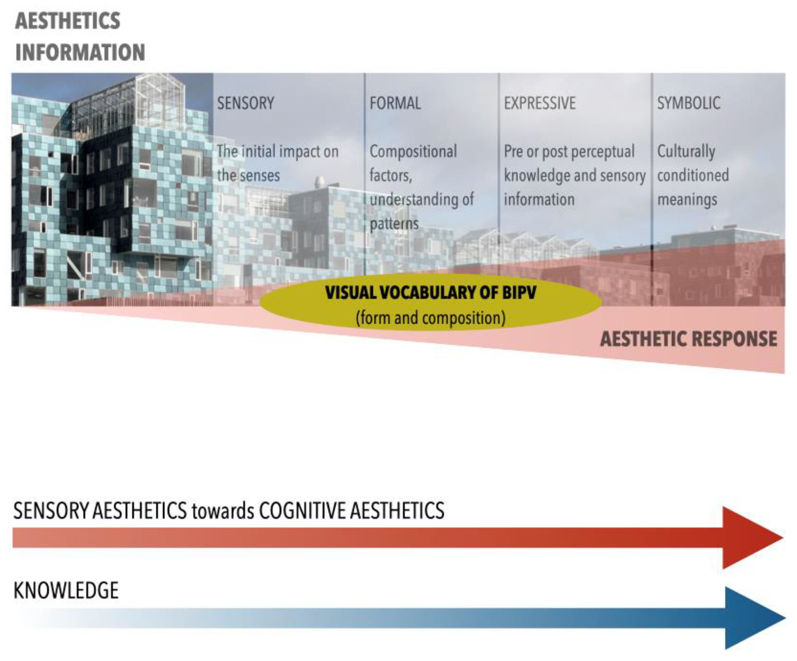
Figure 2.
Definition of a BIPV system as a visual object by understanding how subjective interpretation are formally structured in a tree hierarchical description. Formalization of a hierarchical configuration of the individual visual elements (leaves) into subtrees and trees, to the highest level of a tree, the root node.

Figure 3.
Green Dot Animo Leadership High School, Inglewood, California (USA), 2013. Design: Brooks + Scarpa Architects. On the right: standard (opaque) photovoltaic modules are used. Pictures: © John Linden.
Figure 3.
Green Dot Animo Leadership High School, Inglewood, California (USA), 2013. Design: Brooks + Scarpa Architects. On the right: standard (opaque) photovoltaic modules are used. Pictures: © John Linden.
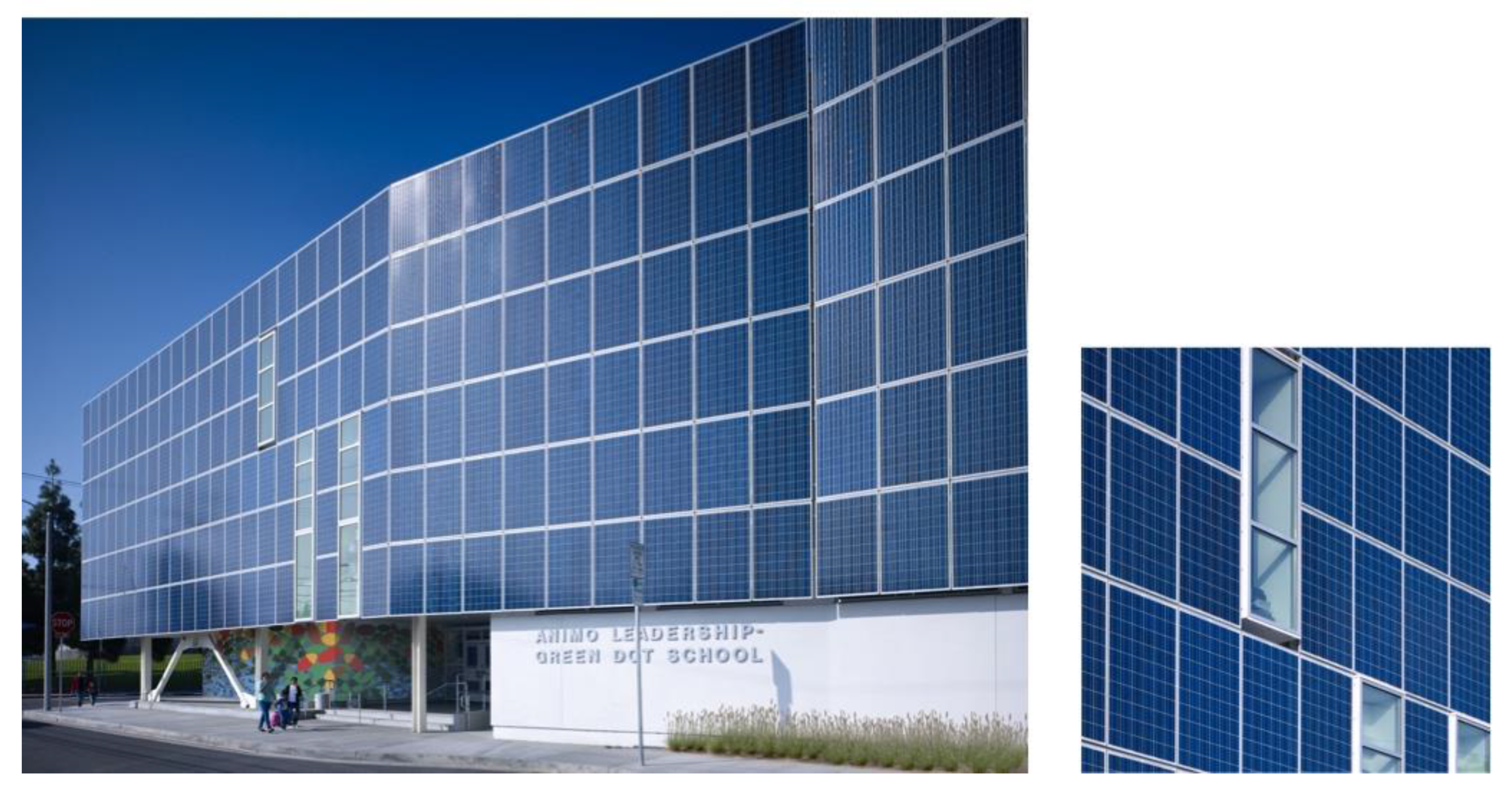
Figure 4.
CMB headquarters, Rome, Italy (2006). Design: 3c+t, Capolei Cavalli architetti associati. In the glazed part of the building’s facade glass–glass photovoltaic modules alternate horizontal areas with transparent glass. In detail: the photovoltaic glass–glass modules are semitransparent, because of the distancing of the photovoltaic cells. Pictures courtesy of Fabrizio Capolei.

Figure 5.
Apartment building on Hofwiesen- and Rothstrasse, renovation and expansion, Zürich (CH), 2016. Design: Viridén + partner. In detail: the facade is composed of a few types (size) rectangular modules showing an opaque, uniform gray surface. Pictures © Viridén + Partner AG, Zürich.
Figure 5.
Apartment building on Hofwiesen- and Rothstrasse, renovation and expansion, Zürich (CH), 2016. Design: Viridén + partner. In detail: the facade is composed of a few types (size) rectangular modules showing an opaque, uniform gray surface. Pictures © Viridén + Partner AG, Zürich.

Figure 6.
NCC headquarters, Solna (SE), 2019. Design: White Arkitekter. In detail: in the curtain wall facade rectangular modules (looking golden with the light conditions of the picture) alternate windows. Pictures courtesy of Rickard Nygren.
Figure 6.
NCC headquarters, Solna (SE), 2019. Design: White Arkitekter. In detail: in the curtain wall facade rectangular modules (looking golden with the light conditions of the picture) alternate windows. Pictures courtesy of Rickard Nygren.
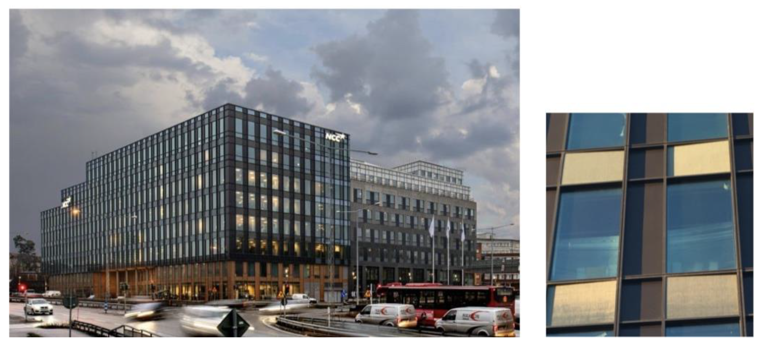
Figure 7.
Copenhagen International School, Copenhagen (DK), 2017. Design: C. F. Møller Architects. In detail: the facade is composed of modules look like opaque greenish surfaces. Pictures © Adam Mørk.
Figure 7.
Copenhagen International School, Copenhagen (DK), 2017. Design: C. F. Møller Architects. In detail: the facade is composed of modules look like opaque greenish surfaces. Pictures © Adam Mørk.

Figure 8.
The building as a composition of spatial elements/tiles (areas) having different shapes, sizes, and colors. The shape and size of the area are not sufficient to suggest the use of photovoltaics in the facade, despite that the tile is compatible with the shape and size of a photovoltaic system.

Figure 9.
The building as a composition of spatial elements/tiles (areas) having different shapes, sizes, and colors. The shape and size of the area are not sufficient to suggest the use of photovoltaics in the facade, despite that the tile is compatible with the shape and size of a photovoltaic system, and despite that the color blue can suggest a compatibility with the use of photovoltaic modules.

Figure 10.
The building as a composition of spatial elements/tiles (areas) having different shapes, sizes, and colors. The shape, size, color, and pattern of the area are not sufficient to suggest the use of photovoltaics in the facade, despite that the tile is compatible with the shape and size of a photovoltaic system, and despite that the color blue and the pattern can suggest the use of photovoltaic modules.

Figure 11.
The building as a composition of spatial elements/tiles (areas) having different shapes, sizes, and colors. The typical texture of the photovoltaic crystalline silicon modules is clear evidence of the use of photovoltaics.
Figure 11.
The building as a composition of spatial elements/tiles (areas) having different shapes, sizes, and colors. The typical texture of the photovoltaic crystalline silicon modules is clear evidence of the use of photovoltaics.

Figure 12.
Photovoltaic glasses show a high variability in the pattern of the cells in the module, and therefore they are less recognizable as photovoltaics than configurations typical of standard photovoltaic modules. The typical texture of a crystalline photovoltaic cell, despite being present, does not have a high discriminating power, as from a distance, the pattern is predominant, since the texture is visible mainly at the photovoltaic cell scale (close distance).

Figure 13.
Variations of the BIPV module visual appearance, based on the use of a semi-transparent or opaque texture as front layer, combined with the use of patterned (crystalline silicon) or uniform (thin films) PV layers and with transparent or colored (opaque) back layers.
Figure 13.
Variations of the BIPV module visual appearance, based on the use of a semi-transparent or opaque texture as front layer, combined with the use of patterned (crystalline silicon) or uniform (thin films) PV layers and with transparent or colored (opaque) back layers.

Figure 14.
The use of an opaque texture on the front side of the PV module allows for a huge variety of visual possibilities and makes the presence of photovoltaics invisible. The texture here presented refers to the innovative PV modules developed at the Lucerne University of Applied Sciences (colors and patterns are printed on the glass surface of these elements, using a digital ceramic printing process). Information available in Reference [39].

Figure 15.
The BIPV visual variations are many. They are based on the use of different layers for the front, the PV, and the back layer of the module. The main elements that play a role in the composition are the type and degree of transparency texture of the front layer, the pattern of the PV layer, and the transparency and color of the back layer.

Figure 16.
The BIPV visual variations are many. A few variations on the front, the PV, and the back layer of the module allow for a significant visual variety.
Figure 16.
The BIPV visual variations are many. A few variations on the front, the PV, and the back layer of the module allow for a significant visual variety.

Figure 17.
The image shows an original illustration from Josef Albers, Interazione del colore, as an exercise on the use of contrasting colors for creating a vibrational effect in the borders of a shape. Here it is used as an image for the visual concept “pattern”.
Figure 17.
The image shows an original illustration from Josef Albers, Interazione del colore, as an exercise on the use of contrasting colors for creating a vibrational effect in the borders of a shape. Here it is used as an image for the visual concept “pattern”.

Figure 18.
The grain of a pattern depends on the size of the single spatial units, defined by their borders. The border can correspond to a technological component, such as a frame, but also to the simple perception of the condition of not coplanarity of two adjacent spatial units. In the picture, a detail of the facade of the Copenhagen International School, Copenhagen (DK), 2017. Design: C. F. Møller Architect.

Figure 19.
The image shows an original illustration from Josef Albers, Interazioni del colore, regarding an exercise on the brightness of red and blue.
Figure 19.
The image shows an original illustration from Josef Albers, Interazioni del colore, regarding an exercise on the brightness of red and blue.

Figure 20.
Original illustration of Bruno Munari for “texture”, in Design e comunicazione visiva. Munari proposes that a texture is a way for “sensitizing” a surface (La sensibilizzazione di una superficie) and remarks that a texture is always perceived by the human eye as a homogeneous surface.
Figure 20.
Original illustration of Bruno Munari for “texture”, in Design e comunicazione visiva. Munari proposes that a texture is a way for “sensitizing” a surface (La sensibilizzazione di una superficie) and remarks that a texture is always perceived by the human eye as a homogeneous surface.

Figure 21.
Josef Albers original illustration in Interazione del colore. Adapted by the author for the purpose of showing the effect of transparency, and displaying the visual result given by a double texture.
Figure 21.
Josef Albers original illustration in Interazione del colore. Adapted by the author for the purpose of showing the effect of transparency, and displaying the visual result given by a double texture.

Figure 22.
The perceptional organization of a BIPV system is approached by using a pattern–patch–matrix model. The configuration at the uppermost global level corresponds to the building’s mosaic pattern, whereas the subtrees correspond to the main concepts, through which individual visual elements are grouped.

Figure 23.
Graphical scheme showing the main scales for the descriptive model, and related information contents. Visual perception aspects are approached at the coarse and medium scales, but as any visual result at a broad scale is the consequence of design and technological choices made at smaller scales, at the fine scale, some technical information is given. A visual vocabulary is distinctive of the description at the coarse and medium scales (as it has to be valid for any visual system, and understandable for anybody), whereas a technical vocabulary is used at the fine scale.

Figure 24.
The coarse scale of description. Hierarchical tree formalization of the BIPV system as a part of the building’s mosaic pattern. At this scale, the information is mainly regarding the categorization of the BIPV system as sub-system of the building envelope technology system (architectural knowledge).


Figure 25.
Possible geometries of the mosaic type; author’s elaboration based on Forman, op. cit.

Figure 26.
Hierarchical tree formalization of the BIPV system as a pattern of patches (the PV modules), at the level of the PV patches (medium scale). At this scale, the information is visual and technical. Some information, typical of the fine scale related to the different layer of the modules’ layering is given under the attribute “Texture”. In italics, some qualitative and technical descriptions are given when needed for an explanation of the listed concepts.


Table 1.
Simplified list of the main technological design issues to be faced at the different scales of BIPV, and different information content (visual and technological).
Table 1.
Simplified list of the main technological design issues to be faced at the different scales of BIPV, and different information content (visual and technological).
| Scale | Envelope, Main Visual, and Technological Design Issues |
|---|---|
| Coarse The building envelope technology systems are described. Where and how the BIPV system is integrated. | Building Envelope Technology Systems Topology Roof, facade, external integrated device. Morphology Rainscreen facade, double-skin facade, curtain wall, window, and masonry; discontinuous roofing, continuous roofing, and atrium/skylight; parapet, balustrade, canopy, and solar shading. |
| Medium The building envelope technology subsystems are described. The BIPV description entails how the BIPV system is integrated, the main features of the module. | Building Envelope Technology Subsystems Sub-technological subsystems. PV modules and framing systems. |
| Fine The building envelope technology sub-systems are described. The BIPV description entails how the PV module is realized so as to get a desired visual effect (components and materials). | Building Envelope Technology Components and Materials Building envelope technological units. PV modules. Visual/technical description of the PV modules. Front layer (pattern and transparency degree) PV layer (technology and pattern) Back layer (color and transparency degree) |
Table 2.
Visual concepts for a vocabulary of BIPV, definitions and specific features, and links to the technological elements of a BIPV system. In italics is what is pertinent to the photovoltaic technology description.
Table 2.
Visual concepts for a vocabulary of BIPV, definitions and specific features, and links to the technological elements of a BIPV system. In italics is what is pertinent to the photovoltaic technology description.
| Visual Concepts | Visual Parameters Definitions and Specific Features |
|---|---|
| Pattern | Specific arrangement of spatial elements, often used synonymously with spatial structure or patch structure. |
| Pattern is the arrangement of the patches. At the BIPV system scale (medium scale), this is the spatial arrangement of the photovoltaic modules into the BIPV system; at the module scale (fine scale), this is the spatial arrangement of the photovoltaic cells into the photovoltaic module. | |
| Geometry | The geometry of a pattern can vary, being irregular or irregular. In most cases, due the constraints imposed by the technology both at the system and at the modules scale, the typical geometries of photovoltaics are regular. Mainly these are based on parallel stripes compositions, or on grid compositions. The variable is the distancing between the stripes and/or the distancing between the cells. |
| Density | In general, in order to allow for the maximum density of power, the photovoltaic modules are characterized by a dense pattern. Nevertheless, porous patterns can be used if a certain degree of transparency is required. The measure of the “pore” space defines the degree of transparency of the component. |
| Patch | Surface area that differs from its surroundings in nature or appearance. |
| At the building scale (coarse scale) this is the whole BIPV system; at the BIPV system scale (medium scale), this is the PV module; at the module scale (fine scale), this is the single cell (if present and visible). For all the elements the description and the assessment are both qualitative and quantitative. | |
| Size | |
| Shape | |
| Position | |
| Border | |
| Color | |
| Transparency | |
| Texture | |
| Matrix | Background cover type in a landscape, characterized by extensive cover and high connectivity; not all landscapes have a definable matrix. |
| Similarly, to landscapes, not all BIPV systems have a definable matrix. The matrix is mostly used in this study for describing the space that is in between the modules in a porous pattern, or what is in between the cells in a module. The matrix is therefore strictly related to a porous pattern. An attribute of the matrix is the transparency, as often it corresponds to the use of glass in the BIPV system pattern, or in the BIPV module.St the fine scale, the matrix can be also visible in a porous pattern. For all the elements the description and the assessment are both qualitative and quantitative. | |
| Transparency | |
| Color |
Publisher’s Note: MDPI stays neutral with regard to jurisdictional claims in published maps and institutional affiliations. |
© 2021 by the author. Licensee MDPI, Basel, Switzerland. This article is an open access article distributed under the terms and conditions of the Creative Commons Attribution (CC BY) license (https://creativecommons.org/licenses/by/4.0/).
Share and Cite
MDPI and ACS Style
Scognamiglio, A. A Trans-Disciplinary Vocabulary for Assessing the Visual Performance of BIPV. Sustainability 2021, 13, 5500. https://doi.org/10.3390/su13105500
AMA Style
Scognamiglio A. A Trans-Disciplinary Vocabulary for Assessing the Visual Performance of BIPV. Sustainability. 2021; 13(10):5500. https://doi.org/10.3390/su13105500
Chicago/Turabian StyleScognamiglio, Alessandra. 2021. "A Trans-Disciplinary Vocabulary for Assessing the Visual Performance of BIPV" Sustainability 13, no. 10: 5500. https://doi.org/10.3390/su13105500
Note that from the first issue of 2016, this journal uses article numbers instead of page numbers. See further details here.