1. Introduction
The global environmental crisis presupposes a new innovative push in the construction sector, mainly aimed at reducing energy consumption and exploiting energy resources from renewable sources. This need had already emerged with European Directive 2002/91, which invites looking at a new generation of nearly zero-energy buildings and, at the same time, work on the reduction of polluting emissions toward the study of multifunctional facades capable of interacting with the environment and the user.
To get to this goal, two issues are identified: the improvement of the performance of the building envelope and the use of very efficient equipment for space cooling and heating. The former has larger relevance in the Mediterranean area, where the project of the shading system plays an important role as it allows for drastically reducing solar gains. The use of responsive elements, which have a wider spectrum of performances, could be useful for improving comfort conditions in indoor or even outdoor spaces. This paper presents an innovative prototype called SLICE, which concerns research on adaptive building envelopes established at the University of Catania for several years. The development of the SLICE prototype is part of a national research project called EWAS—An Early Warning System for Cultural Heritage.
In this research, the use of SLICE in the context of office buildings is also tested.
SLICE is an acronym for “Solar Lightweight Intelligent Component for Envelopes”. The word “adaptive” refers to the ability of some artifact to keep any change of the boundary space and to react to them dynamically. According to this definition, it is possible to imagine an upgrade in the performance of the building envelope by integrating an intelligent system into it. This device could reduce energy consumption [
1] by controlling daylight, shading, and natural ventilation. Therefore, the building envelope can be designed “as part of a holistic building metabolism and morphology, and will often be connected to other parts of the building, including sensors, actuators and command wires from the building management system” [
2].
The large-scale diffusion of open-source devices, like Arduino, has enforced the research in the field of kinetic architecture, which is characterized by a high degree of flexibility linked to both the flexibility of use, concerning the relationship between man and architecture, and the temporal one (i.e., in the architecture–environment interaction) [
3,
4,
5,
6,
7,
8,
9].
As such, the façade is going to become an active building component, able to interact with the boundary environment, which acts in such way to do the following (
Figure 1):
Assure the airtightness and vapor permeability;
Guarantee the indoor air quality, taking advantage of natural ventilation;
Emphasize the natural daylighting in indoor spaces;
Control the solar gain and reduce the heat losses through enhanced thermal insulation;
Guarantee soundproofing.
The required performances depend on the climatic conditions, type of the building (shape and orientation), energy exchanges, and finally the type of façade [
10].
Focusing on this last point, it is possible to define two main types of façades [
11]:
- −
Opaque facades, which are mainly formed by masonry, stone, precast panels, steel cladding, and insulation packages. These kinds of façades have windows and doors with normal dimensions for the passage of air and light.
- −
Transparent facades, also called continuous façades, which are formed by large glass transparent or translucent elements with a steel loadbearing frame.
Therefore, the façade brings the ability to add new functions, such as new solutions to reduce energy costs [
12] or improve the production of renewable energy [
1,
3,
4,
5,
6,
7,
8,
9,
10,
11,
13,
14,
15,
16,
17,
18,
19,
20,
21,
22,
23,
24,
25]. In this way, the façade has been transformed into a very complex system, surpassing the traditional concepts.
The first example in this direction to be considered is the southeast façade of the Stadtwerke of Aachen, realized in 1991 [
23]. It was formed with semi-transparent photovoltaic glass–glass silicon modules with a double role: to produce energy and to assure thermic insulation [
23]. It also marks the beginning of building-integrated photovoltaics (BIPV), with the acronym referring to the integration between the modules for the production of electricity and the design of the architectonic skin [
14].
During the 1990s, it was possible to note the development of several intelligent systems for the architecture, which took advantage of the new possibility offered by both automation and computational science. Among them, there was the Neutral Network House of the University of Colorado, which was able to analyze the attitudes of the users (e.g., regulation of indoor temperature and regulation of light level) in order to anticipate their needs [
20]. The last aim of the system was to reduce the energy cost thanks to the ability to activate the heating, lighting, and shading system in time with the actual necessity [
19].
In this approach, the inputs, which come from the outside (i.e., from the boundary environment) or from the inside (i.e., from the occupants), give commands to the kinematics building envelope components, which can produce moments (mainly translations or rotations) or transformation of the physical characteristics of the material (e.g., dimensions, transparency, or similar). In this view, it is possible to define three macro-categories of adaptive façade systems [
11]:
The first group is formed by the materials, which are significantly able to modify their proprieties under the effect of external stimulations (e.g., temperature variation or electric or magnetic field variation). This ability for variation, which can be reversible or permanent, induces the “smartness” of the material. It is possible to individuate some sub-categories:
- −
Igro-morphic materials (Hygromorphic Materials (HMs));
- −
Thermo-bimetals (Thermo-Bimetals (TBs));
- −
Shape memory leagues (Shape Memory Alloys (SMAs));
- −
Shape memory polymers (Shape Memory Polymers (SMPs)).
As for the second type of façade, the attitude to refer to the word “intelligent” for buildings sprang up between the 1960s and 1970s, when the application of automation to cooling and heating systems allowed the possibility to design a comfort zone with a different set-up. Successively, the word intelligent has referred to the skin, with new meanings, to take into consideration the abilities of the envelope to have an active role in the regulation of comfort conditions and energy consumption through predictive behavior [
25]. The system must be able to react to the environmental conditions or to the actions of the occupants after the interpretation of them to adjust the indoor comfort conditions [
24]. Therefore, the “intelligence” of the intelligent building skin is realized through a wide, complex series of lamellae, slots, actuators, sensors, microcontrollers, and so on. It is also appropriate to focus on the concept of “interactivity”, even if it is generally addressed to the art installation more than the architecture. Interactive systems can interact with people, for example, to execute some automatic functions by following a human command. The subtle difference has led to delimiting the interactive design as a subset of the intelligent one [
25].
The third group, called responsive façade systems, represents the evolution of the preceding ones. In it, the skill to adapt itself in real-time to the environmental conditions and the needs of the users add up to the ability to interact with the occupants and to predict their needs. The embodied algorithms make the system able to learn by the inputs of the users, maintaining a continuous conversation with them to adapt the building to new optimal configurations [
11,
23,
24].
This paper constitutes an enhancement of the research, called SLICE. In the previous steps, the prototyping of the base material of a novel active shading system for an adaptive building envelope was defined and described. One of the features of this shading system is its modularity, connected to its lightness, which allows us to use it both for new and existent buildings. In fact, the use of an adaptive component for facade envelopes, seen as a retrofit solution for existing buildings, is more suitable for improving the comfort conditions of environments, such as in office buildings, schools, or sports facilities, where user interaction can often be bypassed [
15]. This manuscript consists of the following parts. After the introduction, the state of the art it is described, focusing on both the responsive, adaptive, and intelligent façade elements and the integration of photovoltaic cells. After this, the materials and methods are shown, concerning the realization of the kinematics for writing the automatization and control code and the prototyping phases. The description of the main issue follows this, mainly addressing defining the movement, the operating modes, the hardware, and the functional tests. The discussion of the main results completes the manuscript, and the conclusion closes it.
2. State of the Art
The actions of a shading system, rather than being exclusively predetermined by the designer, change continuously by measuring the user’s reactions to their responses. As clarified by Velikov and Geoffrey [
25], a responsive envelope includes the functionality and performance of an “intelligent” system with real-time sensing, climate-adaptive kinetic elements, intelligent materials, automation, and user exclusion capabilities, but also interactive features. This means there is the possibility for the occupants to physically manipulate elements of the building envelope to control environmental conditions, as well as computational algorithms that allow the building system to self-regulate and learn over time. It should be considered that BIPVs are increasingly used [
22], despite the presence of the photovoltaic system on the façade, representing the less effective alternative to rooftop solar PV due to the difference in radiation between the horizontal and vertical surfaces [
26]. To improve the performance of these systems, it is useful to adopt adaptive approaches and therefore link them to the “intelligence” of the components of the envelope (Freitas et al., 2020). Using this kind of solution, it is possible to modify the photovoltaics’ orientation through solar localization mechanisms, combining the advantages of integrated solar monitoring aimed at producing energy with adaptive shading and thus obtaining considerable reductions in thermal loads [
6]. The achievement of this objective has led to the development of interesting solutions reported in the scientific literature.
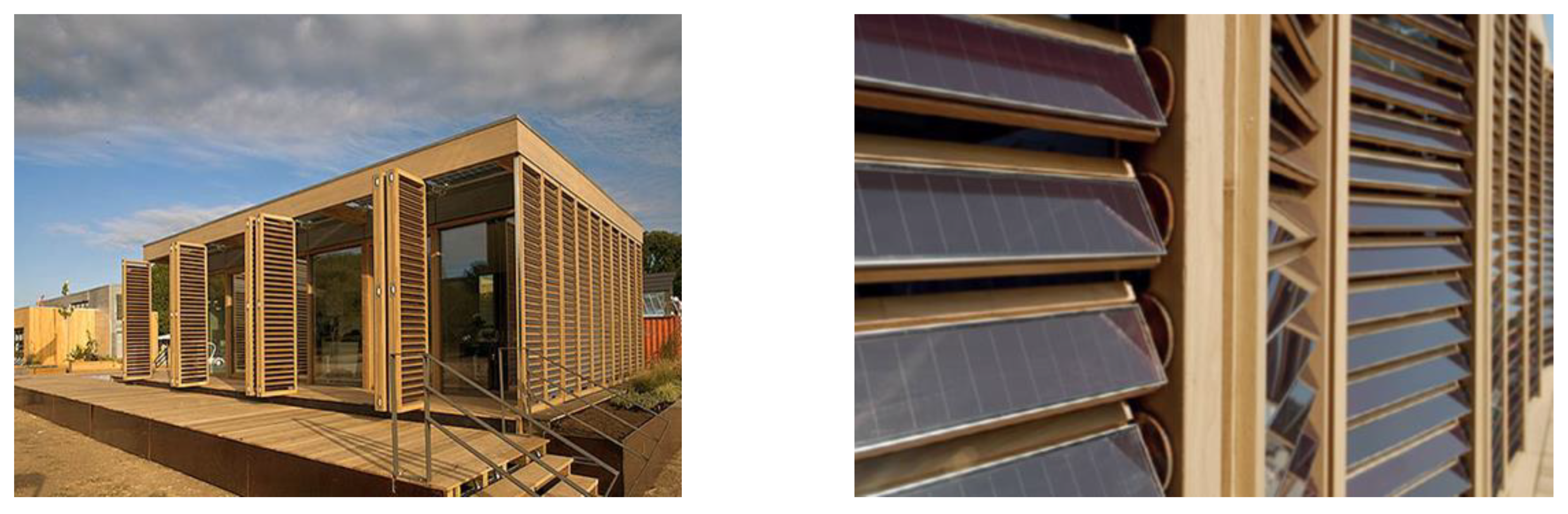
As an example, the Technische Universität Darmstadt experimental house, built for the 2007 United States Solar Decathlon Competition (
Figure 2), incorporates an external cladding consisting of wooden slits with integrated photovoltaic panels controlled by an intelligent system, allowing the production of energy and at the same time the reduction of solar gains [
25].
On the other hand, the Adaptive Solar Skin system was born as a self-supporting facade system for existing buildings. It is a double skin consisting of individually orientable photovoltaic panels connected to a mechanical driver programmed to track daylight sunlight. The kinematics of the single rows of panels allows for reaching an efficiency rate higher than 40% compared with fixed solutions (
Figure 3) [
6].
ETH Zurich has developed a system called the Adaptive Solar Facade (ASF), a modular facade with an integrated photovoltaic system made with individually adjustable devices (
Figure 4). In this case, the basic component consists of a dynamic and multifunctional shading panel with two degrees of freedom, made with a 0.8-mm thick aluminum substrate for the thin-film photovoltaic module, to which a soft pneumatic actuator is installed, which connects it to the support frame of the entire facade and the network of cables. Each module has a total weight of 800 g [
4]. The group of granular façade elements thus conceived provides shading, electricity generation, and daylight distribution. Each module can act autonomously thanks to light sensors, but it can also be grouped into small groups and controlled by a central management system.
A responsive facade system based on concentrating solar collectors called the Integrated Concentrating Solar Facade (ICSF) was studied at the Center for Architecture, Science and Ecology, an internal research center at Rensselaer Polytechnic Institute in New York. The individual pyramid-shaped suspended glass modules can capture 85% of sunlight by moving around a pin, rotating around the horizontal and vertical axis to respond to the path of the sun and maximize the natural lighting [
5]. The structure of the pyramidal glass is particularly complex because it is characterized by a primary (POE) and secondary optical element (SOE), a highly efficient concentrator photovoltaic cell (CPV), and a water heat exchanger (HX). Thanks to its flexibility, the system is not only suitable for the construction of facades but also for the construction of horizontal screening systems (
Figure 5).
The previous cases allow for identifying in the kinematics of modular elements the real weak point of adaptive and responsive facade solutions. The necessity to delegate multiple movements or functions to the individual components often involves the adoption of complex actuation systems, which can lead to problems related to their maintenance and reliability. For this reason, some research groups have addressed their attention in the opposite direction, looking at the adoption of smart materials or materials with one or more properties that can be modified through external stimuli. The Adaptive BIPV Facade (
Figure 6) adopts particular blades capable of changing their curvature concerning external environmental conditions [
18]. The device is activated by the different hygroscopicity of the two layers of wood that constitute it, because the wood expands and contracts when the relative humidity varies, making it autonomous in a simple way; the relative humidity is higher in the morning at dawn and decreases during the day. It usually reaches a minimum in the late afternoon. It grows again during the night, allowing the tracking system to take on an adequate curvature during the day.
The general aim of the research for SLICE is the development of an innovative responsive shading component, which includes power production through the integration of flexible PV cells. This device can assume different configurations thanks to a computerized system of actuators and sensors. These peculiarities make it suitable for various applications, such as adaptive shading systems, pavilions, and light roofing of open spaces in sensitive areas.
The state of the art on the use of responsive building envelopes has suggested focusing attention on materials and technologies in parallel with the selection of the kinematics mechanisms [
27]. For achieving responsiveness, foldability has been identified as a suitable system because it gives the surface a high degree of transformability connected to its kinematics and, at the same time, it allows for an increase in mechanical performance [
17,
28]. The fold gives the material in the direction of the same stiffening, which takes the name of “resistance by shape” [
21].
This article presents the test campaign conducted under controlled environmental conditions on a full-scale prototype. The survey phases have allowed testing the kinematics and the material subjected to mechanical stress, verifying the automation and management system.
3. Materials and Methods
3.1. Material
The first part of the research addressed the development of a composite material, realized with reinforcing fiber. In particular, glass fiber fabrics and Biotex Flax, a fabric made up of flax fibers, and a thermoplastic elastomer (TPE) matrix, a material that retains the lightness and versatility characteristics typical of textiles (Rodonò, Monteleone and Sapienza, 2021), were tested.
The mechanical tests carried out evidenced that the composite material had properties comparable with those of the composite materials commonly used in textile architecture (Rodonò et al., 2019). The proposed device was equipped with photovoltaic cells, which generated the power requested for its handling under stand-alone applications.
High-efficiency monocrystalline silicon solar cells with dimensions of 125 mm by 125 mm, manufactured by SunPower Maxeon®, were utilized. As this type of product is equipped with back-contact technology, it was suitable for withstanding the stresses generated by the flexibility of the composite substrate.
The final stratigraphy was made up of a lower layer in the EVA produced by “SKC films” of the EF2N type and a reinforcement fabric in Biotex, the interposition of the photovoltaic cells between the two upper layers of the EVA.
To optimize the integration of the photovoltaic cells into the composite, a final coverage of the photovoltaic cells made by the DUN-SOLAR PPE was introduced. The DUN-SOLAR PPE is a multilayer laminated panel in polyester that is extremely waterproof, with excellent resistance to atmospheric agents and dirt as well as to most chemical compounds. It is usually used as a coating layer in the production of photovoltaic modules.
3.2. Automation and Kinematics
The first phase of this research project addressed the design of the earliest prototype at a 1:1 scale (
Figure 7) called SLICE 1.0, which consisted of a simple fold sample whose dimensions were 20cm × 40 cm and a weight of 139 g, made with an EVA matrix (inner and outer layer), fiberglass reinforcement, two photovoltaic monocrystalline silicon cells, and a protection layer of PVF. Only the operating cycles of the components were investigated [
8].
A battery charging circuit and a lithium battery completed the architecture of SLICE 1.0. The automation and control system was determined to be an Arduino board, equipped with reading inputs for control buttons, a limit switch, a I2C sensing chip for monitoring the voltage and charge-discharge current on the battery, the voltage and current of the load (gear motor), and the current of the two photovoltaic cells. The circuit was equipped with a step-up voltage regulator circuit, which brought a battery output voltage of 3.7 V to the input power voltage in the Arduino circuit at 5.0 V. The components of SLICE 1.0 are shown in
Table 1.
To program the electronic device, the multi-platform software environment Arduino IDE was used.The programming code developed for the prototype SLICE 1.0 allowed for the first simulations in the laboratory and improvement of the components and handling systems [
29].
The programming code was developed considering some packet instructions that were given by the microcontroller to the handling group for the interpretation of specific external inputs. This task required a preliminary study of the sensors to identify the ones most suitable for the project.
The tuning phase was carried out through an experimental test conducted under variable environmental conditions. Therefore, the calibration of the sensors and their tuning were performed via opening and closing cycles, and the system’s power supply and charging were also tested. The control code was written in Arduino IDE, based on Java code which, using a simple and intuitive programming language derived from C and C ++, allowed for easy writing of programs even for inexperienced users. Before the advent of hardware platforms such as Arduino, the hardware and software prototyping phases of automated systems were expensive and very complex [
30].
The tests on the basic automatism and the charging system paved the way for the creation of a second scale model of the real SLICE 2.0 prototype, through which a series of tests in real environmental conditions were carried out.
3.3. Prototyping
The enhanced prototype, called SLICE 2.0, had dimensions of 100cm × 68 cm and a weight of 1.5 kg, dimensions comparable with those of the standard frame size of a window. The reinforcement layer was made with Biotex Flax, with a 400 g/m
2 twill texture. The matrix was made with Ethylene-vinyl acetate (EVA), and a layer of PPE [
8] were added for the protection of the photovoltaic cell. Twelve cells divided into four strings were included in parallel with each of the three cells in series.
The composite material underwent a thermoforming process using metal conformers. The achievement of the glass transition temperature Ts of the polymer, the consequent deformation of the material according to the folds imposed by the metal support, and the gradual cooling of the material represent the phases that determined the configuration with a bellows pattern, with 5 folds and 6 panels of 16.5 cm × 68 cm each.
Therefore, the prototype consisting of a fabric panel was equipped with an adjustable wooden support frame that allowed for its position on an existing window as an adaptive shielding component (
Figure 8).
4. Description
4.1. Movement
The mechanical system was based on linear guides for 3D printers, the carriages of which were fixed to a pair of belts for synchronizing motion, moved by 4 pulleys in aluminum, one of which was directly fixed to the shaft of a gear motor [
8]. Specifically, for the handling of the fabric panel, considering the larger dimensions and the relative weight, it was necessary to reinforce the guide system and install intermediate sliding carriages, obtained by 3D printing with PLA.
The rapid prototyping phase of the components was also realized using 5 mm PMMA (polymethylmethacrylate), cut with a CO2 laser cutter, model 6300 WorkLine s.r.l.
The upgrade from SLICE 1.0 to 2.0 also generated interest in the energy storage system for adapting its capacity for energy consumption for the opening and closing cycles during a typical day of use. The energy consumption of the microcontroller in standby, the sensors, and the load of the gear motor during movement were considered. Thus, the previous battery was replaced with a bigger one.
The charging system was implemented with the installation of an additional external module with protection and an LED charge indicator. In this way, using a smartphone charger, it was possible to manage the battery pack even in the absence of sunlight.
The main components of SLICE 2.0 are shown in
Table 2.
4.2. Operating Modes
The code allowed for defining three different operating modes, namely Comfort Mode, Energy Mode and Manual Mode. The addition of a motion sensor made it possible to detect the presence or absence of occupants in the room and, consequently, the system could operate in Comfort Mode or Energy Mode. The Comfort Mode aimed to manage visual comfort conditions within the indoor environment. Specifically, it was possible to obtain automation such as opening and adjusting the opening level of the component, considering reference illuminations as a function of the different use of the environment.
This configuration permitted the production of energy in the event of a low battery charge or even folding up and returning to its seat in the event of adverse weather conditions that could cause damage.
When the sensor did not reveal the presence of users, the Arduino control system activated the Energy Mode, aimed at optimizing energy production through the complete deployment of the shield and ensuring the complete extension of the photovoltaic surface.
The Manual Mode, activated by a dedicated button, allowed for deactivating the automation mode to carry out maintenance or cleaning activities on the window.
Figure 9 summarizes the above-mentioned operating modes, which were tested during the experimental phase.
4.3. Hardware Equipment
Some of the hardware components were updated in the SLICE 2.0 prototype. Specifically, a higher capacity battery was introduced, as it was considered more adequate for the new prototype while the charging circuit for the connection of the sample with the photovoltaic cells was maintained. The battery was connected to a circuit of a step-up voltage regulator circuit to adapt its voltage to that required by the microcontroller. This procedure was also managed through the Arduino board. To speed up the charging phases during the first tests on the functioning of the code, the battery was connected to a micro-USB lithium battery charge board with protection and a charge indicator LED. The following new sensors and components were connected to the microcontroller using a motherboard (
Table 2):
- −
Analogic light sensor for the internal lighting measurements;
- −
Infrared proximity sensor for detecting the presence of users;
- −
Rain or snow sensor for detecting rain or snow events;
- −
Current sensor which supplied a voltage measurement proportional to the current that passed through the photovoltaic system;
- −
LCD display which showed electrical and lighting data and on the operating status.
Figure 10 shows the whole control system circuit of the SLICE 2.0 prototype, which was installed on a remote panel. On the left side of the remote panel are the Arduino microcontroller, the rain sensor, the internal and external light sensors, the infrared sensor, and all the connections with the motherboard. In the middle part of the panel, there are connections between the microcontroller with the motion control relay group (two for the direction of rotation and one for movement initiation) and the gear motor. Finally, the right side hosts the charging system connected to the battery and the voltage step-up circuit.
4.4. Programming Code
The Arduino IDE interface was characterized by libraries, a group of precompiled basic codes that allowed both performing complex operations and managing external devices. The LiquidCristal library, which allowed communication with the Hitachi HD44780 liquid crystal display (or other compatible ones), was used. The data transmission mode was 4-bit to manage a 2-line and 16-column display with the necessary information for monitoring SLICE 2.0. The operating diagram of the developed code is shown in
Figure 11.
The first part of the code declares the variables (i.e., a sort of instruction container where data are stored for later use by the code). Some of these define the Arduino input and output pins for component management, while others retain numeric or binary values. In this code, the variables state and statePushbutton take on particular importance.
The value assumed by the first variable determines the condition of presence or absence of the user in the environment. The second one, on the other hand, identifies the on or off condition of the prototype manual operation button.
The active part of the code is represented by the setup and loop blocks, which are complex groups of variables linked to libraries through instructions. The setup paragraph contains the set of operations performed at the beginning of the program and only one time. In this phase, the operating modes are defined. The initialization of the analog and digital pins, the communication speed of the serial monitor, and the function that activates the LCD display are called up.
The loop paragraph represents the main body of the code. Inside this, all the operations for the complete execution phase of the program are carried out in a continuous cycle. The values corresponding to the voltage of the battery and the photovoltaic cells are acquired, converted, and subsequently stored in the respective variables. The values of the brightness and proximity sensors are also acquired and stored.
Each program cycle begins by checking the status of a mode selection button on the control panel. Pressing this button for 1 s determines the passage of the variable ModeButton to the HIGH value. The blue LED switches on, and the yellow and green LEDs switch off. A value of 4 is assigned to the case variable. This last operation recalls the portion of the code called case 4, corresponding to the manual management of the shield. Otherwise, the LOW value of the button state variable enables the branch of code that queries the motion sensor. What is perceived by this sensor determines the HIGH/LOW value of the pinVal variable (i.e., the execution of the code relating to the automatic Comfort Mode and Energy Mode configurations).
The switch case statement, also known as the multiple instruction function, lets the program control the flow of the component by specifying different portions of code to be executed according to a series of set conditions (i.e., the initial readings of the sensor values).
For the Comfort Mode code section, the analysis of the value returned by the brightness sensor is compared with the illuminance threshold setpoint (e.g., 500 lux).
For illuminance lower than the setpoint, the system recalls the code defined in Case 0, folding the shield for increasing the daylight into the environment until the reference brightness value is reached. Correspondingly, for values between 501 lux and 1000 lux, the system will recall the code defined in Case 1 by also activating manual management within this operating range, or it will recall Case 2 for values higher than 1000 lux. This last scenario corresponds to the rise of a glaring risk. Thus, it determines the full unfolding of the shield to the ideal condition until the reference brightness value is reached.
The motion sensor, after 45 s from the last detection of human presence in the environment, sets its digital output to
LOW, which determines the activation of the Energy Mode code section, recalling the code of Case 3. Case 3 keeps the shield deployed to ensure maximum exposure of the photovoltaic surface. The management adaptive procedure of SLICE 2.0 is shown in
Figure 11.
4.5. Functional Test
A test campaign was carried out on the SLICE 2.0 prototype to validate the functioning of the system during March in Catania (latitude 37.54, longitude 15.07).
The surveys were conducted in two office rooms, as this kind of application could be more suited for testing the characteristics of a responsive component. These rooms had a surface of 20 m2, both with a window of 120 cm × 140 cm oriented at the southern “South Room” and the western “West Room”.
The experimental surveys were carried out on the 13–14 March 2020 for the “South Room” and the “West Room” during almost sunny days.
Figure 12 shows the global, direct and diffuse components of solar irradiance during a typical day in March derived by the PVGIS website.
The chain of measurements allowed for monitoring the value of the voltage produced by the solar cells installed in the shield, as well as the brightness measured by the sensor installed within the room on the writing desk.
Regarding the conversion of the measurements in lux, this was previously defined using a linear regression during the calibration phase.
Figure 13a shows the variation of the illuminance measured within the West Room as well as the solar irradiance that hit the solar cells. It is possible to observe that the illuminance increased during the first part of the day, reaching a peak of 789 lux at 16.15. Afterward, it diminished following the time variation of the solar irradiance that hit the solar cell. The coherence between these two sets of data highlights the right operation of the chain of measurements.
Figure 13b shows the variation of the measured voltage. A rather constant trend with voltage values close to 1.8 V was observed up to 5:45 p.m., and afterward, a sharp decrease was observed. Once again, such a result is coherent with the illumination of the PV cell.
The value of 1.8 V corresponded with the expected value of the three cells connected in series. Indeed, each cell had to generate a tension of about 0.6 V. The decrease observed in the second part of the day could be attributed to the increased cell temperatures.
Figure 14a shows the variation of the illuminance measured within the West Room as well as the solar irradiance that hit the solar cells. Although some fluctuations of illuminance occurred, it is possible to observe an increasing trend, with a peak of 1821 lux at 2:45 p.m., and afterward, the illuminance diminished following the time variation of the solar irradiance that hit the solar cell. The coherence between these two sets of data highlights the right operation of the chain of measurements.
Figure 14b shows the variation of the measured voltage, which was about constant and close to 1.8 V, corresponding with the expected value. At the end of the day, when the solar irradiation fell, the expected sharp decrease of the voltage was not detected, so it is possible to argue that something did not operate in the right manner.
The results of the above-mentioned tests highlight the satisfactory functioning of the SLICE 2.0 prototype.
5. Discussion
Further tests were carried out for checking the effectiveness of the different possibilities of the SLICE 2.0 operating modes. On the afternoon of 14 May 2020, the prototype was installed in the West Room, and an IP camera was mounted to monitor the components, while for recording the data from the sensors and reading the activated code parts, the Arduino board was connected to a PC used as a serial monitor. The first phase of the test involved the Energy Mode. In absence of people, the component was unfolded and remained fully deployed, taking advantage of the whole active surface until people moved into the room.
Future prototype upgrades have to foresee improvements of the Energy Mode’s operation. In fact, considering the variation of the sun’s zenith and azimuth angles during the day, it is necessary to integrate the Arduino board with an additional algorithm that allows the positioning of the cells to the optimal incident angle for power production.
By activating the Comfort Mode, the SLICE 2.0 prototype changed its conformation by instantly moving to the folding position, allowing illumination of the room. The variation of internal brightness was simulated by shading the brightness sensor for a few minutes; thus, the immediate folding of the component was observed until the pre-established internal lighting level was reached. The Manual Mode was tested, operating the folding and unfolding cycles manually with the opening and closing controls.
At sunset, the Comfort Mode was restored, with consequent automatic folding of the component. When the limit value of 500 lux was reached, the component stopped its movement. Finally, all users freed up the room, and after a few minutes from the IP camera, it was possible to observe the automatic activation of the Energy Mode, with the consequent total deployment of the shielding element.
The results obtained during the experimental phase highlighted some limitations of the SLICE 2.0 prototype. It was observed that the charging board did not allow obtaining an increase of the produced energy proportional to the number of PV cells installed. This highlights the low efficiency of the system. For this reason, it was decided to modify the recharging system by installing an MPPT circuit to allow the photovoltaic cells of the component to operate at their point of maximum power.
6. Conclusions
This study illustrates the design of an adaptive envelope component, namely SLICE, or the Solar Lightweight Intelligent Component for Envelopes, which is capable of being energy self-sufficient. SLICE is a lightweight and stand-alone component for dynamic envelopes consisting of a flexible composite material where high-efficiency photovoltaic cells are integrated.
This paper describes the design process that led to the realization of the current prototypes and the first test phase carried out in the laboratory. The first part of this research describes the programming of the management and control system, which is based on the Arduino platform.
The adaptivity of SLICE was obtained through three different operating modes, called the Energy, Comfort, and Manual modes, which allowed for modifying the SLICE configuration to obtain maximization of the energy production, control of the internal illumination, or a configuration freely chosen by the users.
The second part of this study showed some preliminary tests carried out under real environmental conditions. These experimental tests highlighted the effectiveness of the programming code.
In particular, the SLICE prototype allowed the following advantages: reducing the solar gain, maintaining the requested illumination of the room, and consequently, contributing to the improvement of the indoor comfort conditions. Thanks to its responsivity, SLICE operated in such a way to optimize energy production when there were no people in the room. In this case, the SLICE device was fully unfolded for improving energy production and to reduce the cooling load of the room.
The tests also highlighted some constraints of the SLICE 2.0 prototype. It was observed that the charging board did not have suitable dimensions, and as a consequence, it was not possible to store the energy produced by the PV cells. For this reason, the development of this research foresees the redesign of the recharging system and also the addition of an MPPT controller, which will allow the photovoltaic cells to operate at their point of maximum power.


