1. Introduction
In the last years, integrated renovation of existing building stock has become a strategic aspect of economic and environmental policies [
1]. Several studies agree that residential existing buildings built before 1990, i.e., before the enforcement of most EU energy regulations, are currently responsible for 40% of the final energy demand and for approximately 36% of greenhouse gas emissions [
2,
3,
4,
5,
6]. In addition to the energetic problem, the seismic vulnerability of the existing buildings stock is also a critical issue since nearly 50% of the European territory is earthquake-prone [
1].
Focusing on the Italian scenario, around 86% of the residential stock was built before the enforcement of the 10/1991 Law dealing with the reduction of energy consumption in buildings and around 50% of the residential stock is characterized by a high seismic vulnerability since it was built before the enforcement of seismic codes [
7,
8]. These energy deficiencies and seismic vulnerabilities are typically associated with a general aging of the building stock which is more than 35% over 50 years old. From a structural point of view, it means that about a third of existing buildings have reached their nominal service life, exhibiting structural deficiencies for both vertical and horizontal loads [
9]. In addition, the poor maintenance of the building stock induced an urban decay, resulting in a loss of the economic values of the building stock [
10].
There are two possible intervention option to remedy energy deficits, seismic vulnerabilities and architecture of the existing building: retrofit or demolish and reconstruct the building. Generally, the first option entails lower embodied energy, global warming potential, and economic impact, as well as shorter relocation time, thus proving to be more sustainable [
11]. In contrast, demolition and reconstruction should be preferred only when retrofitting solutions are not economically and technically advisable [
11,
12,
13,
14]. It is worth nothing that the issue of non-interruption of use of the building is critical to allow an adequate diffusion of retrofit interventions.
Different intervention techniques have been developed in recent decades for energetic or seismic retrofit of existing buildings. However, these interventions reach energy and seismic targets in a decoupled way generating high intervention costs and high occupants’ disturbance. According to these remarks, new integrated refurbishment techniques have been recently developed by companies and researchers in order to make combined renovation more environmentally, economically, and socially sustainable and less disruptive [
15].
Within this framework, this paper proposes an eco-friendly and sustainable RC-framed skin for integrated refurbishment of existing buildings. Firstly, to better understand the overall topic, a review of the state of the art of traditional and innovative energy and seismic renovation interventions for RC-framed buildings is presented.
Then, a preliminary description of the proposed RC-framed skin technology is provided with particular attention to the simultaneous improvement of structural and non-structural performances. Technological details and in situ installation phases are described with special regard to connection and interaction with the existing building.
Procedures for the multidisciplinary assessment of building upgrading, in terms of seismic capacity and thermo-hygrometric and acoustic performances are defined and applied to a selected basic cell structure extracted from a representative existing building. The feasibility and sustainability of the proposed upgrading intervention is finally investigated by means of a holistic Life Cycle Assessment (LCA) for environmental impact and Life Cycle cost (LCC) for economic costs. Hence, considering the proposed retrofitting intervention, a cradle to gate analysis is carried out to preliminarily evaluate the carbon dioxide equivalent (CO2-eq) emissions and economic impacts related to the construction phase (i.e., consumption of raw materials, energy, transport, labor).
2. Proposed RC-Framed Skin for the Upgrading of Existing Buildings
In this section, after a brief review of the recurring techniques for energy and seismic renovation interventions, the proposed RC-framed skin technology is thoroughly described, also providing a description of the in situ installation phase, highlighting the peculiarities and advantages of the proposed system concerning the issues of the invasiveness and interruption of use of the building.
2.1. Overview on Combined/Integrated Systems for Energy and Seismic Renovation Interventions of RC Frame Buildings
In this section, a brief overview of the existing systems for energy and seismic renovation interventions is reported. First of all, the existing systems can be broadly divided in two categories [
1]. The first category is related to those systems that combine energy and seismic renovation interventions in an additive way, i.e., superimposing two separate interventions; the second category is related to those systems that integrate energy and seismic interventions within a unitary technological system.
The former category is more traditional and has among its advantages the possibility to implement the distinct interventions in different periods. Typical interventions that reduce energy demand are the application of insulating materials on vertical surfaces and roofs, often together with the substitution of existing windows with high-performance ones. Other possible interventions include the installation of shading devices aimed at reducing the solar radiation and improvement of the efficiency of systems (for heating, ventilation, air conditioning, etc.). Interventions that improve the seismic performances can be separated into local and global interventions. Local interventions consist of the reinforcement of some of the existing structural elements (typically columns, beams, and beam–column joints) by means of steel, RC, or, more recently, fiber-reinforced polymer (FRP) jacketing. More recently, textile-reinforced mortar (TRM) has been considered as an alternative to FRP jacketing to overcome some of the limits of this material (i.e., poor behavior at high temperature, poor fire resistance, difficulty in application at low temperatures or wet surfaces, etc.) Global interventions consist of the construction of new lateral load-carrying systems such as, for instance, RC shear walls or steel braced frames; more recently, the possibility of exploiting timber shear wall, and particularly cross-laminated timber (CLT) shear walls, has been under investigation [
16]. These techniques are often invasive, time-consuming, and expensive. In the case of global interventions, another critical aspect is relative to the requirement of the improvement of the foundation system. Finally, a further possibility to improve the seismic behavior is represented by techniques aimed at reducing the seismic demand by means of seismic isolator installed between foundation and structure. These techniques are not always applicable due to the required distance between near buildings; moreover, high costs are often associated with these techniques.
The integrated systems for energy and seismic renovation interventions are more recent and often they are represented by innovative retrofitting technologies that require the installation of seismic-resistant systems outside of the building; this is a very important aspect since the interruption of the use of the building during the intervention is avoided, meaning that none of the activities inside the building (e.g., residency, working office, etc.) are affected by the interventions. Among these solutions, Bournas [
17] investigated an innovative intervention for existing RC frame and unreinforced masonry buildings represented by TRM strengthening coupled with installation of insulating materials and heating systems. Ecosism s.r.l. recently introduced an integrated and low-invasive solution developed in collaboration with the University of Padua [
18,
19,
20] that consists of the creation of a new external envelope represented by RC wall cast in situ between one or two prefabricated layers of insulating material. This outer envelope skin is designed to carry the whole seismic action. Another solution proposed is the replacement of the infill walls with autoclaved aerated concrete (ACC) blocks exploiting both thermal and mechanical performance [
21]. This technology is indicated obviously only for RC frame constructions with masonry infill. Ferrante et al. [
22] investigated an integrated solution based on earthquake-resistant exoskeleton; particularly, they proposed the use of a new envelope constituted by prefabricated components of steel braced frames that create new living spaces. D’Urso and Cicero [
23] worked on the idea of external steel exoskeletons to propose a parametric procedure to define multiple retrofitting alternatives. Marini et al. [
24] and Manfredi and Masi [
25] investigated systems based on an engineered double-skin. Particularly, Marini et al. [
24] proposed a technological double skin exoskeleton that integrates structural and energy functions with the possibility of introducing dissipative elements to further improve the seismic performance. Manfredi and Masi [
25] proposed the use of new RC infilled frames connected to the existing ones.
More recently, cross-laminated timber (CLT) panels have been considered as a valid alternative for the energy and seismic restoration intervention for existing RC buildings. CLT is particularly promising because it is an engineered wood product that on one hand is characterized by good thermal performance due to the low thermal conductivity, and on the other hand by its high strength and stiffness. To further improve thermal efficiency, additional insulating materials can be coupled to CLT panels. In particular, the possibility of replacing existing masonry infill walls in RC frame buildings with CLT panels has been investigated by Stazi et al. [
26]. Despite the potential of this technique (in particular, speed of installation, reduced cost, low invasiveness, environmental sustainability, reversibility of the intervention), the research is still at a preliminary stage and needs further investigation.
2.2. Description of the Proposed RC-Framed Technology
The proposed technology for the integrated refurbishment is based on the idea of cladding an existing multi-story building with an eco-friendly and sustainable RC-framed skin.
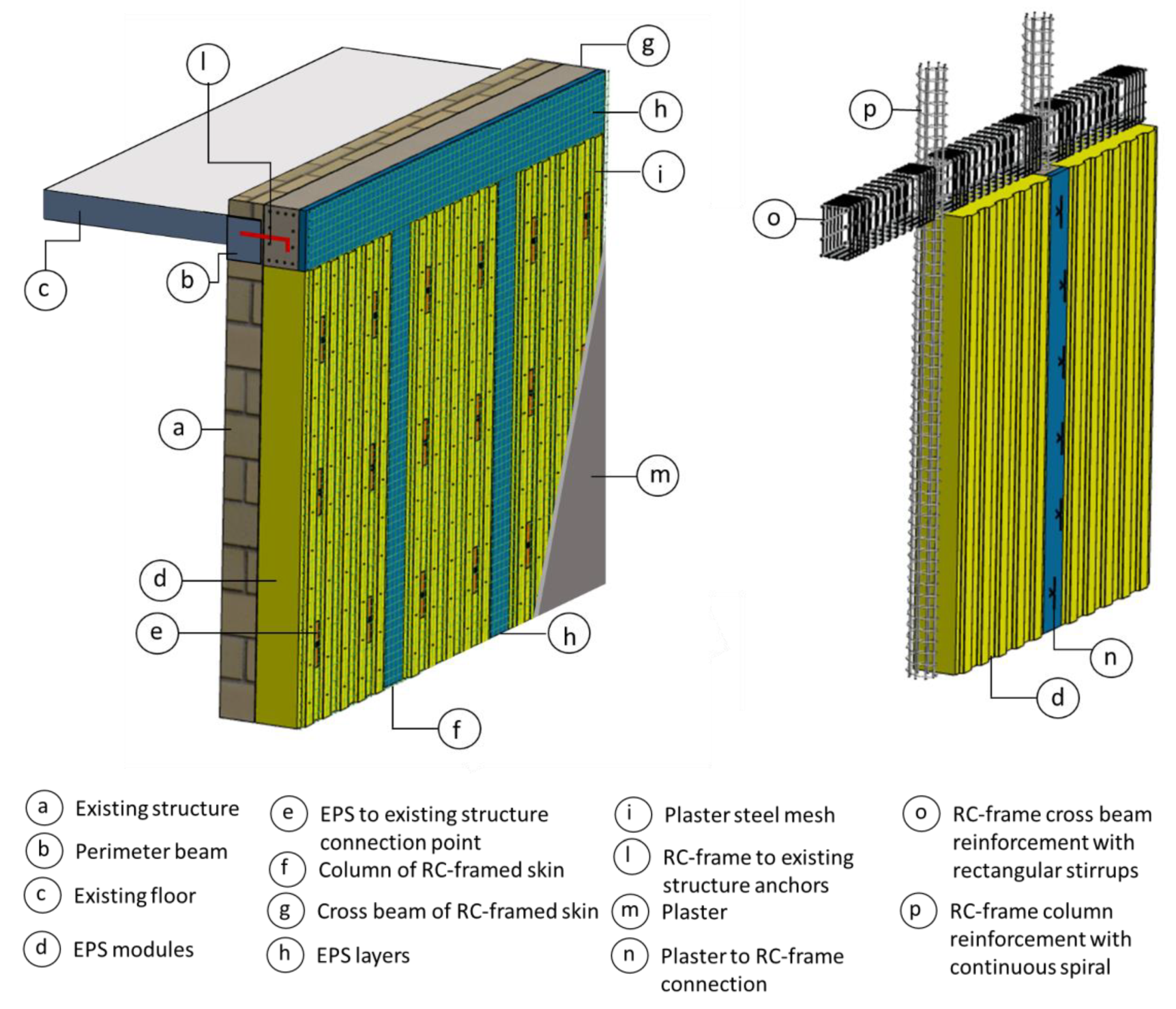
The proposed refurbishment methodology aims to limit invasiveness and interruption of use of the building; therefore, the reinforcement system should preferably be applied to the external façade minimizing internal interventions. Hence, the proposed technology consists of adding a cast on site RC frame system to the outer walls by rigidly connecting the reinforcement RC structure at the floor levels of the building (
Figure 1). The proposed retrofitting method could be effectively used for every type of building (steel or RC-frame, masonry) even if it turns out to be more suitable for RC-frame. The RC-framed skin is casted on site using prefabricated EPS modules which realize the formwork system and at the same time, ensure the thermal refurbishment of the building. The geometry of EPS modules is specifically shaped to realize, on the external surface, a thick and impact-resistant finishing plaster. The external plaster is reinforced with a steel mesh pre-assembled on the EPS modules and connected to the reinforcement RC frame by means of anchor rods.
The external reinforcement RC frame system is specifically designed to compensate the lack of seismic capacity of the existing building and is characterized by a modular geometry. The cross-section of the frame elements, the column interspace, and the reinforcement can be designed to achieve a specific target of seismic safety level.
Columns have a square cross-section with variable side dimensions in the range 150–300 mm. Transversal beams have a rectangular cross-section with base equal to the side of the column plus 50 mm and variable height dimension in the range 300–500 mm. The beam is positioned in contact with the existing structure in order to maximize the effectiveness of the connection system. The difference in thickness between the column and the beam is compensated with a special layer of EPS necessary to limit the linear thermal bridge at the inter-floor level.
Typical column interspace is equal to 1200 mm even if some adjustment can be required to fit the façade opening geometry.
Columns are characterized by continuous spiral transversal reinforcement while cross beams have common stirrups. In order to ensure adequate confinement of the beam-column joint, the spiral reinforcement of the column is continuous across the joint itself.
2.3. In Situ Installation Phases
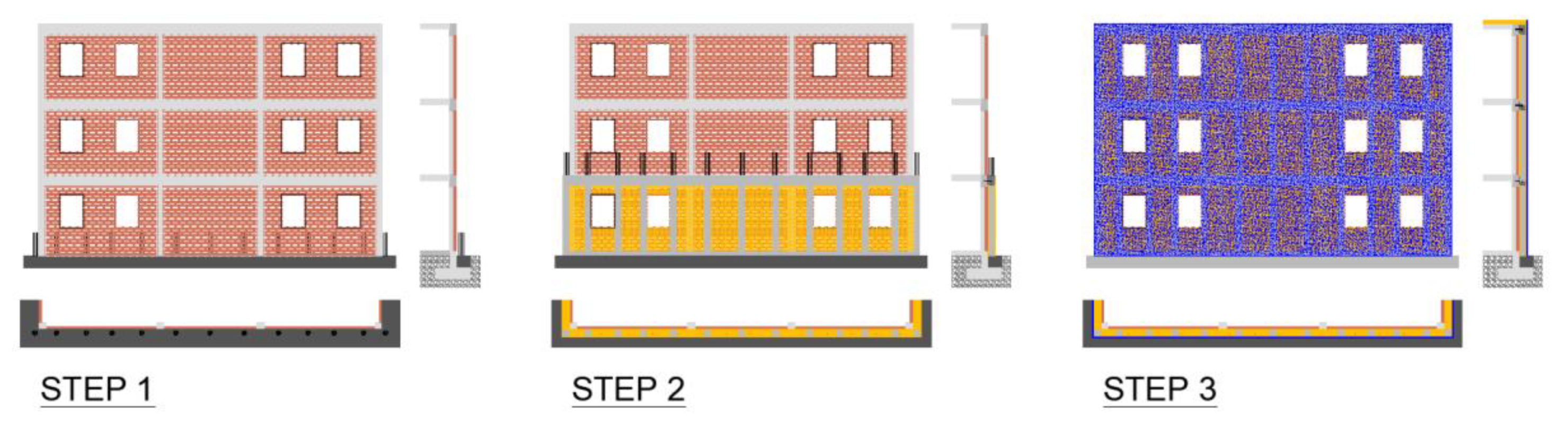
The main feature of the proposed reinforcement system is the possibility of installation from the outside of the building without internal intervention, thus limiting invasiveness and interruption of use. The installation of the RC-framed skin is platform type (i.e., floor by floor starting from the bottom) according to the following main steps schematically depicted in
Figure 2.
Step 1—Preparation of the façade and construction of the foundation beam. In this step, after a preliminary removal of the façade interfering installations (such as electrical, mechanical, or air conditioning systems), the excavation along the external perimeter of the building is carried out for the subsequent casting of the base curb. The base curb bears the weight of the new cladding system and is connected to the existing building by means of anchor rods. This connection makes the reinforcement structure integral with the existing foundation, avoiding sliding and uplift phenomena. The new foundation curb is reinforced continuously and is equipped with the reinforcement to be integrated in the subsequent casting of the reinforcing RC-frame column.
Step 2—Installation of the prefabricated EPS modules and casting of the reinforcement frame. In this step, the prefabricated EPS modules are fastened by means of non-structural mechanical anchors to the existing façade. The positioning of the EPS modules completely defines the structural grid of the reinforcing frame. Prior to the installation of the reinforcements inside the slots defined by the prefabricated module system, the structural anchor rods, necessary to connect the new RC frame to the existing structure, have to be fastened at floor level. Finally, the installation of the EPS layers in front of the columns and cross beam allows to complete the formwork for the subsequent casting of the structural concrete. The whole process described is repeated for each floor of the building.
Step 3—Realization of the external plaster and finishing of the façade. In this step the façade is completely plastered. The plaster is reinforced by the steel mesh integrated in the EPS modules and EPS covering layers and anchored to the EC-frame structure by means of mechanical connectors installed prior to the plastering phase. Refurbishment operations are completed with the accessory façade finishes (i.e., installation of the renovated doors and windows systems, upgrading of façade installations, etc.).
3. Multidisciplinary Performance Assessment of the RC-Framed Technology
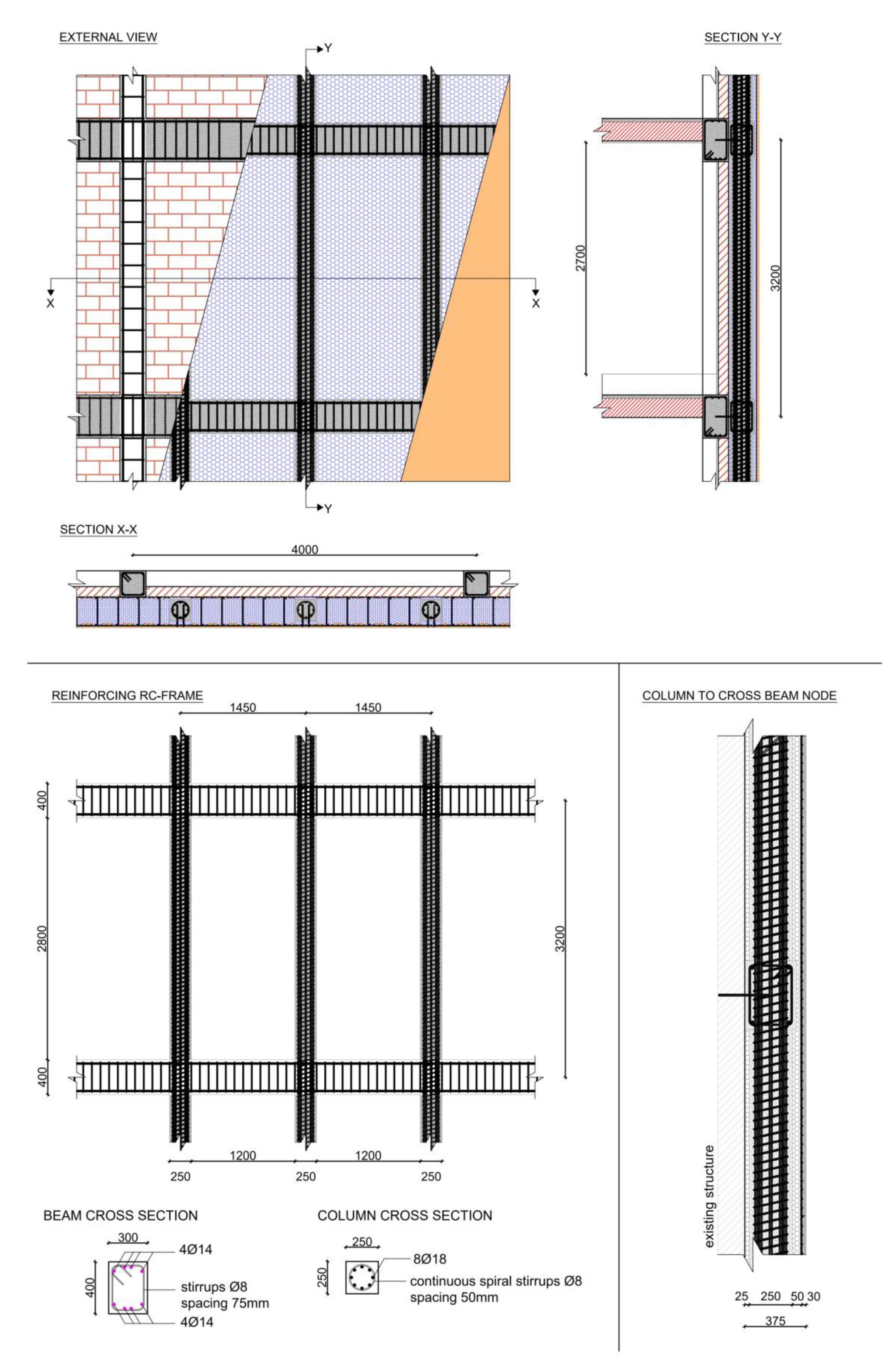
Multi-performance analyses of the proposed RC-framed skin technology was performed referring to a basic cell structure of a typical multi-story RC construction extracted from the existing Italian building stock. The basic cell structure is representative of the typical external span of an existing masonry infilled RC frame (
Figure 3a). The column spacing is 4000 mm while the inter-story height is 3200 mm. The columns have a 300 mm × 300 mm square cross-section while the beam has a 300 mm × 500 mm rectangular cross-section. The infill is a 125 mm thick brick masonry. External and internal surfaces were plastered with a 2 cm thick mortar plaster. Reinforcements of the existing frames were defined simulating the design practice adopted in Italy in the 1960s and 1970s, considering only vertical actions and disregarding the seismic horizontal forces [
1]. Then, both the beams and the columns are considered without any seismic detail: the spacing of the stirrups is very sparse without any spacing reduction at the end regions of the columns. Moreover, the stirrups of the column stop before the node. Geometry and reinforcement of the basic cell structure are detailed in
Figure 3b.
The proposed RC-framed skin was applied to the external surface of the basic cell structure and rigidly connected at the floor-level using anchor rods. Three EPS modules 1200 mm wide and 325 mm thick were used to clad the basic cell structure. Three 250 mm × 250 mm column were included in the reinforcement. The rectangular 300 mm × 400 mm cross beam was installed adherent to the existing structure and fixed at the floor level using 16 mm diameter anchor rods with spacing of 500 mm.
Geometry and reinforcement details of the RC-framed skin installed on the basic cell structure are reported in
Figure 4.
The assumptions and main results of seismic, thermo-hygrometric, acoustic, and LCA-LCC simulations of the unreinforced and reinforced basic cell structure are presented and discussed in the following sections.
3.1. Seismic Simulation
This section reports the results of seismic simulations carried out on the representative basic cell structure with the aim of investigating the structural response of the proposed RC-framed skin system. Specifically, a set of finite-element analyses was performed for both the unreinforced and reinforced configurations, also taking into account the effects due to the masonry infill on the existing frame. The models were implemented in OpenSees [
27] using the pre- and post- processor STKO [
28].
The material properties for concrete and reinforcement in both existing and RC-framed skin elements and of masonry infill are summarized in
Table 1. The mean compressive strength of concrete, assumed as C25 class for existing structure and C30 class for RC-framed skin, was evaluated according to Model Code 2010 [
29]. The mean yield strength, hardening ratio, and ultimate strain of the existing structure’s steel were selected by means of STIL software [
30,
31], where the probability distributions for those quantities are given based on an extensive database of experimental tests on reinforcing bars collected from samples of the second half of the last century, while the same properties for RC-framed skin’s steel (assumed as a reinforcing steel of class B450C) was taken from available experimental results [
32]. A Kent–Scott–Park constitutive model [
33,
34] with no tensile strength was selected for concrete, while an elastic-plastic law with strain hardening was selected for reinforcement.
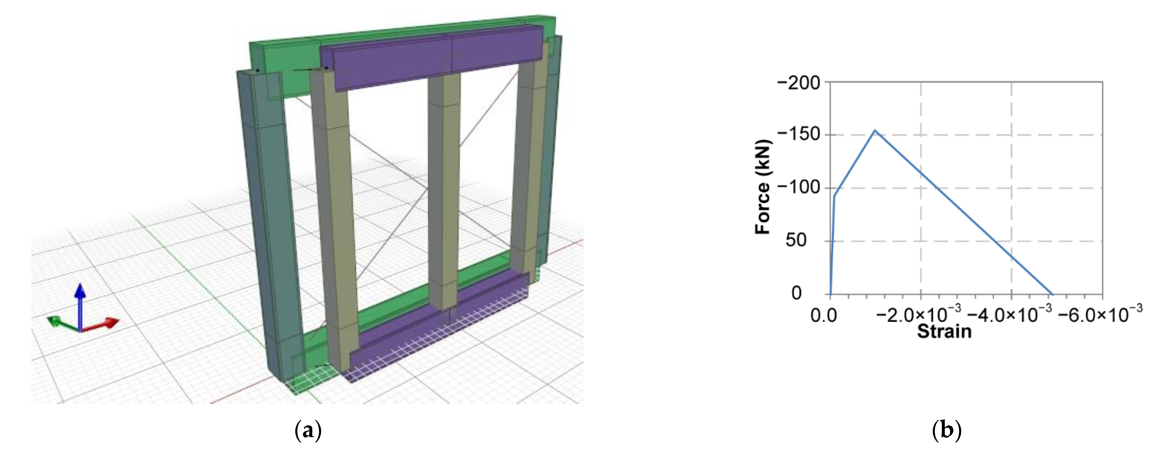
From the numerical point of view, the frame model, schematically depicted in
Figure 5a, was created using a lumped plasticity approach with finite length of plastic hinges, adopting in particular force beam-column elements with a modified two-point Gauss–Radau integration over each hinge region [
35], which ensures that localized deformations are integrated over the specified plastic hinge length. Plastic hinge length is computed according to the following relation [
36]:
where
is the shear span that was assumed equal to half the length of the element,
is the depth of the cross-section,
is the mean diameter of tensile reinforcement,
is yield strength of reinforcement, and
is compressive strength of concrete. Both
and
need to be in MPa. The computed values of plastic hinge length for both existing and RC-framed skin elements are 577 mm (existing beam), 493 mm (existing column), 459 mm (RC-framed skin beam), and 545 mm (RC-framed skin column). Moreover, ductile mechanisms and brittle mechanisms (i.e., shear) capacities were evaluated for all elements according to EN1998-3 [
36].
The effect of masonry infill was represented by means of an equivalent strut approach, according to ref. [
37]. In particular, two diagonal truss elements resisting only in compression were used with multilinear constitutive law whose parameters were computed taking into account the properties of the masonry infill. In these analyses, also due to their comparative nature, the infill was considered without openings for the sake of simplicity. The obtained constitutive law is depicted in
Figure 5b and is characterized by the following parameters: cracking force equal to 82.9 kN, maximum force equal to 138.2 kN, crack strain equal to
, maximum strain equal to
, and ultimate strain equal to
.
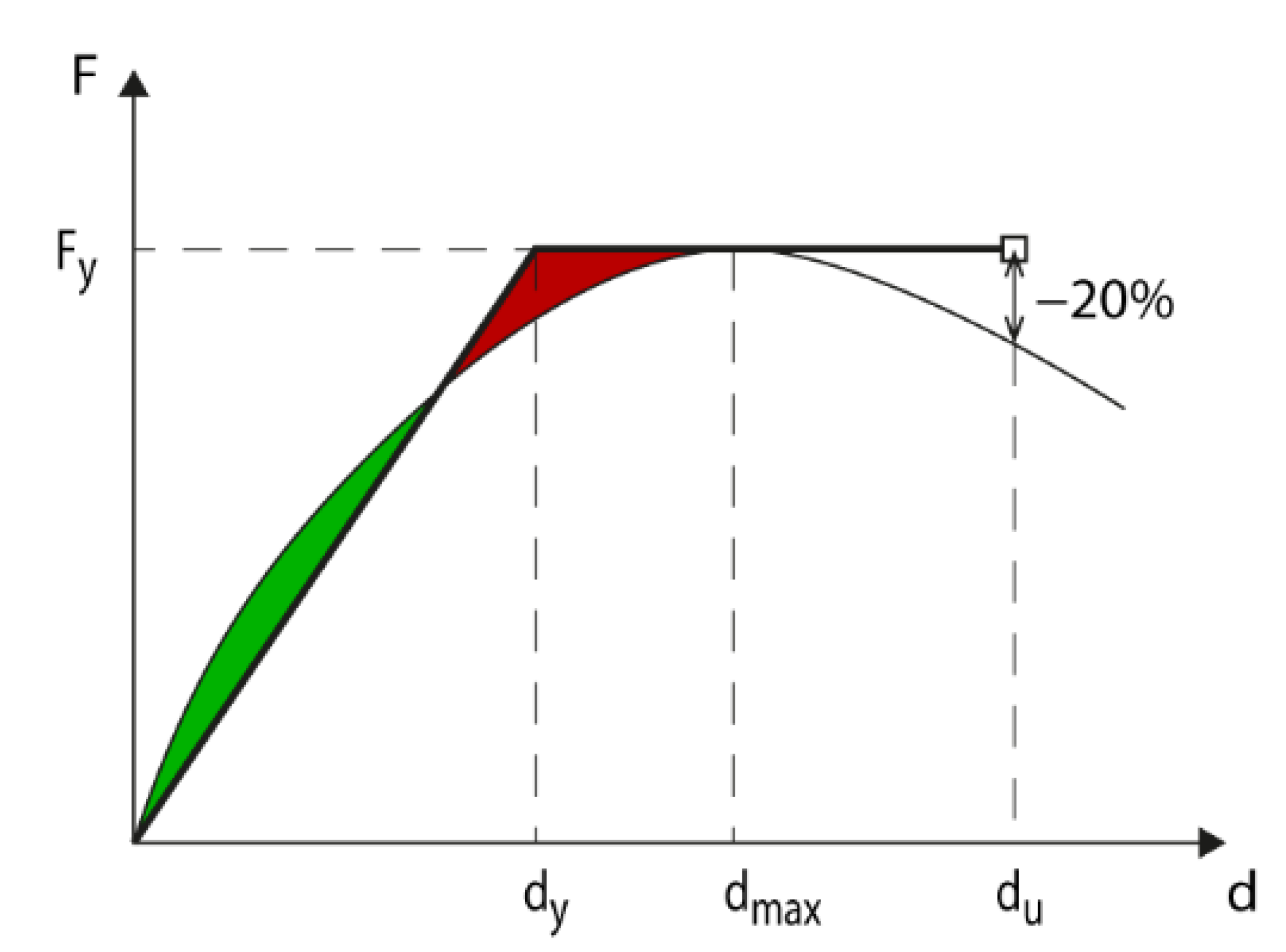
The typical loads of an intermediate level of a four-story building were considered in the analysis. More in detail, a load of 25 kN/m was applied to the beams of the existing frame, while the internal actions (shear, bending moment, and axial forces) deriving from the contiguous elements have been applied to the external nodes of the frame. The base nodes of the frame were restrained for displacement and rotation in all degrees of freedom. The reinforcing RC-framed skin was modeled as connected to the existing structure by means of kinematic constraints imposing the equality of the horizontal displacement. After the application of the vertical loads, an incremental horizontal load at the top of the frame was applied in order to compare the structural performance of the system by means of push-over curves. The push-over curves were then bilinearized according to
Figure 6, assuming the peak force as the yield force and the ultimate displacement as the first condition met between a drop of more than 20% of peak force or the attainment of a failure condition for at least one structural element (checked comparing the capacity of both ductile and brittle failure modes with the demand at each step of the analysis); finally, the yield displacement was computed evaluating the secant stiffness
Ksec through an energy balance between the idealized bilinear curve and the actual pushover curve.
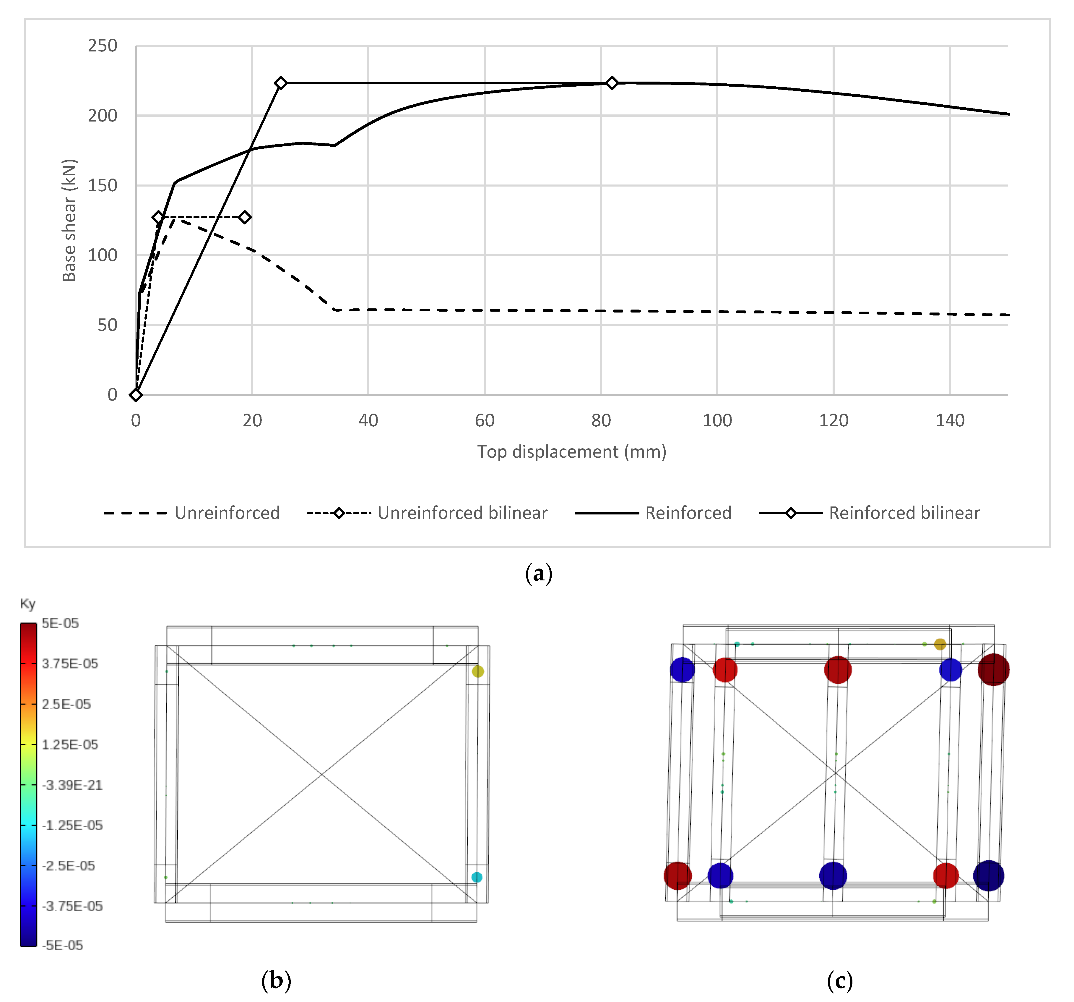
The results obtained for the bare frame in both reinforced and unreinforced configurations are depicted in
Figure 7a, where the pushover curves and the idealized bilinear curves are superimposed. The results in terms of stiffness, yield force, and ultimate force computed from the bilinear idealized curve are summarized in
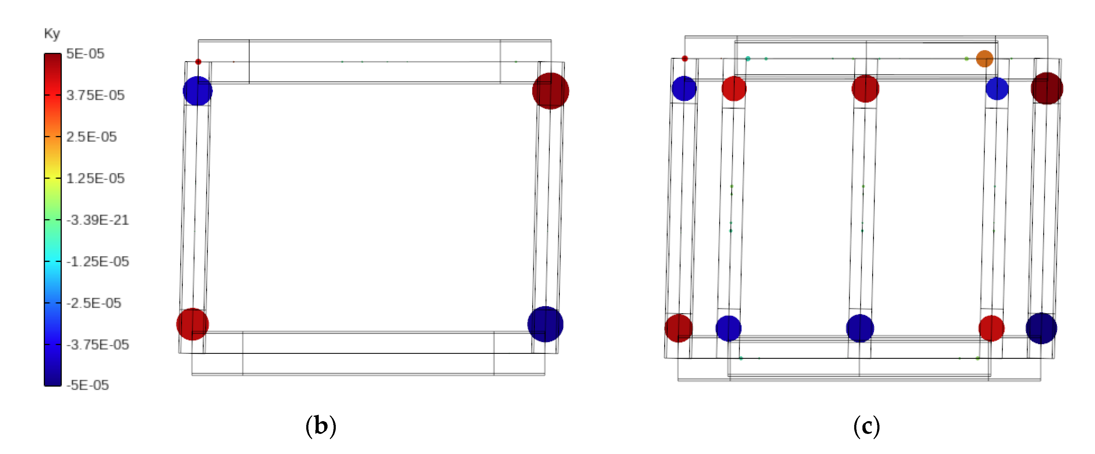
Table 2. It is possible to observe that the stiffness increased by a factor of 2, while the strength increased significantly by more than three times; finally, the ultimate displacement is not modified because it corresponds to the attainment of ultimate chord rotation capacity of a column of the existing frame. Concerning the failure mode, in the unreinforced configuration, a weak-column flexural mechanism was observed with formation of plastic hinges in top and bottom sections, as can be seen in
Figure 7b, where the curvature is depicted with colored circles indicating the localization of deformations. As for the failure mode for reinforced configuration, a weak column mechanism was observed for all columns of existing and RC-framed skin columns: top and bottom sections of existing and RC-framed skin columns almost simultaneously reached the yielding condition, see
Figure 7c.
The results obtained for the infilled frame in both reinforced and unreinforced configurations are depicted in
Figure 8a, where the pushover curves and the idealized bilinear curves are superimposed, while the results in terms of stiffness, yield force, and ultimate force computed from the bilinear idealized curve are summarized in
Table 2.
It is possible to observe that the yield force increases by about two times, while the ultimate displacement increases by around four times. Due to the bilinearization process, the stiffness of the reinforced configuration is apparently lower than the unreinforced configuration but inspecting the results closely, it is possible to see that the initial stiffness of the reinforced configuration is of course higher. The failure mode of the unreinforced configuration is due to the strength degradation of the masonry infill just after the formation of plastic hinges on the columns, as it is possible to see in
Figure 8b. For reinforced configuration, after the attainment of the maximum strength in masonry strut, the strength of the masonry strut continuously reduces, while at the same time, the new RC-framed skin structure adsorbs higher values of horizontal force. Thereafter, the plastic hinge formation on columns of existing and then of RC-framed skin takes place as reported in
Figure 8c.
3.2. Dynamic Thermo-Hygrometic and Acoustic Simulation
Thermo-hygrometric performances of the proposed retrofit system were evaluated implementing a bidimensional finite element model of the basic cell structure in the unreinforced and reinforced configuration, and computing both the heat fluxes and isothermal lines. The thermal transmittance U (W/m2K) was calculated as the ratio of the total heat flux to the area and the difference of temperature between internal and external environments. Temperature and heat transfer resistances used for U calculation were 20 °C and 0.13 m2K/W for the internal environment and 0 (°C) and 0.04 (m2K/W) for the external environment, respectively.
Table 3 compares thermal transmittance values
U and minimum internal temperature
Tmin of the reference basic cell structure of both unreinforced and reinforced configuration.
The reinforced configuration is characterized by U values significantly lower than the unreinforced configuration, ensuring high thermal performance of the building envelope.
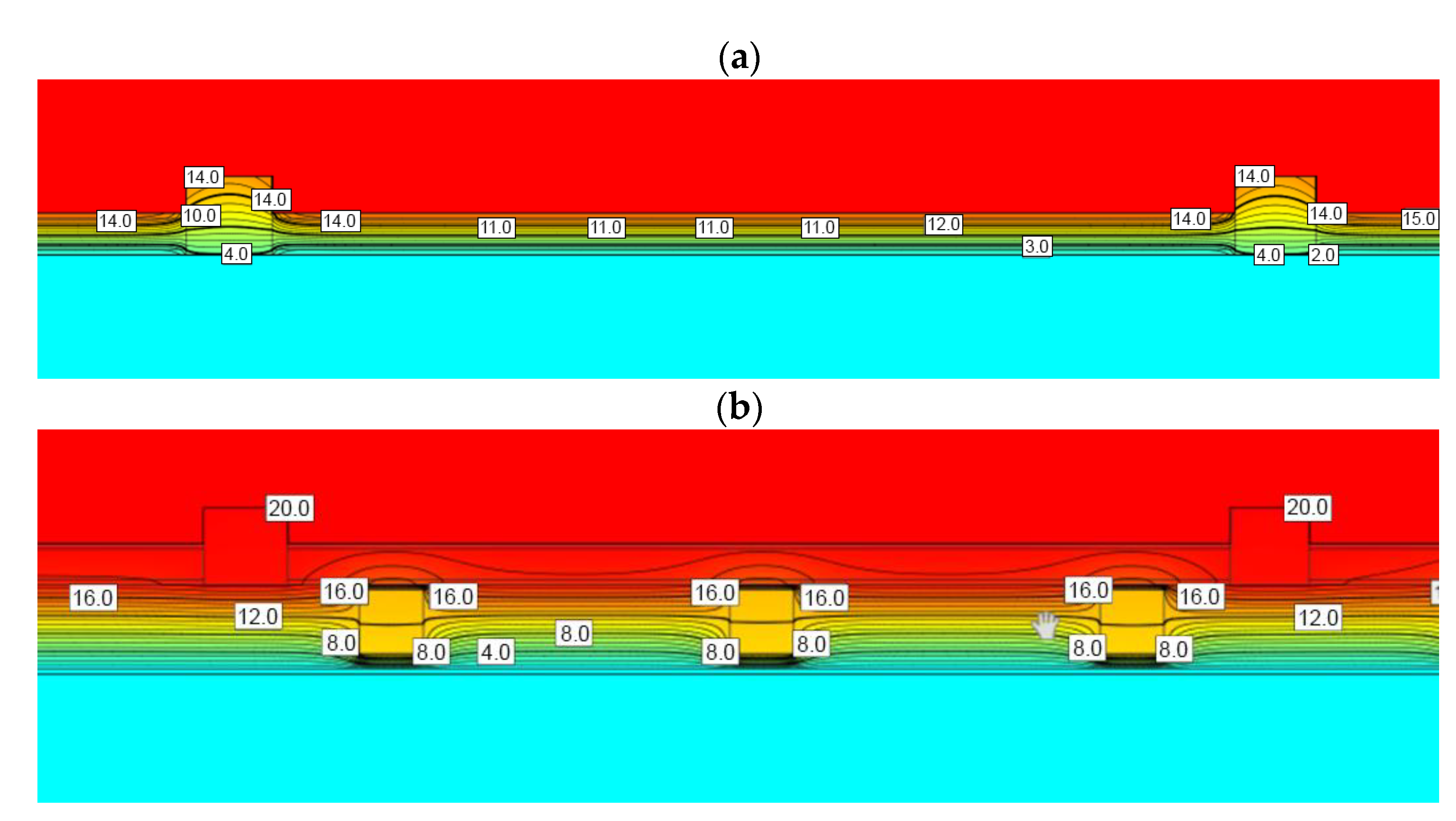
Figure 9 displays the isothermal lines obtained along the middle horizontal cross-section of the investigated basic cell structure in the unreinforced and reinforced configuration.
Analyzing the isothermal lines reported in
Figure 9, it is possible to observe that:
- -
The unreinforced configuration is characterized by a linear thermal bridge along the RC column which induces the risk of surface condensation due to the lowest values of internal surface temperature (about 11.5 °C). In addition to surface condensation risk, lower surface temperature causes discomfort inside the building for the lower radiant temperature.
- -
The reinforced configuration shows a minimum internal surface temperature greater than 19 °C avoiding the condensation risk and ensuring high thermal performance of the building envelope and high internal thermal comfort.
The modification of the acoustic insulation of the basic cell structure induced by the proposed RC-framed skin was investigated using the “Insul software” [
38]. Analyses were performed according to the procedure recommended by the ISO 12354-1 [
39] for both the unreinforced and reinforced configuration. It is worth nothing that the sound reduction index
R of a multilayer cladded element is strongly affected by the acoustic property of the basic structure and by the connection system [
40,
41].
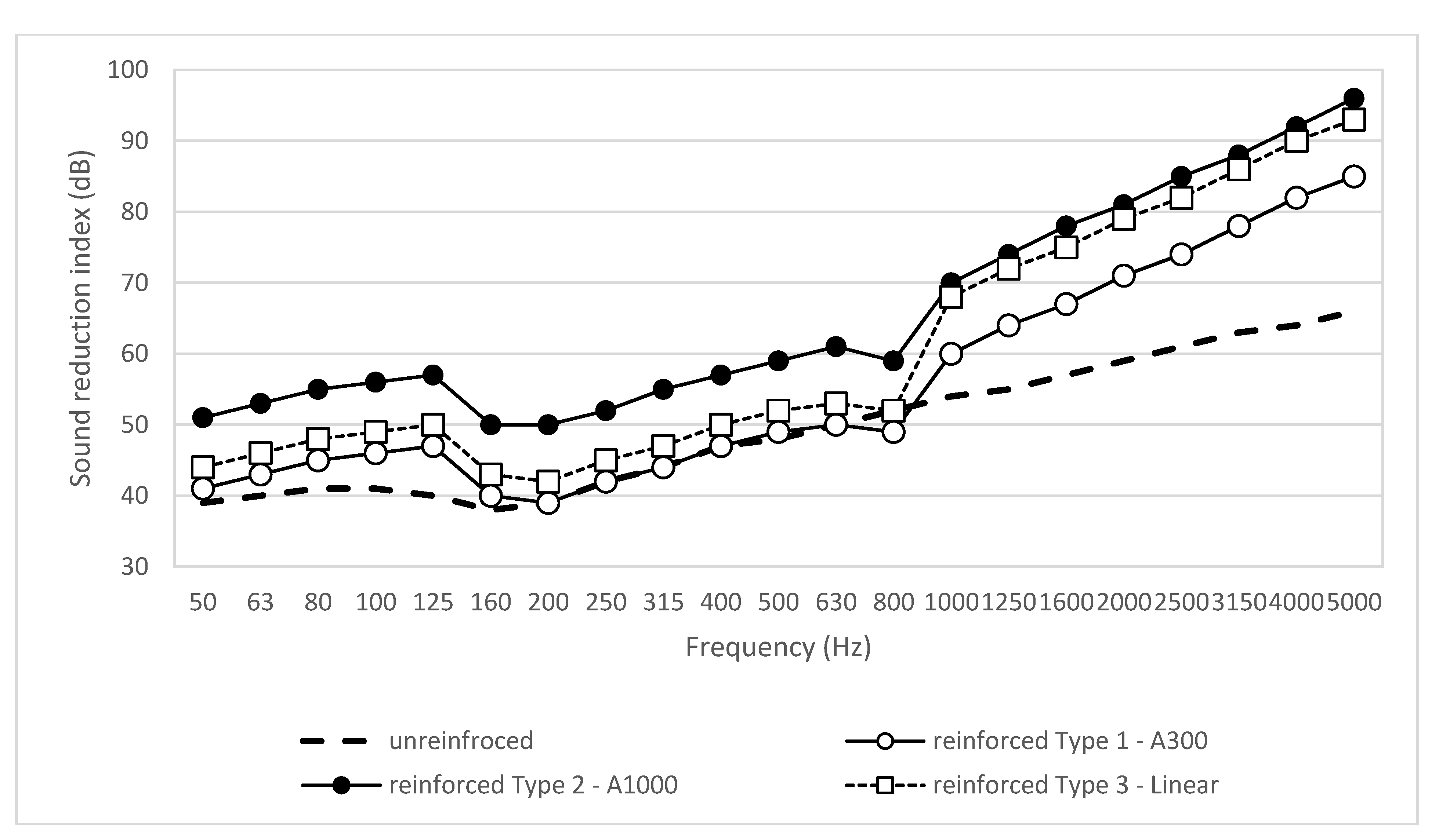
The first coincidence frequency of the basic cell structure is around 200 Hz and for the proposed RC-framed skin around 800 Hz. Then, three different types of connection used to fasten the RC-framed skin to the existing structure were investigated: Type 1-A300 punctual mechanical anchors with center-to-center distance of 300; Type 2-A1000 punctual mechanical anchors with center-to-center distance of 1000 mm; and Type 3-Linear linear connection (beam type). In
Figure 10, the effects of coincidence phenomena are shown at 200 Hz for basic cell and 800 Hz for RC-frame.
Regardless of the type of connection used, generally the RC-framed skin ensures an improvement of the sound reduction index R of the basic cell structure, except at the coincidence frequency of 800 Hz. The difference between Type 1-A300 and Type 2-A1000 is due to fewer connections.
For Type 1-A300 below 200 Hz, the improvement of R is due to the increase of mass for area. Between 200 Hz and 800 Hz, the behavior of the basic cell structure prevails, and it is mechanically coupled with RC-framed skin.
If Type 3-Linear connections are used, below 800 Hz, the results are quite similar to Type 1 (mechanically coupled with RC-framed skin), up to 800 Hz the RC-framed skin behaves like a plate rigidly constrained to the edges and the effect of decoupled layers prevails as in Type 2.
Results from acoustic analyses are summarized in
Table 4 in terms of the weighted sound reduction index
Rw (ISO 717-1) [
42] obtained for the two different investigated configurations. Results confirms that the application of the external RC-framed skin leads to an improvement in the sound reduction index
Rw of the basic cell structure regardless of the adopted connection system.
3.3. LCA and LCC Simulation
This section reports the evaluation of the environmental and economic impacts related to the construction phase of the proposed RC-framed technology.
In accordance with ISO 14040:2006 standard [
43], the Life Cycle Assessment (LCA) methodology and the impact assessment baseline IPCC 2013 were applied. The LCA is a standardized method, widely used to investigate the potential environmental impacts of a process, production systems, services, etc. It consists of an iterative process articulated in the following four phases: (i) goal and scope definition, (ii) inventory analysis, (iii) impact assessment, and (iv) results and interpretation.
Economic impacts were assessed by applying the Life Cycle Costing (LCC) methodology (ISO 15686-5:2017) [
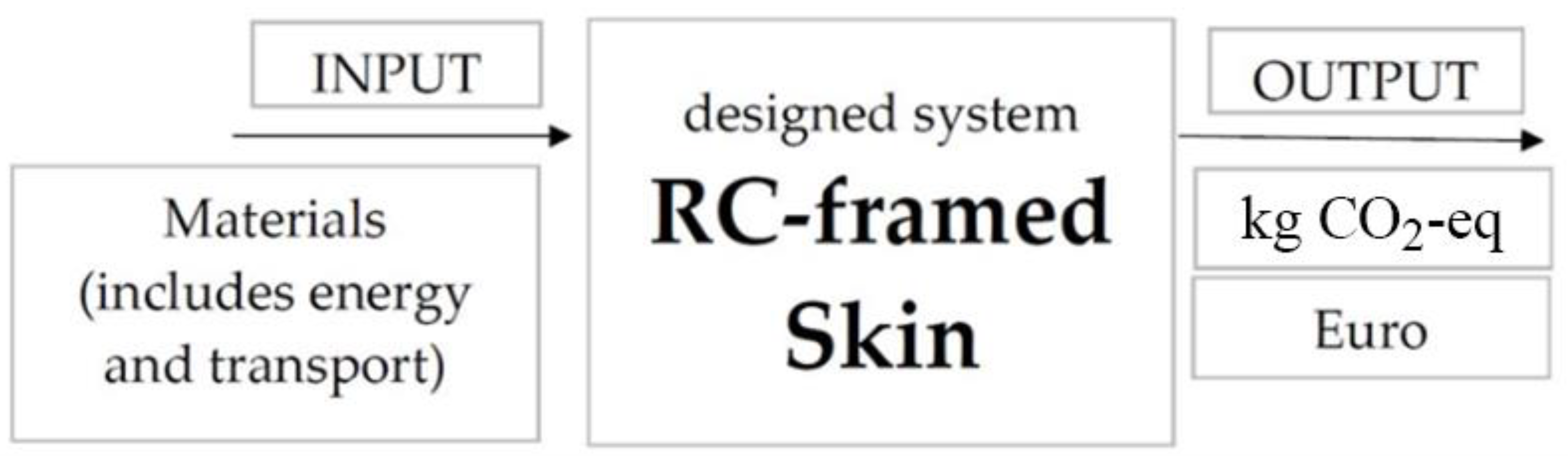
44]. LCC can be considered a useful complement to LCA: it covers a defined list of costs over the physical, technical, economic, or functional life of a constructed asset. For this purpose, the cost calculation associated with the construction phase of the designed technology was assessed.
In this context, an environmental assessment and a cost assessment of the designed technology were carried out. It is worth noting that functional unit and system boundaries set by the designed system were in common to environmental and economic analyses. As a functional unit, the RC-framed skin with a width of 4 m, a height of 3.2 m (12.8 m
2), and a weight of 3.7 tons was chosen, while the boundary conditions were from cradle to gate. The system object of the analysis included consumption of raw materials, energy, transport, and labor. It should be noted that the maintaining, operating, and end-of-life of the proposed RC-framed technology were out of system boundaries. According to the method proposed in the study conducted by Giresini et al. (2020) [
45], the aim of this analysis is to limit the CO
2-eq emissions that are normally produced considering retrofitting interventions. More specifically, only CO
2-eq emissions related to the phase of production and transport of the materials for the selected retrofitting intervention were considered (
Figure 11).
The LCA was chosen to evaluate the environmental impacts that affect the designed RC-framed technology (i.e., production and transportation of the involved materials) in compliance with the ISO 14040 standard [
43]. The Life Cycle Impact Assessment (LCIA) included the following mandatory elements: (i) the selection of impact categories and characterization models; (ii) the assignment of LCI results to the selected impact categories (classification); and (iii) the calculation of category indicator results (characterization).
The source of secondary data related to the environmental impacts of transportation and energy was the “Ecoinvent 3.5” database. The potential environmental impacts were evaluated using the software SimaPro
® 8 [
46]. The amount of CO
2-eq imputable to the designed technology was calculated. The climate change factors of the IPCC method were evaluated with a timeframe of 100 years (Global Warming Potential 100 in version 1.03). It should be noted that use and end-of-life phases were omitted due to the lack of primary data. Future research studies might evaluate the use and end-of-life phases in a cradle-to-grave approach, that will be quantifiable through existing sources.
The overall environmental impacts related to the construction phase of the RC-framed technology are shown in
Table 5.
Interestingly, structural steel and expanded EPS turned out to be the most impacting materials. As the total environmental impacts related to the selected functional unit was 2 tons of CO
2-eq, to obtain CO
2-eq/m
2, the result was divided by the considered surface equal to 12.8 m
2. As the average value is 156 kg of CO
2-eq/m
2 for a cradle-to-gate approach, the result appears to be a realistic assumption if compared to the study conducted by Eaton and Amato (1998) [
47], which assessed a pioneering study of the embodied CO
2-eq of steel, composite, reinforced, and precast concrete buildings. More specifically, the results of the above-mentioned study for the structure varied between 200 and 350 kgCO
2-eq/m
2.
Future research studies might evaluate the use and end-of-life phases in a cradle-to-grave approach, that will be quantifiable through existing sources.
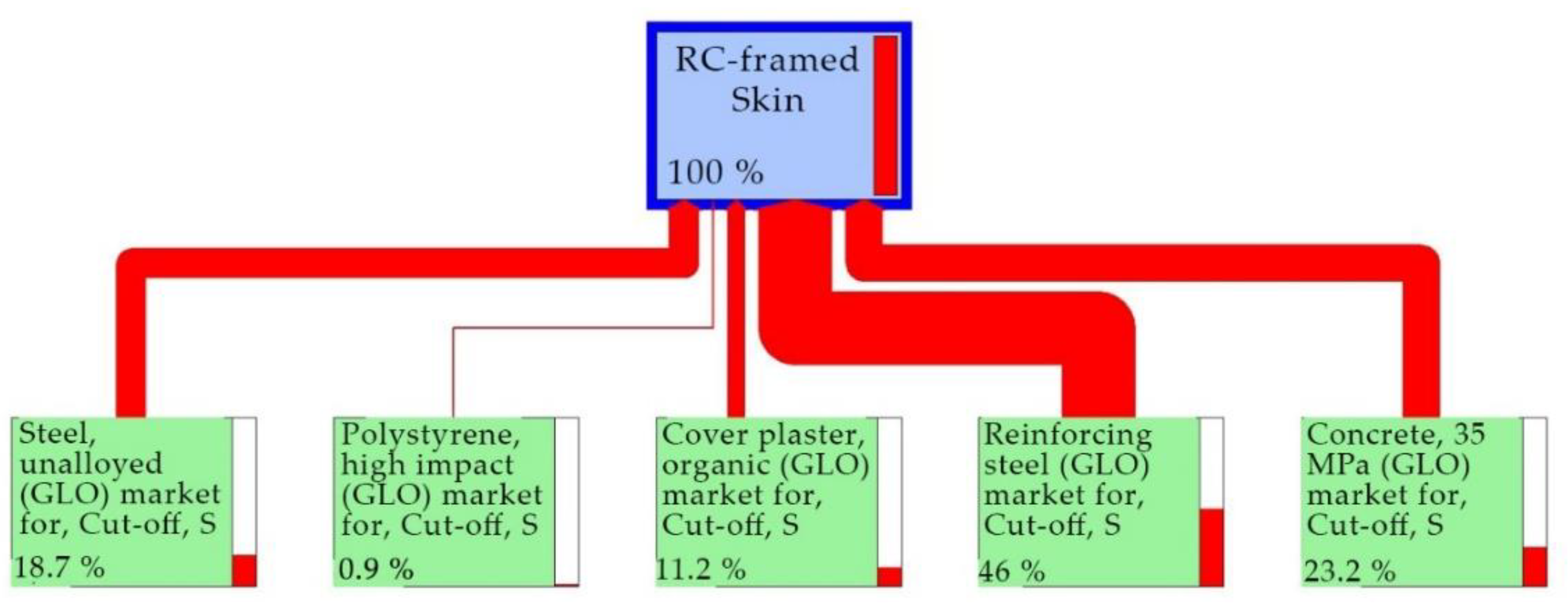
Finally, to better understand the results of the analysis,
Figure 12 shows the conceptual model elaborated by the software.
The tree model represents the designed system and indicates the negative environmental impacts with red lines whose size are proportional to the total amount of CO2-eq. Then, the results of LCA are used in the following section to measure the economic impact of the construction phase while future work will investigate the use and end-use phases.
The LCC analysis allowed the evaluation of the economic impacts that affect the designed RC-framed technology (i.e., raw materials, labor, and CO
2-eq externality). Generally, it can be necessary to include the external cost related to the impact of environmental externalities in the LCC analysis. In this context, the negative effects of the total amount of CO
2-eq (see
Table 5) imputable to the designed technology were evaluated. According to the European Union (EU) Emissions Trading System (ETS) [
48], the EU ETS carbon market price is currently around 44.06 euros per one ton of the CO
2-eq. Hence, the CO
2-eq externality is mathematically calculated multiplying the ETS carbon market price by the total carbon footprint value. Based on the previous materials (i.e., reinforced concrete, structural steel, expanded polystyrene (EPS), fiber-reinforced mortar, non-structural steel), the cost items were evaluated. The overall economic impacts related to the designed RC-framed technology are shown in
Table 6.
4. Discussion and Conclusions
The integrated reinforcement system presented in this paper, based on a RC-framed skin, is a promising renovation solution for existing buildings in terms of technical feasibility, seismic retrofit, energy efficiency, and architectural enhancement potential.
The proposed solution consists of cladding the building envelope with an innovative tailorable skin based on prefabricated EPS modules, which improve the energy and seismic performance as well as the architectural quality of the renovated buildings. The use of prefabricated EPS modules allows reducing implementation costs and time, embodied energy, and occupants’ disruption, resulting in a sustainable system from a social, economic, and environmental point of view.
The main strength of the proposed system consists in the possibility of carrying out the intervention from the outside of the building, thus limiting the impact on the use of the building itself by the inhabitants.
The multiperformance analysis, conducted on a selected basic cell structure, demonstrated an excellent seismic retrofit capacity, a significant improvement in the thermo-hygrometric behavior of the building, a reasonable acoustic improvement, and an environmental impact compatible with regulatory requirements.
Regarding the seismic issues, a set of push-over analyses were carried out on both unreinforced and reinforced configurations, also considering the effect of unreinforced masonry infills by means of an equivalent truss approach. The results show that in the case of bare frame (where the infill can be considered as not structurally efficient), the RC-framed skin reinforcement significantly increases the maximum shear capacity of the structure by more than three times. In the case of infilled frame, the reinforcing RC-framed skin leads to an increase of shear force by a factor of about two, while the ultimate displacement is significantly increased by a factor higher than four. Performed analysis demonstrated the positive effect of the proposed system on the structural behavior of the reinforced structure.
From the thermo-hygrometric point of view, the reinforcement allows a significant increase in transmittance and the substantial elimination of the thermal bridges of the existing structure, thus eliminating the risk of condensation and improving the quality of the internal environment.
The massiveness of the RC-framed skin also allows for an acoustic improvement of the existing structure even if results from analyses demonstrate that the weighted sound reduction index is strongly affected by the fastening system used to connect the reinforcement to the existing building.
LCA and LCC analyses were conducted to evaluate the consumption of raw materials, energy, transport, and labor for the realization phase of the system. It is worth nothing that, in this study, only CO2-eq emissions related to production and construction phases (from cradle to gate) were considered. The proposed solution has the ambition to contribute to sustainability and footprint reduction. Results, expressed in terms of carbon dioxide equivalent (CO2-eq) emissions, showed that environmental and economic impacts of the proposed technology are similar to other common RC-based retrofitting interventions, mainly in terms of the materials’ impact (reinforced concrete and structural steel, and expanded polystyrene). Although the environmental and cost analysis can be extended to the entire life of the building, this paper neglects that aspect, which will be considered in a future research study.
In conclusion, results from multidisciplinary performance assessment demonstrate that RC-framed skin is a promising technology for existing building refurbishment, and is capable of integrating inhabitants’ and the environment’s needs, in the perspective of making the building reuse scenario more attractive after retrofitting, as opposed to demolition and rebuild, thus reducing the demand for new green areas.
Finally, authors would like to point out that this research is only the preliminary stage of a more comprehensive research project; experimental investigations are currently ongoing to optimize the structural efficiency and limit the heat transfer through the thermal bridges, as well as the environmental impact.
Author Contributions
L.P.: conceptualization, methodology, validation, formal analysis, data curation, and writing—original draft preparation. A.D.E.: conceptualization, methodology, validation, formal analysis, data curation, and writing—original draft preparation. A.B.: conceptualization, validation, and supervision. D.T.: conceptualization, methodology, validation, formal analysis, data curation, and writing—original draft preparation. L.B.: formal analysis, data curation, and writing—original draft preparation. G.S.: formal analysis, data curation, and writing—original draft preparation. M.S.: supervision, project administration, funding acquisition, and writing—review and editing. All authors have read and agreed to the published version of the manuscript.
Funding
This research was funded by Regione Emilia Romagna POR-FESR 2014/2020-Asse 1.2.2–project TIMESAFE-Tecnologie integrate ed innovative a limitato impatto ed invasività per il miglioramento sismico degli edifici senza interruzione d’uso”-CUP J44I18000070007-PG/2018/631222_16/10/2018.
Institutional Review Board Statement
Not applicable.
Informed Consent Statement
Not applicable.
Data Availability Statement
Not applicable.
Acknowledgments
The authors would like to thank the partner company NTC&R (available online:
www.ntcer.it (accessed on 1 September 2020)) for the support and Claudio Azzolini for the kind cooperation.
Conflicts of Interest
The authors declare no conflict of interest.
References
- Margani, G.; Evola, G.; Tardo, C.; Marino, E.M. Energy, Seismic, and Architectural Renovation of RC Framed Buildings with Prefabricated Timber Panels. Sustainability 2020, 12, 4845. [Google Scholar] [CrossRef]
- Sajn, N. Energy Efficiency of Buildings: A Nearly Zero-Energy Future. European Parliamentary Research Service; European Union, 2016. Available online: https://www.europarl.europa.eu/RegData/etudes/BRIE/2016/582022/EPRS_BRI(2016)582022_EN.pdf (accessed on 2 May 2021).
- Landolfo, R.; Cascini, L.; Portioli, F. Sustainability of steel structures: Towards an integrated approach to life-time engineering design. Front. Archit. Civ. Eng. China 2011, 5, 304–314. [Google Scholar] [CrossRef] [Green Version]
- Eurostat. Energy Consumption in Households. Available online: https://ec.europa.eu/eurostat/statistics-explained/index.php?title=Energy_consumption_in_households#Energyproducts_used_in_the_residential_sector (accessed on 2 May 2021).
- BPIE (Buildings Performance Institute Europe). Available online: http://bpie.eu/wp-content/uploads/2017/12/State-of-the-building-stock-briefing_Dic6.pdf (accessed on 2 May 2021).
- Economidou, M.; Laustsen, J.; Ruyssevelt, P.; Staniaszek, D. Europe’s Buildings Under the Microscope; BPIE: Brussels, Belgium, 2011; ISBN 9789491143014. [Google Scholar]
- La Greca, P.; Margani, G. Seismic and Energy Renovation Measures for Sustainable Cities: A Critical Analysis of the Italian Scenario. Sustainability 2018, 10, 254. [Google Scholar] [CrossRef] [Green Version]
- Zanini, M.A.; Hofer, L.; Faleschini, F.; Toska, K.; Pellegrino, C. Seismic Risk Map for the Italian Residential Building Stock. In Proceedings of the 7th COMPDYN Conference, Crete, Greece, 24–26 June 2019; ISBN 978-618828445-6. [Google Scholar]
- Artola, I.; Rademaekers, K.; Williams, R.; Yearwood, J. Boosting Building Renovation: What Potential and Value for Europe; European Parliament: Brussels, Belgium, 2016. [Google Scholar]
- Seismic Hazard Harmonization in Europe (SHARE). European Seismic Hazard Map. 2013. Available online: http://www.share-eu.org/sites/default/files/SHARE_Brochure_public.web_.pdf (accessed on 2 May 2021).
- Belleri, A.; Marini, A. Does seismic risk affect the environmental impact of existing buildings? Energy Build. 2016, 110, 149–158. [Google Scholar] [CrossRef]
- Power, A. Housing and sustainability: Demolition or refurbishment? Proc. Inst. Civ. Eng. Urban Des. Plan. 2010, 163, 205–216. [Google Scholar] [CrossRef] [Green Version]
- Alshamrani, O.S.; Galal, K.; Alkass, S. Integrated LCA–LEED sustainability assessment model for structure and envelope systems of school buildings. Build. Environ. 2014, 80, 61–70. [Google Scholar] [CrossRef]
- Alba-Rodríguez, M.D.; Martínez-Rocamora, A.; Vallejo, P.G.; Sánchez, A.F.; Marrero, M. Building rehabilitation versus demolition and new construction: Economic and environmental assessment. Environ. Impact Assess. Rev. 2017, 66, 115–126. [Google Scholar] [CrossRef]
- Reid Middleton. Central Mexico Earthquake Reconnaissance. Available online: http://www.reidmiddleton.com/reidourblog/central-mexico-earthquake-reconnaissance-day-3/ (accessed on 2 May 2021).
- Pozza, L.; Marchi, L.; Trutalli, D.; Scotta, R. In-plane strengthening of masonry buildings with timber panels. Proc. Inst. Civ. Eng. Struct. Build. 2021, 50, 1734–1754. [Google Scholar] [CrossRef]
- Bournas, D.A. Concurrent seismic and energy retrofitting of RC and masonry building envelopes using inorganic textile-based composites combined with insulation materials: A new concept. Compos. Part B Eng. 2018, 148, 166–179. [Google Scholar] [CrossRef]
- Pertile, V.; De Stefani, L.; Scotta, R. Development and characterization of a system for the seismic and energy retrofit of existing buildings. Procedia Struct. Integr. 2018, 11, 347–354. [Google Scholar] [CrossRef]
- Trutalli, D.; Marchi, L.; Scotta, R.; Pozza, L. Seismic Capacity of Irregular Unreinforced Masonry Buildings with Timber Floors. Struct. Build. 2021, 174, 473–490. [Google Scholar] [CrossRef]
- Scotta, R.; Trutalli, D.; Marchi, L.; Pozza, L. Seismic performance of URM buildings with in-plane non-stiffened and stiffened timber floors. Eng. Struct. 2018, 167, 683–694. [Google Scholar] [CrossRef]
- Artino, A.; Evola, G.; Margani, G.; Marino, E.M. Seismic and Energy Retrofit of Apartment Buildings through Autoclaved Aerated Concrete (AAC) Blocks Infill Walls. Sustainability 2019, 11, 3939. [Google Scholar] [CrossRef] [Green Version]
- Ferrante, A.; Mochi, G.; Predari, G.; Badini, L.; Fotopoulou, A.; Gulli, R.; Semprini, G. A European Project for Safer and Energy Efficient Buildings: Pro-GET-onE (Proactive Synergy of inteGrated Efficient Technologies on Buildings’ Envelopes). Sustainability 2018, 10, 812. [Google Scholar] [CrossRef] [Green Version]
- D’Urso, S.; Cicero, B. From the Efficiency of Nature to Parametric Design. A Holistic Approach for Sustainable Building Renovation in Seismic Regions. Sustainability 2019, 11, 1227. [Google Scholar] [CrossRef] [Green Version]
- Marini, A.; Passoni, C.; Belleri, A.; Feroldi, F.; Preti, M.; Metelli, G.; Riva, P.; Giuriani, E.; Plizzari, G. Combining seismic retrofit with energy refurbishment for the sustainable renovation of RC buildings: A proof of concept. Eur. J. Environ. Civ. Eng. 2017, 21, 1–21. [Google Scholar] [CrossRef]
- Manfredi, V.; Masi, A. Seismic Strengthening and Energy Efficiency: Towards an Integrated Approach for the Rehabilitation of Existing RC Buildings. Buildings 2018, 8, 36. [Google Scholar] [CrossRef] [Green Version]
- Stazi, F.; Serpilli, M.; Maracchini, G.; Pavone, A. An experimental and numerical study on CLT panels used as infill shear walls for RC buildings retrofit. Constr. Build. Mater. 2019, 211, 605–616. [Google Scholar] [CrossRef]
- McKenna, F.; Scott, M.H.; Fenves, G.L. Nonlinear finite-elemen analysis software architecture using object composition. J. Comput. Civ. Eng. 2010, 24, 95–107. [Google Scholar] [CrossRef]
- Petracca, M.; Candeloro, F.; Camata, G. STKO User Manual; ASDEA Software Technology: Pescara, Italy, 2017. [Google Scholar]
- The International Federation for Structural Concrete (Fib). Fib Model Code for Concrete Structures 2010; Ernst & Sohn: Berlin, Germany, 2013. [Google Scholar] [CrossRef]
- Verderame, G.M.; Stella, A.; Cosenza, E. Le proprietà meccaniche degli acciai impiegati nelle strutture in c.a. realizzate negli anni ‘60. In Proceedings of the Atti del X congresso nazionale ANIDIS “L’ingegneria Sismica in Italia”, Potenza-Matera, Italy, 9–13 September 2001. (In Italian). [Google Scholar]
- Ricci, P. Seismic Vulnerability of Existing RC Buildings. Ph.D. Dissertation, Università degli Studi di Napoli Federico II, Napoli, Italy, 2010. [Google Scholar]
- Berto, L.; Caprili, S.; Saetta, A.; Salvatore, W.; Talledo, D. Corrosion effects on the seismic response of existing rc frames designed according to different building codes. Eng. Struct. 2020, 216, 110397. [Google Scholar] [CrossRef]
- Kent, D.C.; Park, R. Flexural members with confined concrete. J. Struct. Div. 1971, 97, 1969–1990. [Google Scholar] [CrossRef]
- Scott, B.D.; Park, R.; Priestley, M.J.N. Stress-strain behavior of concrete confined by overlapping hoops at low and high strain rates. ACI J. 1982, 79, 13–27. [Google Scholar]
- Scott, M.H.; Fenves, G.L. Plastic hinge integration methods for force-based beam-column elements. J. Struct. Eng. 2006, 132, 244–252. [Google Scholar] [CrossRef]
- EN1998-3. Eurocode 8: Design of Structures for Earthquake Resistance, Part 3: Assessment and Retrofitting of Buildings; European Committee for Standardization: Brussels, Belgium, 2004. [Google Scholar]
- Martinelli, E.; Lima, C.; De Stefano, G. A simplified procedure for Nonlinear Static analysis of Masonry Infilled RC frames. Eng. Struct. 2015, 101, 591–608. [Google Scholar] [CrossRef]
- Insul v.9. Developed by Marshall Day Acoustics; Auckland, New Zealand, 2021. [Google Scholar]
- ISO. 12354-1:2017 Building Acoustics—Estimation of Acoustic Performance of Buildings from the Performance of Elements—Part 1: Airborne Sound Insulation between Rooms; International Organization for Standardization, 2017. Available online: https://www.iso.org/standard/70242.html (accessed on 30 April 2021).
- Hopkins, C. Sound Insulation; Elsevier: Oxford, UK, 2007; ISBN 978-0-7-7506-6526-1. [Google Scholar]
- Beranek, L.; Ver, I. Noise and Vibration Control Engineering; John Wiley & Sons, Inc.: New York, NY, USA, 1992. [Google Scholar]
- ISO. 717-1:2013 Acoustics—Rating of Sound Insulation in Buildings and of Building Elements—Part 1: Airborne Sound Insulation; International Organization for Standardization, 2013. Available online: https://www.iso.org/standard/51968.html (accessed on 30 April 2021).
- ISO. 14040:2006. Environmental Management—Life Cycle Assessment—Part 1: Principles and Framework; International Organization for Standardization, 2006. Available online: https://www.iso.org/standard/37456.html (accessed on 30 April 2021).
- ISO. 15686-5:2017. Buildings and Constructed Assets—Service Life Planning—Part 5: Life-Cycle Costing; International Organization for Standardization, 2017. Available online: https://www.iso.org/standard/61148.html (accessed on 30 April 2021).
- Giresini, L.; Paone, S.; Sassu, M. Integrated Cost-Analysis Approach for Seismic and Thermal Improvement of Masonary Building Façades. Buildings 2020, 10, 143. [Google Scholar] [CrossRef]
- SimaPro®. Available online: https://simapro.com/ (accessed on 15 April 2021).
- Eaton, K.J.; Amato, A. A comparative life cycle assessment of steel and concrete framed office buildings. J. Constr. Steel Res. 1998, 46, 286–287. [Google Scholar] [CrossRef]
- EU European Union Emissions Trading System. 2021. Available online: https://ember-climate.org/data/carbon-price-viewer/ (accessed on 15 May 2021).
- Emilia, R. Camera di Commercio Industria Artigianato e Agricoltura di Reggio Emilia. Prezzi Informativi. Materiali da Costruzione ed Opere Edili. Libro LIV. Edizione 2020. Available online: http://www.re.camcom.gov.it/allegati/PREZZARIO%202020_210108115057.pdf (accessed on 15 May 2021).
Figure 1.
RC-framed skin: global view and detail of an EPS module and reinforcement.
Figure 1.
RC-framed skin: global view and detail of an EPS module and reinforcement.
Figure 2.
Scheme of the in situ installation phase.
Figure 2.
Scheme of the in situ installation phase.
Figure 3.
Basic cell structure: (a) global view and (b) geometrical details and elements reinforcement.
Figure 3.
Basic cell structure: (a) global view and (b) geometrical details and elements reinforcement.
Figure 4.
Geometry and reinforcement details of the RC-framed skin (basic cell structure).
Figure 4.
Geometry and reinforcement details of the RC-framed skin (basic cell structure).
Figure 5.
(a) FE Model for seismic analyses of a masonry infilled frame with reinforcing RC-framed skin; (b) constitutive law adopted for masonry infill equivalent trusses.
Figure 5.
(a) FE Model for seismic analyses of a masonry infilled frame with reinforcing RC-framed skin; (b) constitutive law adopted for masonry infill equivalent trusses.
Figure 6.
Bilinearization procedure for pushover curves.
Figure 6.
Bilinearization procedure for pushover curves.
Figure 7.
Bare frame case: (a) structural response of unreinforced and reinforced configuration; curvature (ky) in integration points at ultimate displacement for: (b) unreinforced configuration, (c) reinforced configuration.
Figure 7.
Bare frame case: (a) structural response of unreinforced and reinforced configuration; curvature (ky) in integration points at ultimate displacement for: (b) unreinforced configuration, (c) reinforced configuration.
Figure 8.
Infilled frame case: (a) structural response of unreinforced and reinforced configuration; curvature (ky) in integration points at ultimate displacement for: (b) unreinforced configuration, (c) reinforced configuration.
Figure 8.
Infilled frame case: (a) structural response of unreinforced and reinforced configuration; curvature (ky) in integration points at ultimate displacement for: (b) unreinforced configuration, (c) reinforced configuration.
Figure 9.
Isothermal lines from FEM analyses along the horizontal cross section of the basic cell structure for: (a) unreinforced and (b) reinforced configuration.
Figure 9.
Isothermal lines from FEM analyses along the horizontal cross section of the basic cell structure for: (a) unreinforced and (b) reinforced configuration.
Figure 10.
Sound reduction index R for unreinforced and reinforced configurations and for different connection types.
Figure 10.
Sound reduction index R for unreinforced and reinforced configurations and for different connection types.
Figure 11.
Diagram flow of the RC-framed skin.
Figure 11.
Diagram flow of the RC-framed skin.
Figure 12.
Tree model of the proposed RC-framed technology.
Figure 12.
Tree model of the proposed RC-framed technology.
Table 1.
Material properties.
Table 1.
Material properties.
| Material | Property | Value |
|---|
| Existing structure: Concrete | Compressive strength | 33 MPa |
| Strain at peak stress | 0.002 |
| Ultimate stress | 0 MPa |
| Ultimate strain | 0.006 |
| Existing structure: Steel | Yield strength | 524 MPa |
| | Hardening ratio 1 | 1.5 |
| | Ultimate strain | 22.5% |
| Existing structure: Masonry infill | Compressive strength | 5.0 MPa |
| | Shear strength (w/o axial load) | 0.2 MPa |
| | Young modulus | 2100 MPa |
| | Shear modulus | 875 MPa |
| RC-framed skin: Concrete | Compressive strength | 38 MPa |
| | Strain at peak stress | 0.002 |
| | Ultimate stress | 0 MPa |
| | Ultimate strain | 0.006 |
| RC-framed skin: Steel | Yield strength | 496 MPa |
| | Hardening ratio 1 | 1.21 |
| | Ultimate strain | 26.3% |
Table 2.
Summary of seismic simulations.
Table 2.
Summary of seismic simulations.
| Configuration | Ksec (kN/mm) | Fmax (kN) | Du (mm) |
|---|
| Unreinforced bare frame | 2.58 | 60.94 | 81.30 1 |
| Reinforced bare frame | 5.30 | 217.84 | 81.86 1 |
| Unreinforced infilled frame | 32.46 | 127.35 | 18.77 2 |
| Reinforced infill frame | 8.95 | 223.41 | 81.91 1 |
Table 3.
Thermal transmittance and minimum internal temperature values for the examined configurations.
Table 3.
Thermal transmittance and minimum internal temperature values for the examined configurations.
| Wall Type | U (W/m2K) | Tmin (°C) |
|---|
| Unreinforced configuration 1 | 1.86 | 11.5 |
| Reinforced configuration | 0.15 | 19.5 |
Table 4.
Weighted sound reduction index Rw for the unreinforced and reinforced systems.
Table 4.
Weighted sound reduction index Rw for the unreinforced and reinforced systems.
| Wall Type | Rw (dB) |
|---|
| Unreinforced configuration | 52 |
| Reinforced configuration | |
| Type 1-A300 | 53 |
| Type 2-A1000 | 63 |
| Type 3-Linear | 56 |
Table 5.
Environmental impacts related to the construction phase of the RC-framed technology.
Table 5.
Environmental impacts related to the construction phase of the RC-framed technology.
| Material | Process | Source | Carbon Footprint
(CO2-eq) |
|---|
| Reinforced concrete | Concrete, 35 MPa | Ecoinvent 3 allocation cut-off by classification | |
| Structural steel | Reinforcing steel | |
| Expanded polystyrene (EPS) | Polystyrene, high impact | |
| Fiber-reinforced mortar | Cover plaster, organic | |
| Non-structural steel | Unalloyed steel | |
| | | Total | |
Table 6.
Economic impacts related to the designed RC-framed technology.
Table 6.
Economic impacts related to the designed RC-framed technology.
| Cost Items | Source | Cost (Euro) |
|---|
| Reinforced concrete | Bologna, 2019 [43]
Reggio Emilia, 2020 [49] | 118 |
| Structural steel | 1618 |
| Expanded polystyrene (EPS) | 293 |
| Fiber-reinforced mortar | 138 |
| Non-structural steel | 191 |
| Labor | 909 |
| CO2-eq externality | EU, 2021 [48] | 88 |
| Publisher’s Note: MDPI stays neutral with regard to jurisdictional claims in published maps and institutional affiliations. |
© 2021 by the authors. Licensee MDPI, Basel, Switzerland. This article is an open access article distributed under the terms and conditions of the Creative Commons Attribution (CC BY) license (https://creativecommons.org/licenses/by/4.0/).


 ,
, 


