Article

Chinese High Rise Reinforced Concrete Building Retrofitted with CLT Panels

1
Department of Architecture, Roma Tre University, 00153 Rome, Italy
2
College of Civil Engineering, Fuzhou University, Fuzhou 350108, China
*
Author to whom correspondence should be addressed.
Sustainability 2021, 13(17), 9667; https://doi.org/10.3390/su13179667
Submission received: 1 July 2021 / Revised: 19 August 2021 / Accepted: 23 August 2021 / Published: 27 August 2021

Abstract

:
Cross laminated timber (CLT) panels have been gaining increasing attention in the construction field as a diaphragm in mid- to high-rise building projects. Moreover, in the last few years, due to their seismic performances, low environmental impact, ease of construction, etc., many research studies have been conducted about their use as infill walls in hybrid construction solutions. With more than a half of the megacities in the world located in seismic regions, there is an urgent need of new retrofitting methods that can improve the seismic behavior of the buildings, upgrading, at the same time, the architectural aspects while minimizing the environmental impact and costs associated with the common retrofit solutions. In this work, the seismic, energetic, and architectural rehabilitation of tall reinforced concrete (RC) buildings using CLT panels are investigated. An existing 110 m tall RC frame building located in Huizhou (China) was chosen as a case study. The first objective was to investigate the performances of the building through the non-linear static analysis (push-over analysis) used to define structural weaknesses with respect to earthquake actions. The architectural solution proposed for the building is the result of the combination between structural and architectonic needs: internal spaces and existing facades were re-designed in order to improve not only the seismic performances but also energy efficiency, quality of the air, natural lighting, etc. A full explanation of the FEM modeling of the cross laminated timber panels is reported in the following. Non-linear FEM models of connections and different wall configurations were validated through a comparison with available lab tests, and finally, a real application on the existing 3D building was discussed.

1. Introduction

In 2014, more than half of the world’s population lived in cities and it is expected that over 70% will be living in cities by 2050. In China, starting from 1978, with the enactment of the “Reform and Opening-up” policy, cities have grown over 10% per year, increasing the urbanization of the country from 17.4% to 46.8% in about three decades [1]. While well-planned urbanization can encourage economic growth, on the contrary, massive urbanization brings along with it multiple side effects concerning landscape and aesthetics values of the cities tied to the social, energetic, and environmental sphere. The environmental impact of cities in developing countries is a growing worry and it was often associated with over-concentration due to high-rise and high-density buildings development. Approximately half of the world’s megacities are located in seismic regions and their suburbs are often characterized by residential blocks with poor or missing energetic, seismic, and architectural design. As a result, there is an urgent need for appropriate retrofitting solutions for tall buildings that can withstand the large demands imposed by earthquakes, while minimizing the environmental costs associated with their installation and maintenance. In the last decade there was a growing interest in retrofitting solutions based on the use of engineering wood products (EWP), such as cross laminated timber (CLT), oriented strand board (OSB), laminated veneer lumber (LVL), etc. EWP were used both in form of planar elements, strong-backs (vertical timber elements), or timber straps to propose interventions solutions for URM [2,3,4,5,6,7,8,9,10,11,12], adobe masonry [13,14], stone masonry [15], and finally reinforced concrete structures [16]. Sustersic Dujic [17,18,19] proposed a seismic strengthening and energetic improvement solution for both RC and masonry buildings. CLT short or long panels addiction to RC frame structure by means of typical metal connections was first numerically investigated. Second, an ad hoc bracket was designed and used to jacket existing buildings from the outside by means of a steel plate attached to the main structure with steel threaded rods drilled into the structure and anchored with an epoxy resin. A series of experimental tests on an RC frame were finally performed on the shaking table. Haba et al. [20] tested a large number on a one-third-scale RC frames specimens with seven or four pairs of short CLT panels (2100 mm) infilled. These panels were three layer/three-ply Japanese cedar panels (30 mm thick) bounded by each other and to the RC frame with epoxy resin on-site. Every specimen showed an increase in terms of stiffness, strength, and ductility compared to the RC frame. Stazi et al. [21] first investigated CLT panels under diagonal compression using a testing procedure specially developed for masonry walls, and second, numerically analyzed changes in RC in lateral response of a one-story one-bay RC frame with CLT infill. In numerical analysis, both CLT infill and the RC frame were fixed at their bases, and a perfect bonding was assumed at the interfaces between the CLT panel and RC frame. The proposal by Smiroldo et al. [22] consisted of the replacement of existing masonry infill with CLT panels connected to the RC frame by means of a substructure in GlueLam and dissipative dowel-type fasteners. In certain cases, the intervention could be coupled with local strengthening of column-to-beam joints by means of FRP jacketing. The retrofitted frames showed an initial stiffness that was intermediate to that of the bare configurations and the masonry infilled ones, an overall ductile behavior, and an increase in maximum load bearing capacity. Margani et al. [23] demonstrated the improvement in terms of energetic performance of a multi-story apartment RC building associated with the addition of CLT panels to the original RC-framed structure with masonry infill. CLT panels were designed for the blind façade and applied through innovative seismic energy dissipation devices for this purpose design. Results showed a reduction in energetic consumption, and it ensured excellent dynamic thermal performance. Dalla Mora et al. [24] evaluated the thermal performance, environmental impact, and cost effectiveness of CLT used to retrofit existing RC or masonry buildings. In their proposal, a metal sub-structure was fixed to the concrete slabs or to the masonry and was connected to the panel by nailed wooden curbs. Thermal analysis, CO2 emissions, and cost-effectiveness are among the parameters considered in the proposed methodology. The scope of this research is to suggest a timber-based retrofitting solution for the rehabilitation of existing RC structures using cross-laminated timber panels as infill walls in order to give them new “architectural dignity”, more efficient energy behavior, and higher structural safety. The procedure is based on displacement response control nonlinear static analysis (pushover) and was applied on a 110 m tall residential building located in the Chinese city of Huizhou.

2. Rehabilitation Solution

The aim of this research is to suggest a procedure for a rehabilitation of existing buildings using timber panels in order to give them new “architectural dignity”, more efficient energy behavior, and higher structural safety, while trying to offer an alternative for the construction of new structures. Previous research in the field [25,26] showed that in case of energy renovation of buildings located in seismic prone areas, after intervention, these present an expected additional annual embodied equivalent CO2 due to seismic risk. Coupled intervention targeting energy refurbishment and seismic retrofit may have many advantages: reduction of waste production and on-site work, embodied energy consumption, cut of construction times, and consequently, no lower for inhabitants relocations, mitigation of potential negative interactions between two uncoordinated interventions, etc.
The main objective of the design procedure herein shown is to identify the best layout of the panels that can achieve all benchmarks of the research improving the seismic behavior of the building under lateral load, increasing the overall lateral stiffness of the structure, and reducing interstory drift value, while reducing energy consumption and maintaining an acceptable average level of natural lighting.
In the proposed intervention, timber structural panels composed of cross laminated timber were secured to the original RC frame using typical metal connectors, hold-down and bracket, and screwed to the upper and bottom beams without modifying the existing structural elements. CLT panels have many advantages over other traditional structural systems such as low or negative embodied carbon, high strength-to-weight ratio, in−plane stability of the panels, speed of erection due to ease of installation of the metal connectors, and their excellent seismic resistance. An external insulation layer and other finishing layer, for instance vapor barrier, can directly fix the panels off-site, reducing construction time.

3. Case Study

Research exists on optimal urban typologies in relation to energy and climate, but what is built depends largely on city planning authorities and private investors. These operate within financial, cultural, and local constraints that usually weigh far more in decision-making than environmental objectives [27,28,29].
The proposed design procedure was applied on an existing mixed-use building located in Guangdong Province (China) built during the 1990s using traditional RC techniques. The building is located in the Daya Bay Area, which has seen a major development for years and a large urban scale block was a widespread typology of development, as usually happens in fast grown cities. The case study represents only a part of a larger design project, The Gaohong Garden (Figure 1) at Yongda Road, which involves a 100.000 m2 constructed area and includes a 128 m tall hotel, three 99.9 m tall residential buildings, and thirteen 12 m tall commercial units. Within the blocks, there are collective green spaces and parking, these latter either above and below the ground. The building of interest is 110 m tall with two additional underground floors and it is mixed use, containing different destinations as commercial spaces, offices, and residences. Commercial area is located at the ground floor and they connect the building to the adjacent constructions, offices from the second to fourth floor are mainly open spaces while floors 5 to 19 have a residential use and are divided into 10 apartments, 50 m2 each.

4. Numerical Model

The RC frame and CLT panels were modeled through FE software Sap2000 (Computers and Structures) [30] and studied by performing nonlinear static analysis of isolated one-story one-bay frame. In FE models, four-nodes shell elements and two-nodes zero length link elements were used to model timber panels and non-linear response of the connections and interaction system, respectively. As timber panels are considered as rigid in their plane, they were schematized using linear-elastic shell elements, without considering that the nonlinear behavior in compression can occur at the top and bottom corners of the panels. An orthotropic material (Table 1) was defined and assigned to the shell and material parameters were taken partly from Brandner et al. [31] and from Ashtari [32].
Each metal connection was modeled as a non-linear spring starting from available [33] curves: they were approximated with two-linear (Table 2) piecewise laws using a multilinear plastic link on Sap2000 acting both in shear and tension-compression. Tensile strength in hold-down is larger than shear strength, while the ductility behavior is significantly better in shear as is the equivalent viscous damping. With regard to angle brackets, the main load-carrying direction is shear, however they also show a relatively good behavior in tension. In terms of strength and stiffness, angle brackets behave similarly in tension and shear and thus they contribute quite significantly to the overall wall resistance, not only with their shear resistance but also with their tension resistance. The non-linear spring used in the model connects two coincident points in the undeformed state, hence it has zero length. Two different force-displacement curves were developed: one for angle brackets, which have a symmetric behavior, and the other for hold-downs, which have an asymmetric one (in tension) (Figure 2). More specifically, in Figure 2, which sows typical hysteresis loop of the connections, Fy and vy signify yielding load and yielding displacement; Fmax and vmax are maximum load and maximum displacement; Fu and vu are ultimate load and ultimate displacement; kel and kpl are elastic and plastic stiffness.

Analysis on Representative Frames

Once connections were calibrated, three CLT panels tested by CNR-Ivalsa Trees and Timber Institute were modeled in Sap2000. Each configuration was studied by means of nonlinear static analysis in displacement control and force-displacement curves obtained were validated against full-scale tests [34,35], and results of numerical analysis [36,37] showed an acceptable approximation (Table 3). In the FE models, the concrete elements were represented using frame elements and a concentrated-plasticity approach, while CLT panels and connections were numerically modeled in two different ways: component-level modeling and phenomenological modeling. These latter are based on a simplified model in which the behavior of the entire panel system is represented by two-nodes non-linear joints characterized in axial direction by the force-displacement curve of the panel system. This approach leads to the disregard of the contribution given by each component but can simulate the global behavior of the wall, including friction phenomena and second-order effects (p-delta, etc.) [38]. The main drawback of the phenomenological modeling is that each model only works for the configuration of the panel used to develop the model itself and, because few tests are available in literature, a detailed component-level modelization was first required in order to obtain the force-displacement curves of the panel configurations that characterize the equivalent truss model used to simulate panels in the FEM model of the case study.

5. Results

5.1. Dynamic Thermal Simulation

The Chinese energy sector is largely based on the use of fossil fuels. As a result, primary energy demand from the residential building sector in China, which is responsible alone for 28% of total energy consumption of the country, is mostly covered by fossil fuel [39].
As China territory extends from 4° N to 53° N latitude, heating and cooling buildings solutions are heavily influenced by the “Standard of Climatic Regionalization for Architecture” (GBT/50178-93). For instance, for territories south of the demarcation line known as the Huai River Qin Mountain Line, central heating and cooling for residential buildings is not envisaged by central government policy [40,41]. The Guangdong province fully lies in a “hot summer-warm winter” climate zone, characterized by coldest month average temperatures > 10 °C and warmest month average temperatures between 25–29 °C. Authors should discuss the results and how they can be interpreted from the perspective of previous studies and of the working hypotheses. The findings and their implications should be discussed in the broadest context possible. Future research directions may also be highlighted. A model floorplan by considering pre- and post-renovation states were modeled by means of Acca Termus-Plus [42], a commercial software that integrates 3D/BIM modeling and dynamic energy simulation of buildings with EnergyPlus™. EnergyPlus™, funded by the United States Department of Energy’s (DOE) Building Technologies Office (BTO), is an entire building energy simulation program that can be used to model both energy consumption—for heating, cooling, ventilation, lighting and PPLs (plug and process loads)—and water use in buildings. In both configurations, only losses associated with heating, cooling, and natural ventilation were considered and not those deriving from mechanical ventilation.
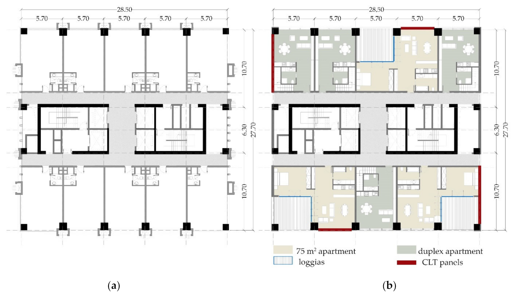
In the model, each of the seven apartments (Figure 3) and bathrooms corresponds to a heated thermal zone, while collective stairwells, corridors, and machinery rooms were considered unheated zones. Upper and lower stories were not fully modeled because they are located between two heated stories and show the same behavior as the considered one. The urban context was also geometrically modeled to simulate the shading effect of the surrounding buildings. In the current state, the external envelope from the fifth floor to the attic is a curtain wall. Windows have steel frames (with no thermal break), single glazing, and roller shutters as shading systems; internal floors are characterized by concrete slabs 12 cm thick.
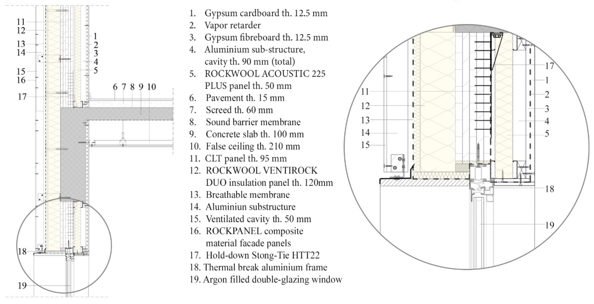
The internal walls, which separate the apartments from unheated zones, are composed of two leaves of hollow clay bricks (20 cm thick in total) with an intermediate air cavity. In the analyzed post-renovation configuration, about one-third of the glazed surface was replaced with the addition of CLT panels. These pre-assembled structural panels (U-value = 0.1496 [W/m2K], Ms = 115.1170 [kg m−2]) comprise 95 mm CLT panels, which are coated both on the internal and external side by a layer of thermal insulation (rock wool) 50 mm and 120 mm, respectively (Figure 4).
In the post-renovation state, the insertion of the panel has not reduced the glass surface (Table 4) over the internal volume compared to the as-built case due to the addition of at least three loggias per floor. All the windows were replaced with a thermal break aluminum frame with argon filled double-glazing windows (4-8-4, Ug = 2 [W/m2K]). Finally, the intermediate air gap of the internal walls was filled with insufflation thermal insulation (kT = 0.90 [W/mK]). The simulations were conducted throughout the entire year, from January to December, considering the simulation to have a natural ventilation rate of 0.4 vol/h. The internal set-point temperature for the heating and cooling season was set at 20 and 26 °C, respectively.
Figure 5 shows the results of the dynamic energy simulations in terms of heating, cooling, needs per unit net useful surface (kWh/m2) for pre- and post-renovation state. As insufficient information was available to model the thermal bridges, their contribution to the energy needs were considered by adding 10% and 5% to the results of the total heating and cooling needs, respectively. The percentage of addition to the thermal needs is consistent with the value suggested by UNI 11300 Standard for an existing non-insulated RC-framed buildings [43,44]. This percentage was applied to both pre- and post-intervention needs, although a correct design of the new façade could have eliminated or considerably reduced thermal bridges. The obtained results (Figure 5) show that, due to the interventions, the energy requirement for heating fell by 57.8% while the need for cooling, which has the major impact on global consumption, fell by 55.2%. Overall, the application of the proposed panels allowed for a reduction in global energy demand of 56%.

5.2. Structural Analysis

The case study represents a typical situation of existing structure designed only for gravity loads and without capacity design principles. It is a 19-story building with a footprint of 27.5 m × 28.5 m. The interstory height is equal to 5.4 m from the basement to the fourth floor whereas it is equal to 5 m for all the remaining floors. Two massive concrete cores are placed in the center of the plan and they are occupied by staircases, elevators, machine rooms, and cavaedium. The transversal section of the shear wall is 0.4 m. The external structure instead is a regular frame with three bays in y direction (10.7 m for external bays span and 6,3 m for the middle, respectively), and five bays (5.0 m span) in x direction. Columns cross section (rectangular or square) tapers every four or five floors, starting from 110 × 120 cm to 60 × 80 cm. On the contrary, beams’ cross section remains constant along the height (40 × 80 cm) (Table 5) and equal reinforcement was considered along building height for all the beams. The longitudinal bottom reinforcement of beams in the model consists of four rebars with diameter equal to 20 mm, while at the top there are four rebars with diameter equal to 20 mm plus two rebars with diameter equal to 18 mm. Stirrups’ diameters and spacing are equal to 9 mm and 180 mm (90 mm in lapping zones), respectively. Concrete properties reduce as well at the top of the building from C55 at the base (GB 50010) to C30 at the latest floor. Structural regularity in plan is guaranteed by the symmetry, with respect to the two horizontal orthogonal axes. All the vertical elements are continuous from the foundation to the top of the building. As a result, the structural 3D model was simplified into two 2D frames (y-z plane and x-z plane) set in series with half of the core. The members were divided into 11 groups: 10 for the columns and 1 for the beams. Members groups and reinforcement arrangement are shown in Table 5. Cracked sections were considered. Hence, the inertia of the cracked sections was obtained by reducing the inertia of the uncracked section in accordance to ASCE 41-06 by 30% for the columns, 70% for the beams, and 50% for the shear wall. The permanent structural load was taken as G1b = 3.75 kN/m2, the permanent nonstructural as G2b = 3.62 kN/m2, and the live load was considered equal to Q = 2 kN/m2 and were assigned as uniformly distributed gravity load applied to the beams of each story.
Flexural moment hinges and axial-moment hinges were defined using the “automatic hinges” command in Sap2000 to the end locations of the beams and columns, respectively. The ultimate plastic hinge rotation assumed to be 0.02 rad for the moment hinges on the beams and 0.015 rad for the axial-moment hinges on the columns. Top displacement and the interstory drift were determinate for both as-built configuration and various retrofitted configuration by means of displacement-control pushover analysis performed in SAP2000 (Computers and Structures Inc. 2013). Because the insertion of the panel may have effect on natural lighting, thermal, structural, functional, and aesthetic aspects, various configurations of the panels were tested varying their number, location, and number of connections. Among the analyzed layout, the chosen one (Figure 6) had a good agreement among all the considered parameters but mostly depended on the architectural project that concerned not only the facades of the building but also the change in destination of certain levels, the variation of apartment sizes, and the addiction of collective services.
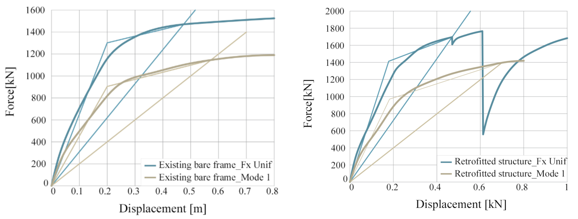
A nonlinear static analysis [45,46,47,48] was performed independently in the two directions (x-z plane and y-z plane) on the latest panels configuration (Figure 6c) which were mostly determined by the architectural needs. To reduce computation time, an equivalent truss was used to simulate the CLT panels (Figure 6b): the force-displacement behavior was modeled by a two-linear law obtained from the component model exposed above and it was assigned to the axial direction of a non-linear joint. The panels have same size (5.4 × 5.4 m) and different mechanical properties due to a different number of brackets (3, 4 or 5). Both an inverted triangular and a uniform load distribution were assigned, along the building height and increased monotonically until the onset of failure of the model. Pushover analysis results showed a moderate increase in term of strength (between 9% and 11%) and in term of elastic stiffness (around 17–18%) both in longitudinal and transversal direction (Figure 7) (Table 6).
The efficiency of the interventions depends on the connections of the panels which should yield before the structure itself. An accurate analysis should be executed on the connections. Their stiffness and hysteretic behavior depends on a large number of parameters (number and typology of nail or screws, distribution of nails, connections thickness, connections length, etc.), therefore we present here only the first guess. The equivalent viscous damping of the structure υeq was evaluated at the generic displacement D as follows:
υ e q , S = 1 4 π E D , S E S , S
All the parameters can be easily determined from the capacity curve: ED,S is the energy dissipated in a single cycle of amplitude D and ES,S is the elastic strain energy corresponding to the displacement D. Referring to an equivalent bilinear capacity curve determined from the capacity curve terms ED,S and ES,S, which can be determined as follows:
E D , S b i l i n e a r = 4 F s y D D s y F s D
E S , S = 1 2 D F S D
With D top as displacement reached from the structure; Fs (D) the force corresponding to displacement D; Dsy displacement at yielding; and Fsy the yielding force.

6. Conclusions

This paper presented and described the initial stages of a displacement-based procedure to design an innovative and versatile refurbishment solution for RC-framed structures in which the CLT panels are used to set up a new envelope for the building or they can be used as a new infill shear wall to improve both seismic and thermal behavior of the building. The first objective was to achieve a defined target displacement or a prescribed interstory drift by increasing both stiffness and dissipation, and at the same time, reducing the base shear. A second objective was the improvement of various aspects of the architectural project, related to natural ventilation and natural lighting (Figure 8), also improving the energy aspects through a new skin for the building.
The entire high-rise building was redesigned using a mix of three different apartment sizes (50, 75, and 100 m2), with the addition of outdoor spaces, balconies, duplexes, and new services (Figure 9). Dynamic thermal and lighting simulations were performed on an as -built and post-renovation configuration on a typical floor plan consisting of seven apartments. In particular, the overall annual energy needs for heating and cooling decreased for the considered floor by about 66%, with the major energy savings being observed during the summer period. As regards to the lighting simulations, it was shown that despite the insertion of the panels, good levels of natural lighting were maintained, while in certain cases, the insertion of the loggias allowed natural light to reach the inner areas of the floor. As briefly shown, several tests were performed previously to fully understand the change in response of one-story one-bay RC frame subjected to in-plan loads due to the insertion of a CLT panel. Lastly, analyses were conducted on two 2D frames coupled with half of the concrete core, and the CLT infill allowed the structure to achieve a lower interstory drift and a higher peak load.
The performed analysis seems to confirm the possibility to obtain the seismic, energetic, and architectural upgrade of existing RC buildings using CLT panels. The authors are aware that a more detailed investigation should be made, for instance, to fully investigate the interaction between the concrete structure and panels when they are infilled [21], or how CLT panels act when applied outside of the structure, how new dissipation devices may be designed and added to the system to allow CLT panels to act correctly from the outside, allowing the damage to be grouped into a few sacrificial elements, etc.

Author Contributions

Conceptualization, C.P.C., C.N. and B.B.; methodology, C.P.C., C.N. and B.B.; software, C.P.C.; formal analysis, C.P.C.; data curation, C.P.C. and A.P.; writing—original draft preparation, C.P.C.; writing—review and editing, C.P.C., Z.L., B.B., A.P. and C.P.C.; visualization, C.P.C., A.P.; supervision, C.P.C. and B.B. All authors have read and agreed to the published version of the manuscript.

Funding

This research received no external funding.

Institutional Review Board Statement

Not applicable.

Informed Consent Statement

Not applicable.

Data Availability Statement

All the resulting data are contained in this article.

Conflicts of Interest

The authors declare no conflict of interest. The funders had no role in the design of the study; in the collection, analyses, or interpretation of data; in the writing of the manuscript, or in the decision to publish the results.

References

  1. Hamnett, C. Is Chines urbanisation unique? Urban Stud. 2020, 57, 690–700. [Google Scholar] [CrossRef]
  2. Bjørnfot, A.; Boggian, F.; Nygård, A.S.; Tomasi, R. Strengthening of traditional buildings with slim panels of cross-laminated timber (CLT). In Proceedings of the 4th International Conference on Structural Health Assessment of Timber Structures (SHATIS’17), Istanbul, Turkey, 20–22 September 2017. [Google Scholar]
  3. Guerrini, G.; Damiani, N.; Miglietta, M.; Graziotti, F. Cyclic response of masonry piers retrofitted with timber frames and boards. Struct. Build. 2021, 174, 372–388. [Google Scholar] [CrossRef]
  4. Riccadonna, D.; Giongo, I.; Schiro, G.; Rizzi, E.; Parisi, M.A. Experimental shear testing of timber-masonry dry connections for the seismic retrofit of unreinforced masonry shear walls. Constr. Build. Mater. 2019, 211, 52–72. [Google Scholar] [CrossRef]
  5. Cassol, D.; Giongo, I.; Ingham, J.; Dizhur, D. Seismic out-of-plane retrofit of URM walls using timber strong-backs. Constr. Build. Mater. 2021, 269, 121237. [Google Scholar] [CrossRef]
  6. Giaretton, M.; Dizhur, D.; Ingham, J.M. Shaking table testing of as-built and retrofitted clay brick URM cavity-walls. Eng. Struct. 2016, 125, 70–79. [Google Scholar] [CrossRef]
  7. Pozza, L.; Evangelista, F.; Scotta, R. CLT used as seismic strengthener for existing masonry walls. In Proceeding of the XVII CONVEGNO ANIDIS 2017, Pistoia, Italia, 17–21 September 2017. [Google Scholar]
  8. Miglietta, M.; Damiani, N.; Guerrini, G. Full-scale shake-table tests on two unreinforced masonry cavity-wall buildings: Effect of an innovative timber retrofit. Bull. Earthq. Eng. 2021, 19, 2561–2596. [Google Scholar] [CrossRef]
  9. Miglietta, M.; Damiani, N.; Grottoli, L.; Guerrini, G.; Graziotti, F. Shake-table investigation of a timber retrofit solution for unreinforced masonry cavity-wall buildings. In Proceedings of the XVIII CONVEGNO ANIDIS 2019, Ascoli Piceno, Italia, 15–19 September 2019. [Google Scholar]
  10. Damiani, N.; Miglietta, M.; Guerrini, G.; Graziotti, F. An innovative timber system for the seismic retrofit of unreinforced brick masonry buildings. In Brick and Block Masonry—From Historical to Sustainable Masonry. Proceedings of the 17th International Brick/Block Masonry Conference (17thIB2MaC 2020), Kraków, Poland, 5–8 July 2020; CRC Press: London, UK, 2020. [Google Scholar]
  11. Iuorio, O.; Duada, J.A.; Lourenço, P.B. Experimental evaluation of out-of-plane strength of masonry walls retrofitted with oriented strand board. Constr. Build. Mater. 2021, 269, 121358. [Google Scholar] [CrossRef]
  12. Maduh, U.J.; Sheddem, D.; Ingham, J.; Dizhur, D. In-plane Testing of URM Wall Panels Retrofitted Using Timber strong-backs. In Proceedings of the Australian Earthquake Engineering Society 2019 Conference, Newcastle, NSW, Australia, 29 November–1 December 2019. [Google Scholar]
  13. Reyes, J.C.; Smith-Pardo, J.P.; Yamin, L.E.; Galvis, F.A.; Sandoval, J.D.; Ganzalez, C.D.; Correal, J.F. In-plane seismic behavior of full-scale earthen walls with openings retrofitted with timber elements and vertical tensors. Bull. Earthq. Eng. 2019, 17, 4193–4215. [Google Scholar] [CrossRef]
  14. Yamin, L.E.; Phillips, C.A.; Reyes, J.C.; Ruiz, D.M. Seismic behavior and rehabilitation alternatives for adobe and rammed earth buildings. In Proceedings of the 13th world Conference on Earthquake Engineering, WCEE 2004, Vancouver, BC, Canada, 1–6 August 2004. [Google Scholar]
  15. Borri, A.; Sisti, R.; Corradi, M. Seismic retrofit of stone walls with timber panels and steel wire ropes. Struct. Build. 2021, 174, 359–371. [Google Scholar] [CrossRef]
  16. Contiguglia, C.P.; Bergami, A.V.; Fiorentino, G.; Lavorato, D.; Nuti, C.; Lai, Z.; Briseghella, B. Chinese high rise reinforced concrete building retrofitted with CLT Panels. In Proceedings of the Seventh International Symposium on Life-Cycle Civil Engineering, IALCEE2020, Shanghai, China, 27–30 October 2020. [Google Scholar]
  17. Sustersic, I.; Dujic, B. Seismic strengthening of existing buildings with cross laminated timber panels. In Proceedings of the World Conference of Timber Engineering, WCTE 2012, Auckland, New Zeeland, 16–19 July 2012. [Google Scholar]
  18. Sustersic, I.; Dujic, B. Seismic Strengthening of Existing Concrete and Masonry Buildings with Crosslam Timber Panels. Mater. Jt. Timber Struct. Recent Dev. Technol. RILEM Bookser. 2014, 9, 713–723. [Google Scholar]
  19. Sustersic, I.; Dujic, B. Seismic Shaking Table Testing of a Reinforced Concrete Frame with Masonry Infill Strengthened with Cross Laminated Timber Panels. In Proceedings of the World Conference on Timber Engineering, WCTE 2014, Quebec, QC, Canada, 10–14 August 2014. [Google Scholar]
  20. Haba, R.; Kitamori, A.; Mori, T.; Fukuhara, T.; Kurihara, T.; Isoda, H. Development of CLT panels bond-in method for seismic retrofitting of RC frame structure. J. Struct. Constr. Eng. 2016, 81, 1299–1308. [Google Scholar] [CrossRef]
  21. Stazi, F.; Serpilli, M.; Maracchini, G.; Pavone, A. An experimental and numerical study on CLT panels used as infill shear walls for RC buildings retrofit. Constr. Build. Mater. 2019, 211, 606–616. [Google Scholar] [CrossRef]
  22. Smiroldo, F.; Piazza, M.; Giongo, I. Seismic retrofit of masonry infilled frames by using timber panels. In Proceedings of the 17th world Conference on Earthquake Engineering, WCEE 2020, Sendai, Japan, 13–18 September 2020. [Google Scholar]
  23. Margani, G.; Evola, G.; Tardo, C.; Marino, E.M. Energy, seismic, and architectural renovation of RC framed buildings with prefabricated timber panels. Sustainability 2020, 12, 4845. [Google Scholar] [CrossRef]
  24. Dalla Mora, T.; Righi, A.; Peron, F.; Romagnoli, P. Evaluation of thermal performance, environmental impact, and cost effectiveness of an XLam component for retrofitting in existing buildings. In Mediterranean Green Buildings & Renewable Energy; Springer: Berlin/Heidelberg, Germany, 2017; pp. 643–656. [Google Scholar]
  25. Marini, A.; Passoni, C.; Belleri, A.; Feroldi, F.; Preti, M.; Metelli, G.; Riva, P.; Giuriani, E.; Plizzari, G. Combining seismic retrofit with energy refurbishment for the sustainable renovation of RC buildings: A proof of concept. Eur. J. Environ. Civ. Eng. 2015, 110. [Google Scholar] [CrossRef]
  26. Ascione, F.; Ceroni, F.; De Masi, R.F.; de’ Rossi, F. Historical buildings: Multidisciplinary approach to structural/energy diagnosis and performance assessment. Appl. Energy 2017, 185, 1517–1528. [Google Scholar] [CrossRef]
  27. Duan, H.; Hueste, M.B. Seismic performance of a reinforced concrete frame building in China. Eng. Struct. 2012, 41, 77–89. [Google Scholar] [CrossRef]
  28. Su, C.; Madami, H.; Palm, B. Heating solutions for residential buildings in China: Current status and future Outlook. Energy Convers. Manag. 2018, 177, 493–510. [Google Scholar] [CrossRef]
  29. Yoshino, H.; Yoshino, Y.; Zhang, Q.; Mochina, A.; Li, N.; Li, Z.; Miyasaka, H. Indoor thermal environment and energy saving for urban residential buildings in China. Energy Build. 2006, 38, 1308–1319. [Google Scholar] [CrossRef]
  30. Computers and Structure Inc. SAP2000 NonLinear Version 10 (2005) User’s Reference Manual; Computers and structures Inc.: Berkeley, CA, USA, 2005. [Google Scholar]
  31. Brandner, R.; Flatscher, G.; Ringhofer, A.; Schickhofer, G.; Thiel, A. Cross laminated timber (CLT): Over-view and development. Eur. J. Wood Wood Prod. 2016, 74, 331–351. [Google Scholar] [CrossRef]
  32. Ashtari, S. In-plane Stiffness of Cross-laminated Timber Floors. Master’s Thesis, University of British Columbia, Vancouver, BC, Canada, 2012. [Google Scholar]
  33. Gavric, I.; Fragiacomo, M.; Ceccotti, A. Cyclic behaviour of typical metal connectors for cross laminated (CLT) structures. Mater. Struct. 2015, 48, 1841–1857. [Google Scholar] [CrossRef]
  34. Izzi, M.; Polastri, A.; Fragiacomo, M. Advanced modelling of CLT wall systems for earthquake resistant timber structures. In Proceedings of the 3rd International Network on Timber Engineering Research (INTER) Meeting, Graz, Austria, 16 August–31 December 2016; pp. 1–14. [Google Scholar]
  35. Tamagnone, G.; Rinaldin, G.; Frangiacomo, M. A simplified procedure for non−linear design of the metal connectors in XLam timber walls subjected to gravity and lateral loads. In Proceedings of the XVI Convegno ANIDIS L’ ingegneria Sismica in Italia, L’Aquila, Italy, 13–17 September 2015. [Google Scholar]
  36. Gavric, I.; Fragiacomo, M.; Ceccotti, A. Cyclic behavior of typical screwed connections for cross-laminated (CLT) structures. Eur. J. Wood Wood Prod. 2015, 73, 179–191. [Google Scholar] [CrossRef]
  37. Gavric, I.; Fragiacomo, M.; Ceccotti, A. Cyclic Behavior of CLT Wall Systems: Experimental Tests and Analytical Prediction Models. J. Struct. Eng. 2015, 141, 04015034. [Google Scholar] [CrossRef]
  38. Pozza, L.; Savoia, M.; Franco, L.; Saetta, A.; Talledo, D. Effect of different modelling approaches on the prediction of the seismic response of multi-storey CLT buildings. Int. J. Comp. Meth. Exp. Meas. 2017, 5, 953–965. [Google Scholar] [CrossRef]
  39. Cheshmehzangi, A.; Butters, C. Chinese urban residential blocks: Towards improved environmental and living qualities. Urban Des. Int. 2017, 22, 219–235. [Google Scholar] [CrossRef]
  40. Chen, S.; Li, N.; Yoshinoc, H.; Guana, J.; Levine, M.D. Statistical analyses on winter energy consumption characteristics of residential buildings in some cities of China. Energy Build. 2011, 43, 1063–1070. [Google Scholar] [CrossRef]
  41. Chen, S.; Yoshinoc, H.; Li, N. Statistical analyses on summer energy consumption characteristics of residential buildings in some cities of China. Energy Build. 2010, 42, 136–146. [Google Scholar] [CrossRef]
  42. ACCA Software, S.p.A. TerMus-PLUS V.5.00.a BIM (2021). Available online: https://www.acca.it/software-analisi-simulazione-energetica-dinamica-edifici (accessed on 12 August 2021).
  43. Ente nazionale italiano di unificazione. Prestazione Termica di Finestre, Porte e Chiusure Oscuranti–Calcolo Della Trasmittanza Termica. In UNI 10077-1; UNI: Roma, Italy, 2018. [Google Scholar]
  44. Ente nazionale italiano di unificazione. Prestazioni Energetiche Degli Edifici Parte 1: Determinazione del Fabbisogno di Energia Termica Dell’edificio per la Climatizzazione Estiva ed Invernale. In UNI/TS 11300-1; UNI: Roma, Italy, 2008. [Google Scholar]
  45. Bergami, A.V.; Forte, A.; Lavorato, D.; Nuti, C. Proposal of a incremental modal pushover analysis (IMPA). Earthq. Struct. 2017, 13, 539–549. [Google Scholar]
  46. Lavorato, D.; Nuti, C.; Santini, S.; Briseghella, B.; Xue, J. A repair and retrofitting intervention to improve plastic dissipation and shear strength of Chinese RC bridges. In IABSE Symposium Report; International Association for Bridge and Structural Engineering: Zürich, Switzerland, 2015; Volume 105, pp. 1–6. [Google Scholar]
  47. Xue, J.; Lavorato, D.; Bergami, A.V.; Nuti, C.; Briseghella, B.; Marano, G.C.; Santini, S. Severely damaged reinforced concrete circular columns repaired by turned steel rebar and high-performance concrete jacketing with steel or polymer fibers. Appl. Sci. 2018, 8, 1671. [Google Scholar] [CrossRef] [Green Version]
  48. Lavorato, D.; Bergami, A.V.; Nuti, C.; Briseghella, B.; Xue, J.; Tarantino, A.M.; Santini, S. Ultra-high-performance fibre-reinforced concrete jacket for the repair and the seismic retrofitting of Italian and Chinese RC bridges. In Proceedings of the 6th International Conference on Computational Methods in Structural Dynamics and Earthquake Engineering, Rhodes Island, Greece, 15–17 June 2017; Volume 1, pp. 2149–2160. [Google Scholar]
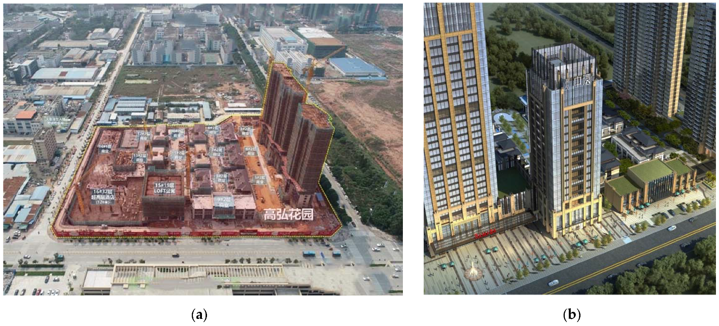
Figure 1. (a) Aerial photography of the construction site and (b) aerial render of the case study neighborhood “Gaohong Century Center”.
Sustainability 13 09667 g001
Figure 2. (a) Hold-down HTT22 and brackets AE116 90 × 48 × 3 × 116mm; (b) typical hysteresis loops of a hold-down loaded in tension (asymmetric curve) and of a bracket loaded in shear (symmetric curve).
Sustainability 13 09667 g002
Figure 3. (a) Comparison between as-built plan distribution and (b) after the intervention.
Sustainability 13 09667 g003
Figure 4. Detailed cross-section of the rehabilitation solution with CLT panels infilled and detailed cross section of the designed window attachment joint.
Sustainability 13 09667 g004
Figure 5. Comparison between heating and cooling needs during the year before and after the intervention.
Sustainability 13 09667 g005
Figure 6. (a) Section; (b) FEM model; and (c) final result of east elevation of the case study.
Sustainability 13 09667 g006
Figure 7. Results of the non-linear static analyses in terms of base shear against roof drift for the bare structure.
Sustainability 13 09667 g007
Figure 8. (a) Daylight factor detected in September (12:00 a.m.) with partially overcast sky for as-built configuration; (b) (c) two post-renovation model floorplans.
Sustainability 13 09667 g008
Figure 9. (a) Render images of as-built east elevation of the case study; (b) post renovation east elevation of the case study.
Sustainability 13 09667 g009
Table 1. Material parameters of the CLT panels. Ex, Ey, and Ez denote the moduli of elasticity of the CLT panel; Gxy, Gxz, and Gyz the shear moduli while vxy, vxz, and vyz are the Poisson’s ratios.
Strength ValuesElastic Modulus
fm,kft,0,kfc,0,kExEyEz
MpaMpaMpaGPaGPaGPa
2414217.104.800.40
Shear ModulusPoisson’s Ratio
GxyGxzGyzυxyυxzυyz
GPaGPaGPa---
0.650.500.100.0750.3640.380
Table 2. Mechanical properties of hold-down and angle brackets in the model.
HOLD-DOWN_HTT22
KelFyKplFmax
kN/mmkNkN/mmkN
shear0.919.760.1313.89
tension4.6539.130.7047.78
BRACKET_BMF90 × 48 × 3 × 116
KelFyKplFmax
kN/mmkNkN/mmkN
shear2.0922.980.3526.85
tension2.5219.220.4223.47
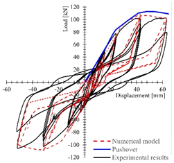
Table 3. Wall 1—model on Sap2000 with linear shell + nonlinear connections; Wall 1,2,3—comparison between lab test (black lines), numerical model (red dashed lines), and pushover curve (blue lines).
Wall configuration Sustainability 13 09667 i001 Sustainability 13 09667 i002 Sustainability 13 09667 i003
Dimension2950 × 2950 × 85 mm2950 × 2950 × 85 mm2950 × 2950 × 85 mm
Vertical Load18.5 kN/m18.5 kN/m9.25 kN/m
Hold-down× 2 HTT22
12 nails φ4 × 60 mm
× 2 HTT22
12 nails φ4 × 60 mm
× 2 HTT22
12 nails φ4 × 60 mm
Brackets× 2 AE116
90 × 48 × 3 × 116 mm
11 nails φ4 × 60 mm
× 4 AE116
90 × 48 × 3 × 116 mm
11 nails φ4 × 60 mm
× 2 AE116
90 × 48 × 3 × 116 mm
11 nails φ4 × 60 mm
Results Sustainability 13 09667 i004 Sustainability 13 09667 i005 Sustainability 13 09667 i006
Table 4. Comparison between indoor volume and horizontal and vertical surfaces in as-built and post renovation configuration.
As-Built Post Renovation
Indoor volume3 368.77 m3 3 029.63 m3
Indoor floor area676.45 m2 608.32 m2
Wall surface bordering with the outdoor 358.71 m2 352.10 m2
Glazed surface bordering with the outdoor273.44 m2 245.77 m2
Number of apartments per floor 107
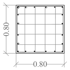
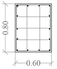
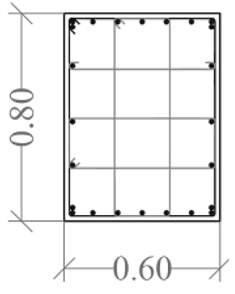
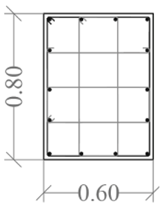
Table 5. Structural members grouping and cross section details with reinforcement arrangement (longitudinal bars and stirrups). KZ1 identifies lateral column, KZ2 refers to central columns.
Columns −1/4 floorColumns 5/9 floor
Sustainability 13 09667 i007 Sustainability 13 09667 i008 Sustainability 13 09667 i009 Sustainability 13 09667 i010
Column IDKZ1KZ2KZ1KZ2
Long.
Rebar
4ϕ22 + 16ϕ204ϕ25 + 28ϕ224ϕ22 + 16ϕ204ϕ22 + 20ϕ20
Stirrupsϕ10
100
ϕ10
90
ϕ10
100
ϕ10
200/200
Columns 10/14 floorColumns 15/19 floor
Sustainability 13 09667 i011 Sustainability 13 09667 i012 Sustainability 13 09667 i013 Sustainability 13 09667 i014 Sustainability 13 09667 i015 Sustainability 13 09667 i016
Column IDKZ1KZ2KZ1KZ2
Long.
Rebar
4ϕ22 + 16ϕ204ϕ22 + 22ϕ188ϕ25 + 6ϕ2018ϕ25 + 6ϕ208ϕ20 + 6ϕ1814ϕ25 + 6ϕ20
Stirrupsϕ8
100
ϕ8
100
ϕ8
100
ϕ8
100
ϕ8
90/180
ϕ8
90/180
Table 6. Push-over analysis results on the existing bare frame and on retrofitted structure.
Existing bare frame F UNIFDFKED,SES,Sveq,s
mkNkN/mKJKJ-
00 1284340.753.0
Dsy,Fsyy0.213006500.0
D,F(D)max0.514503085.1
Existing bare frame MODE 1DFKED,SES,Sveq,s
mkNkN/mKJKJ[-]
00 1153,6331,22,7
Dsy,Fsyy0.29004500.0
D,F(D)max0.611501996.5
Retrofitted structure F UNIFDFKED,SES,Sveq,s
mkNkN/mKJKJ-
00 1298382.52.7
Dsy,Fsyy0.214207675.7
D,F(D)max0.517003777.8
Retrofitted structure MODE 1DFKED,SES,Sveq,s
mkNkN/mKJKJ-
00 16964832,8
Dsy,Fsyy0.210005263,2
D,F(D)max0.714002029,0
Publisher’s Note: MDPI stays neutral with regard to jurisdictional claims in published maps and institutional affiliations.