
Chinese High Rise Reinforced Concrete Building Retrofitted with CLT Panels


 and
and 
Abstract
:1. Introduction
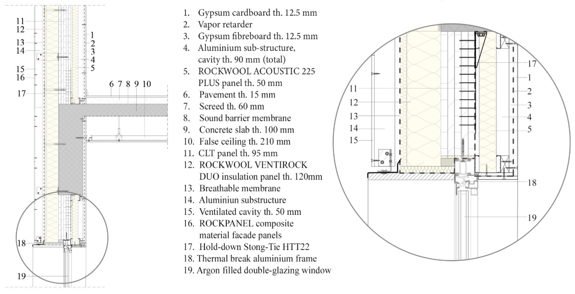
2. Rehabilitation Solution
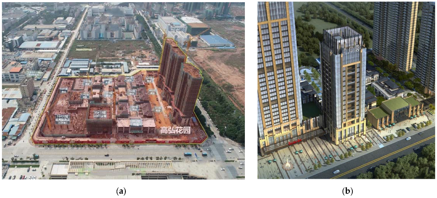
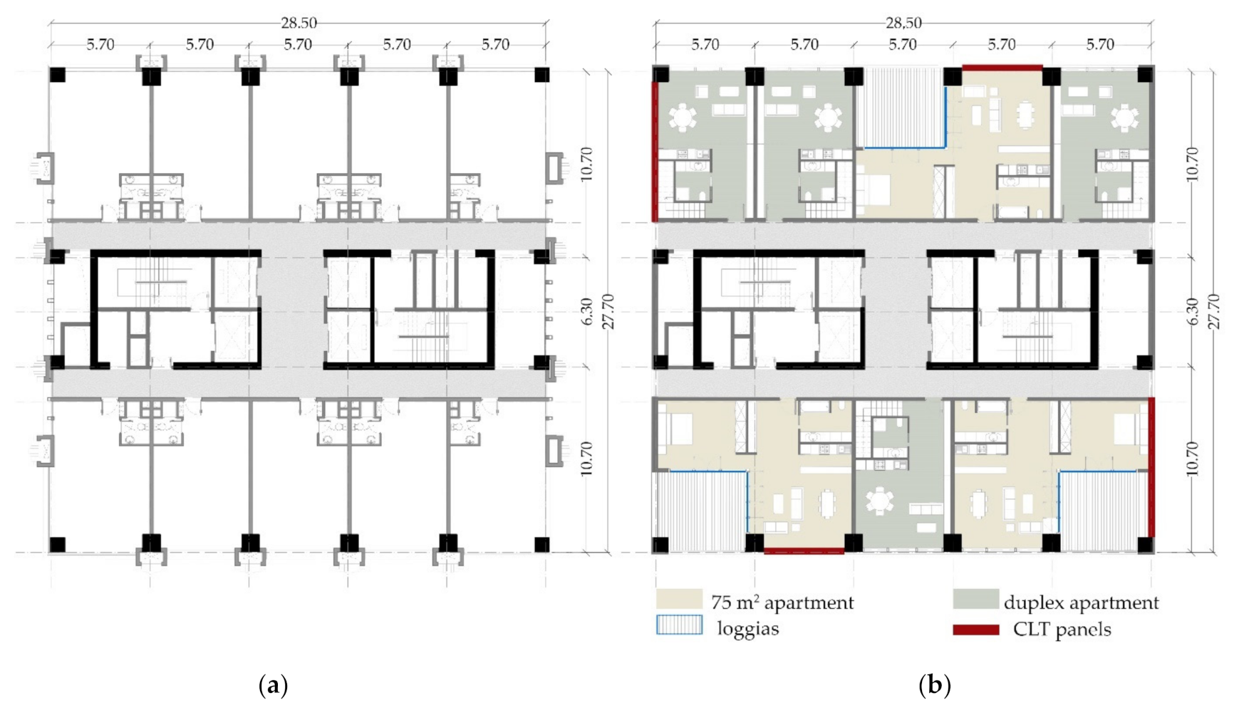
3. Case Study
4. Numerical Model
Analysis on Representative Frames
5. Results
5.1. Dynamic Thermal Simulation
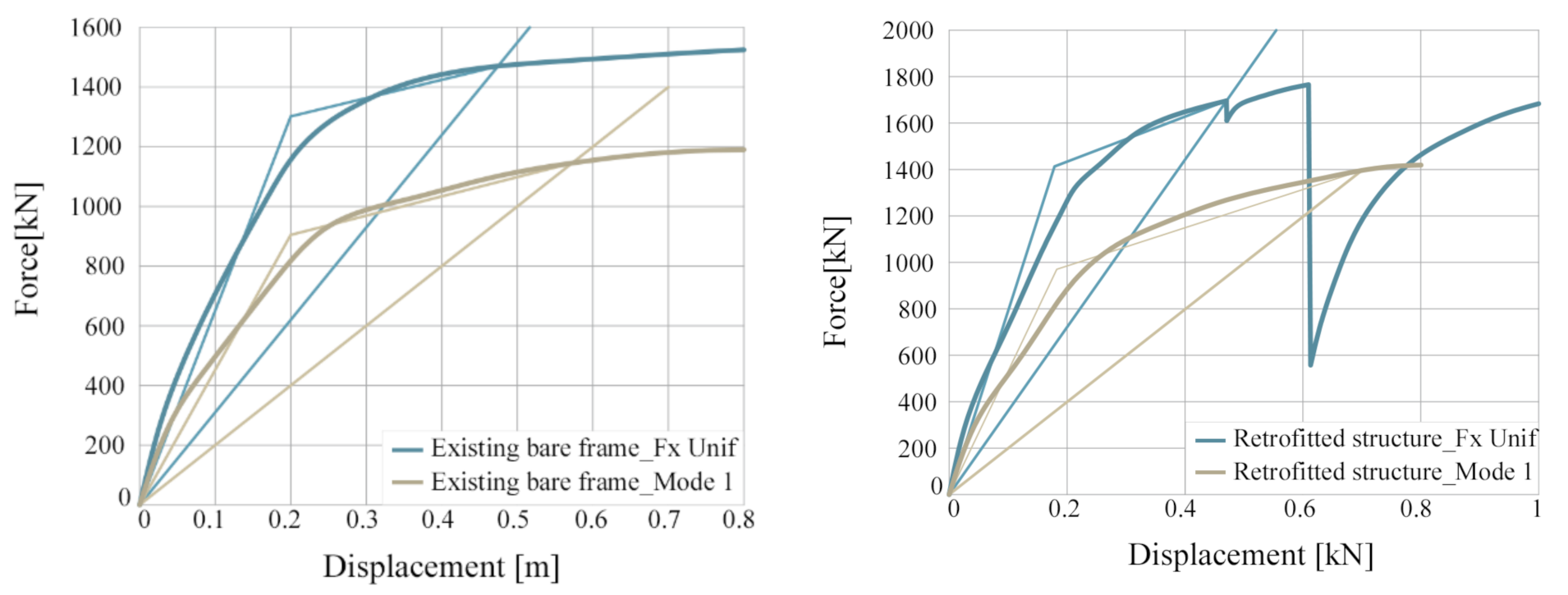
5.2. Structural Analysis
6. Conclusions
Author Contributions
Funding
Institutional Review Board Statement
Informed Consent Statement
Data Availability Statement
Conflicts of Interest
References
- Hamnett, C. Is Chines urbanisation unique? Urban Stud. 2020, 57, 690–700. [Google Scholar] [CrossRef]
- Bjørnfot, A.; Boggian, F.; Nygård, A.S.; Tomasi, R. Strengthening of traditional buildings with slim panels of cross-laminated timber (CLT). In Proceedings of the 4th International Conference on Structural Health Assessment of Timber Structures (SHATIS’17), Istanbul, Turkey, 20–22 September 2017. [Google Scholar]
- Guerrini, G.; Damiani, N.; Miglietta, M.; Graziotti, F. Cyclic response of masonry piers retrofitted with timber frames and boards. Struct. Build. 2021, 174, 372–388. [Google Scholar] [CrossRef]
- Riccadonna, D.; Giongo, I.; Schiro, G.; Rizzi, E.; Parisi, M.A. Experimental shear testing of timber-masonry dry connections for the seismic retrofit of unreinforced masonry shear walls. Constr. Build. Mater. 2019, 211, 52–72. [Google Scholar] [CrossRef]
- Cassol, D.; Giongo, I.; Ingham, J.; Dizhur, D. Seismic out-of-plane retrofit of URM walls using timber strong-backs. Constr. Build. Mater. 2021, 269, 121237. [Google Scholar] [CrossRef]
- Giaretton, M.; Dizhur, D.; Ingham, J.M. Shaking table testing of as-built and retrofitted clay brick URM cavity-walls. Eng. Struct. 2016, 125, 70–79. [Google Scholar] [CrossRef]
- Pozza, L.; Evangelista, F.; Scotta, R. CLT used as seismic strengthener for existing masonry walls. In Proceeding of the XVII CONVEGNO ANIDIS 2017, Pistoia, Italia, 17–21 September 2017. [Google Scholar]
- Miglietta, M.; Damiani, N.; Guerrini, G. Full-scale shake-table tests on two unreinforced masonry cavity-wall buildings: Effect of an innovative timber retrofit. Bull. Earthq. Eng. 2021, 19, 2561–2596. [Google Scholar] [CrossRef]
- Miglietta, M.; Damiani, N.; Grottoli, L.; Guerrini, G.; Graziotti, F. Shake-table investigation of a timber retrofit solution for unreinforced masonry cavity-wall buildings. In Proceedings of the XVIII CONVEGNO ANIDIS 2019, Ascoli Piceno, Italia, 15–19 September 2019. [Google Scholar]
- Damiani, N.; Miglietta, M.; Guerrini, G.; Graziotti, F. An innovative timber system for the seismic retrofit of unreinforced brick masonry buildings. In Brick and Block Masonry—From Historical to Sustainable Masonry. Proceedings of the 17th International Brick/Block Masonry Conference (17thIB2MaC 2020), Kraków, Poland, 5–8 July 2020; CRC Press: London, UK, 2020. [Google Scholar]
- Iuorio, O.; Duada, J.A.; Lourenço, P.B. Experimental evaluation of out-of-plane strength of masonry walls retrofitted with oriented strand board. Constr. Build. Mater. 2021, 269, 121358. [Google Scholar] [CrossRef]
- Maduh, U.J.; Sheddem, D.; Ingham, J.; Dizhur, D. In-plane Testing of URM Wall Panels Retrofitted Using Timber strong-backs. In Proceedings of the Australian Earthquake Engineering Society 2019 Conference, Newcastle, NSW, Australia, 29 November–1 December 2019. [Google Scholar]
- Reyes, J.C.; Smith-Pardo, J.P.; Yamin, L.E.; Galvis, F.A.; Sandoval, J.D.; Ganzalez, C.D.; Correal, J.F. In-plane seismic behavior of full-scale earthen walls with openings retrofitted with timber elements and vertical tensors. Bull. Earthq. Eng. 2019, 17, 4193–4215. [Google Scholar] [CrossRef]
- Yamin, L.E.; Phillips, C.A.; Reyes, J.C.; Ruiz, D.M. Seismic behavior and rehabilitation alternatives for adobe and rammed earth buildings. In Proceedings of the 13th world Conference on Earthquake Engineering, WCEE 2004, Vancouver, BC, Canada, 1–6 August 2004. [Google Scholar]
- Borri, A.; Sisti, R.; Corradi, M. Seismic retrofit of stone walls with timber panels and steel wire ropes. Struct. Build. 2021, 174, 359–371. [Google Scholar] [CrossRef]
- Contiguglia, C.P.; Bergami, A.V.; Fiorentino, G.; Lavorato, D.; Nuti, C.; Lai, Z.; Briseghella, B. Chinese high rise reinforced concrete building retrofitted with CLT Panels. In Proceedings of the Seventh International Symposium on Life-Cycle Civil Engineering, IALCEE2020, Shanghai, China, 27–30 October 2020. [Google Scholar]
- Sustersic, I.; Dujic, B. Seismic strengthening of existing buildings with cross laminated timber panels. In Proceedings of the World Conference of Timber Engineering, WCTE 2012, Auckland, New Zeeland, 16–19 July 2012. [Google Scholar]
- Sustersic, I.; Dujic, B. Seismic Strengthening of Existing Concrete and Masonry Buildings with Crosslam Timber Panels. Mater. Jt. Timber Struct. Recent Dev. Technol. RILEM Bookser. 2014, 9, 713–723. [Google Scholar]
- Sustersic, I.; Dujic, B. Seismic Shaking Table Testing of a Reinforced Concrete Frame with Masonry Infill Strengthened with Cross Laminated Timber Panels. In Proceedings of the World Conference on Timber Engineering, WCTE 2014, Quebec, QC, Canada, 10–14 August 2014. [Google Scholar]
- Haba, R.; Kitamori, A.; Mori, T.; Fukuhara, T.; Kurihara, T.; Isoda, H. Development of CLT panels bond-in method for seismic retrofitting of RC frame structure. J. Struct. Constr. Eng. 2016, 81, 1299–1308. [Google Scholar] [CrossRef]
- Stazi, F.; Serpilli, M.; Maracchini, G.; Pavone, A. An experimental and numerical study on CLT panels used as infill shear walls for RC buildings retrofit. Constr. Build. Mater. 2019, 211, 606–616. [Google Scholar] [CrossRef]
- Smiroldo, F.; Piazza, M.; Giongo, I. Seismic retrofit of masonry infilled frames by using timber panels. In Proceedings of the 17th world Conference on Earthquake Engineering, WCEE 2020, Sendai, Japan, 13–18 September 2020. [Google Scholar]
- Margani, G.; Evola, G.; Tardo, C.; Marino, E.M. Energy, seismic, and architectural renovation of RC framed buildings with prefabricated timber panels. Sustainability 2020, 12, 4845. [Google Scholar] [CrossRef]
- Dalla Mora, T.; Righi, A.; Peron, F.; Romagnoli, P. Evaluation of thermal performance, environmental impact, and cost effectiveness of an XLam component for retrofitting in existing buildings. In Mediterranean Green Buildings & Renewable Energy; Springer: Berlin/Heidelberg, Germany, 2017; pp. 643–656. [Google Scholar]
- Marini, A.; Passoni, C.; Belleri, A.; Feroldi, F.; Preti, M.; Metelli, G.; Riva, P.; Giuriani, E.; Plizzari, G. Combining seismic retrofit with energy refurbishment for the sustainable renovation of RC buildings: A proof of concept. Eur. J. Environ. Civ. Eng. 2015, 110. [Google Scholar] [CrossRef]
- Ascione, F.; Ceroni, F.; De Masi, R.F.; de’ Rossi, F. Historical buildings: Multidisciplinary approach to structural/energy diagnosis and performance assessment. Appl. Energy 2017, 185, 1517–1528. [Google Scholar] [CrossRef]
- Duan, H.; Hueste, M.B. Seismic performance of a reinforced concrete frame building in China. Eng. Struct. 2012, 41, 77–89. [Google Scholar] [CrossRef]
- Su, C.; Madami, H.; Palm, B. Heating solutions for residential buildings in China: Current status and future Outlook. Energy Convers. Manag. 2018, 177, 493–510. [Google Scholar] [CrossRef]
- Yoshino, H.; Yoshino, Y.; Zhang, Q.; Mochina, A.; Li, N.; Li, Z.; Miyasaka, H. Indoor thermal environment and energy saving for urban residential buildings in China. Energy Build. 2006, 38, 1308–1319. [Google Scholar] [CrossRef]
- Computers and Structure Inc. SAP2000 NonLinear Version 10 (2005) User’s Reference Manual; Computers and structures Inc.: Berkeley, CA, USA, 2005. [Google Scholar]
- Brandner, R.; Flatscher, G.; Ringhofer, A.; Schickhofer, G.; Thiel, A. Cross laminated timber (CLT): Over-view and development. Eur. J. Wood Wood Prod. 2016, 74, 331–351. [Google Scholar] [CrossRef]
- Ashtari, S. In-plane Stiffness of Cross-laminated Timber Floors. Master’s Thesis, University of British Columbia, Vancouver, BC, Canada, 2012. [Google Scholar]
- Gavric, I.; Fragiacomo, M.; Ceccotti, A. Cyclic behaviour of typical metal connectors for cross laminated (CLT) structures. Mater. Struct. 2015, 48, 1841–1857. [Google Scholar] [CrossRef]
- Izzi, M.; Polastri, A.; Fragiacomo, M. Advanced modelling of CLT wall systems for earthquake resistant timber structures. In Proceedings of the 3rd International Network on Timber Engineering Research (INTER) Meeting, Graz, Austria, 16 August–31 December 2016; pp. 1–14. [Google Scholar]
- Tamagnone, G.; Rinaldin, G.; Frangiacomo, M. A simplified procedure for non−linear design of the metal connectors in XLam timber walls subjected to gravity and lateral loads. In Proceedings of the XVI Convegno ANIDIS L’ ingegneria Sismica in Italia, L’Aquila, Italy, 13–17 September 2015. [Google Scholar]
- Gavric, I.; Fragiacomo, M.; Ceccotti, A. Cyclic behavior of typical screwed connections for cross-laminated (CLT) structures. Eur. J. Wood Wood Prod. 2015, 73, 179–191. [Google Scholar] [CrossRef]
- Gavric, I.; Fragiacomo, M.; Ceccotti, A. Cyclic Behavior of CLT Wall Systems: Experimental Tests and Analytical Prediction Models. J. Struct. Eng. 2015, 141, 04015034. [Google Scholar] [CrossRef]
- Pozza, L.; Savoia, M.; Franco, L.; Saetta, A.; Talledo, D. Effect of different modelling approaches on the prediction of the seismic response of multi-storey CLT buildings. Int. J. Comp. Meth. Exp. Meas. 2017, 5, 953–965. [Google Scholar] [CrossRef]
- Cheshmehzangi, A.; Butters, C. Chinese urban residential blocks: Towards improved environmental and living qualities. Urban Des. Int. 2017, 22, 219–235. [Google Scholar] [CrossRef]
- Chen, S.; Li, N.; Yoshinoc, H.; Guana, J.; Levine, M.D. Statistical analyses on winter energy consumption characteristics of residential buildings in some cities of China. Energy Build. 2011, 43, 1063–1070. [Google Scholar] [CrossRef]
- Chen, S.; Yoshinoc, H.; Li, N. Statistical analyses on summer energy consumption characteristics of residential buildings in some cities of China. Energy Build. 2010, 42, 136–146. [Google Scholar] [CrossRef]
- ACCA Software, S.p.A. TerMus-PLUS V.5.00.a BIM (2021). Available online: https://www.acca.it/software-analisi-simulazione-energetica-dinamica-edifici (accessed on 12 August 2021).
- Ente nazionale italiano di unificazione. Prestazione Termica di Finestre, Porte e Chiusure Oscuranti–Calcolo Della Trasmittanza Termica. In UNI 10077-1; UNI: Roma, Italy, 2018. [Google Scholar]
- Ente nazionale italiano di unificazione. Prestazioni Energetiche Degli Edifici Parte 1: Determinazione del Fabbisogno di Energia Termica Dell’edificio per la Climatizzazione Estiva ed Invernale. In UNI/TS 11300-1; UNI: Roma, Italy, 2008. [Google Scholar]
- Bergami, A.V.; Forte, A.; Lavorato, D.; Nuti, C. Proposal of a incremental modal pushover analysis (IMPA). Earthq. Struct. 2017, 13, 539–549. [Google Scholar]
- Lavorato, D.; Nuti, C.; Santini, S.; Briseghella, B.; Xue, J. A repair and retrofitting intervention to improve plastic dissipation and shear strength of Chinese RC bridges. In IABSE Symposium Report; International Association for Bridge and Structural Engineering: Zürich, Switzerland, 2015; Volume 105, pp. 1–6. [Google Scholar]
- Xue, J.; Lavorato, D.; Bergami, A.V.; Nuti, C.; Briseghella, B.; Marano, G.C.; Santini, S. Severely damaged reinforced concrete circular columns repaired by turned steel rebar and high-performance concrete jacketing with steel or polymer fibers. Appl. Sci. 2018, 8, 1671. [Google Scholar] [CrossRef] [Green Version]
- Lavorato, D.; Bergami, A.V.; Nuti, C.; Briseghella, B.; Xue, J.; Tarantino, A.M.; Santini, S. Ultra-high-performance fibre-reinforced concrete jacket for the repair and the seismic retrofitting of Italian and Chinese RC bridges. In Proceedings of the 6th International Conference on Computational Methods in Structural Dynamics and Earthquake Engineering, Rhodes Island, Greece, 15–17 June 2017; Volume 1, pp. 2149–2160. [Google Scholar]


| Strength Values | Elastic Modulus | ||||
| fm,k | ft,0,k | fc,0,k | Ex | Ey | Ez |
| Mpa | Mpa | Mpa | GPa | GPa | GPa |
| 24 | 14 | 21 | 7.10 | 4.80 | 0.40 |
| Shear Modulus | Poisson’s Ratio | ||||
| Gxy | Gxz | Gyz | υxy | υxz | υyz |
| GPa | GPa | GPa | - | - | - |
| 0.65 | 0.50 | 0.10 | 0.075 | 0.364 | 0.380 |
| HOLD-DOWN_HTT22 | ||||
| Kel | Fy | Kpl | Fmax | |
| kN/mm | kN | kN/mm | kN | |
| shear | 0.91 | 9.76 | 0.13 | 13.89 |
| tension | 4.65 | 39.13 | 0.70 | 47.78 |
| BRACKET_BMF90 × 48 × 3 × 116 | ||||
| Kel | Fy | Kpl | Fmax | |
| kN/mm | kN | kN/mm | kN | |
| shear | 2.09 | 22.98 | 0.35 | 26.85 |
| tension | 2.52 | 19.22 | 0.42 | 23.47 |
| Wall configuration |  |  |  |
| Dimension | 2950 × 2950 × 85 mm | 2950 × 2950 × 85 mm | 2950 × 2950 × 85 mm |
| Vertical Load | 18.5 kN/m | 18.5 kN/m | 9.25 kN/m |
| Hold-down | × 2 HTT22 12 nails φ4 × 60 mm | × 2 HTT22 12 nails φ4 × 60 mm | × 2 HTT22 12 nails φ4 × 60 mm |
| Brackets | × 2 AE116 90 × 48 × 3 × 116 mm 11 nails φ4 × 60 mm | × 4 AE116 90 × 48 × 3 × 116 mm 11 nails φ4 × 60 mm | × 2 AE116 90 × 48 × 3 × 116 mm 11 nails φ4 × 60 mm |
| Results |  |  | 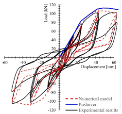 |
| As-Built | Post Renovation | |
|---|---|---|
| Indoor volume | 3 368.77 m3 | 3 029.63 m3 |
| Indoor floor area | 676.45 m2 | 608.32 m2 |
| Wall surface bordering with the outdoor | 358.71 m2 | 352.10 m2 |
| Glazed surface bordering with the outdoor | 273.44 m2 | 245.77 m2 |
| Number of apartments per floor | 10 | 7 |
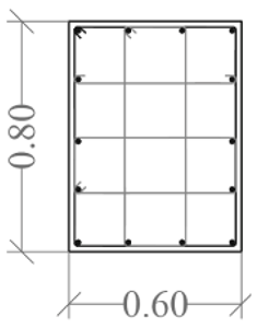
| Columns −1/4 floor | Columns 5/9 floor | |||||
|---|---|---|---|---|---|---|
 |  | 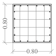 |  | |||
| Column ID | KZ1 | KZ2 | KZ1 | KZ2 | ||
| Long. Rebar | 4ϕ22 + 16ϕ20 | 4ϕ25 + 28ϕ22 | 4ϕ22 + 16ϕ20 | 4ϕ22 + 20ϕ20 | ||
| Stirrups | ϕ10 100 | ϕ10 90 | ϕ10 100 | ϕ10 200/200 | ||
| Columns 10/14 floor | Columns 15/19 floor | |||||
 |  | 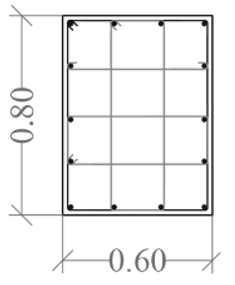 | 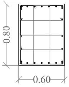 |  |  | |
| Column ID | KZ1 | KZ2 | KZ1 | KZ2 | ||
| Long. Rebar | 4ϕ22 + 16ϕ20 | 4ϕ22 + 22ϕ18 | 8ϕ25 + 6ϕ20 | 18ϕ25 + 6ϕ20 | 8ϕ20 + 6ϕ18 | 14ϕ25 + 6ϕ20 |
| Stirrups | ϕ8 100 | ϕ8 100 | ϕ8 100 | ϕ8 100 | ϕ8 90/180 | ϕ8 90/180 |
| Existing bare frame F UNIF | D | F | K | ED,S | ES,S | veq,s | |
| m | kN | kN/m | KJ | KJ | - | ||
| 0 | 0 | 1284 | 340.75 | 3.0 | |||
| Dsy,Fsy | y | 0.2 | 1300 | 6500.0 | |||
| D,F(D) | max | 0.5 | 1450 | 3085.1 | |||
| Existing bare frame MODE 1 | D | F | K | ED,S | ES,S | veq,s | |
| m | kN | kN/m | KJ | KJ | [-] | ||
| 0 | 0 | 1153,6 | 331,2 | 2,7 | |||
| Dsy,Fsy | y | 0.2 | 900 | 4500.0 | |||
| D,F(D) | max | 0.6 | 1150 | 1996.5 | |||
| Retrofitted structure F UNIF | D | F | K | ED,S | ES,S | veq,s | |
| m | kN | kN/m | KJ | KJ | - | ||
| 0 | 0 | 1298 | 382.5 | 2.7 | |||
| Dsy,Fsy | y | 0.2 | 1420 | 7675.7 | |||
| D,F(D) | max | 0.5 | 1700 | 3777.8 | |||
| Retrofitted structure MODE 1 | D | F | K | ED,S | ES,S | veq,s | |
| m | kN | kN/m | KJ | KJ | - | ||
| 0 | 0 | 1696 | 483 | 2,8 | |||
| Dsy,Fsy | y | 0.2 | 1000 | 5263,2 | |||
| D,F(D) | max | 0.7 | 1400 | 2029,0 | |||
Publisher’s Note: MDPI stays neutral with regard to jurisdictional claims in published maps and institutional affiliations. |
© 2021 by the authors. Licensee MDPI, Basel, Switzerland. This article is an open access article distributed under the terms and conditions of the Creative Commons Attribution (CC BY) license (https://creativecommons.org/licenses/by/4.0/).
Share and Cite
Contiguglia, C.P.; Pelle, A.; Lai, Z.; Briseghella, B.; Nuti, C. Chinese High Rise Reinforced Concrete Building Retrofitted with CLT Panels. Sustainability 2021, 13, 9667. https://doi.org/10.3390/su13179667
Contiguglia CP, Pelle A, Lai Z, Briseghella B, Nuti C. Chinese High Rise Reinforced Concrete Building Retrofitted with CLT Panels. Sustainability. 2021; 13(17):9667. https://doi.org/10.3390/su13179667
Chicago/Turabian StyleContiguglia, Carlotta Pia, Angelo Pelle, Zhichao Lai, Bruno Briseghella, and Camillo Nuti. 2021. "Chinese High Rise Reinforced Concrete Building Retrofitted with CLT Panels" Sustainability 13, no. 17: 9667. https://doi.org/10.3390/su13179667