Abstract
The supply of PV power that satisfies the needs of customers is heavily dependent on the reliability of the generating plants. However, irrespective of the robustness of the design of such physical industrial assets, they tend to depreciate with usage and/or age which, in turn, increases the allowance between the design and the operational capabilities. Therefore, to ameliorate the reliability of the system, a combination of selective and preventive maintenance actions were planned by determining the best combination (optimal preventive maintenance intervals, optimal replaced components). In this work, we developed an optimal preventive maintenance strategy with minimal repair using the iterative numerical technique for a PV plant, with and without considering the influence of environmental conditions on the system. An algorithm was developed on MATLAB to determine the optimal number of preventive maintenance actions that yields the maximum availability by selecting the components to be maintained based on the reliability threshold, without considering the environmental impact on the components. The environmental elements’ criticality was introduced, and the reliability reiterated based on the new technique. Finally, by maximizing the availability of the system, an optimal preventive maintenance for a finite horizon was established.
1. Introduction
Nowadays, the conventional energy sector has become a very challenging area because of its high environmental impact. This energy generation mode brings into question air pollution, which causes an increase in the greenhouse effect that, in turn, causes global warming. This has caused renewable energy sources to gain attention, thereby necessitating the provision of various alternative energy sources, including photovoltaics, wind energy, and concentrated solar power (CSP), among others. Solar energy is the most abundant renewable energy source and appears to be one of the most exploited renewable energy sources, especially for electricity generation globally [1], reaching approximately 227 GW plant installations worldwide [2]. The increased growth rate of PV exploitation has increased the attention of investors, government organizations, and other stakeholders, whose aim is to ensure that a PV system should reliably and cost-effectively generate energy while being sustainable. Failures of critical assets are sometimes catastrophic and result in extended downtime, which are disadvantageous for the financial outcome of investments, client satisfaction, safety, and sustainability. One of the United Nation’s Sustainable Development Goals (SDGs) is the provision of affordable clean energy. This emphasizes the need for the sustainability and criticality of renewable energy generation with cleaner technologies [3]. Sustainability is, therefore, a very important factor for PV-generating plants, and industries in general.
Maintenance is an important parameter for sustainable production in industrial systems, as it ensures continuous operations through reliability, and plant and machines/components failures. Mukhtar et al. [4] carried out a techno-economic feasibility study on a 500 kW PV micro grid integrated into the electric system to determine the effect of electricity consumption on the economic development and environmental sustainability across 12 cities in Nigeria. The sustainable selective maintenance technique was proposed by Duran and Duran [5] for an industrial manufacturing system by a technique known as the Overall Equipment Effectiveness index. This technique was used to determine the effects of maintenance decisions, as well as their operational implications. Another work by Esotu and Kaltingo [6] proposed a quantitative and qualitative hybrid model that analyzes the criticality assessment values of major overhauls, outages, shutdowns, and turn-arounds (MOOST) activities that effectively benefits from criticality assessment to reduce task uncertainties in a system, either in plants or businesses. To properly increase sustainability and improve reliability, plant disaster and system failure analysis should be ensured [7].
Reliability, availability, and maintainability (RAM) assessment is usually implemented in order to ensure the maximum availability of the photovoltaic energy production at all times [8]. Reliability and maintainability are important in measuring the effectiveness of systems. The major difference between reliability and maintainability is that reliability is the probability that a failure will not occur in a particular time, while maintainability is the probability that the required maintenance will be successfully accomplished within a given time period. Maintainability is a design characteristic that affects the accuracy, ease, and time requirements of maintenance actions, which may be measured by combining factors, such as maintenance frequency, maintenance costs, repair times, and labor hours [9].
All systems, equipment, and the functionality of components tend to wane with usage and age. Preventive maintenance (PM) is often implemented to improve overall system reliability and availability. PM scheduling plays a very important role in the successful, economical, and reliable operation of engineering systems. When maintenance actions are rarely performed, especially imperfect maintenance, frequent system failures occur resulting in long downtimes that affect the availability of the system, as well as the financial benefit associated with it. However, when performed too often, maintenance actions can cause material wastage and a considerable increase in maintenance costs. Optimal scheduling becomes necessary in order to strike a balance between the cost of maintenance and material usage and reducing downtime to maximize availability. These are critical decision variables for any preventive maintenance policy.
In a system comprised of different subsystems and subcomponents, it is important to establish a maintenance strategy to find the maintenance priority of components within available resources. Due to constrained resources, not all possible maintenance actions can be performed on a system [10], which makes it imperative to optimally select the component to be maintained. With regard to ensuring the sustainable availability of the PV power plant, this work deals with optimizing selective PM action and ensuring maximum availability, bearing in mind that a reliability threshold is the key decision variable for the maintenance action. The impact of environmental conditions on the reliability was also assessed as an extension of this work.
Although the PV reliability notion was recognized about four decades ago [11], its significance over an entire PV generation system remains vague because of the complex nature of PV systems. Therefore, reliability analysis represents a decisive issue for system planning. The majority of the existing literature is focused on the reliability assessment of different subsystems, such as the inverter [12], the PV module [13,14], and the balance of systems (BOS) [15]. Much less research discusses the reliability evaluation for an entire PV system. Simplified system-level models for PV system reliability using a Markov modeling concept was presented by [16]. Periodic PM scheduling for the service life of a mechanical series system was optimized by [17], where they defined a formula to calculate the redundant life of the series that was used as the criterion for replacement selection.
The PM action model was developed by [18] to maximize system availability during each interval by formulating a constant value used as an improvement factor. Their model was based on the assumption that the time interval for the component with the least life in a series system is to be considered the maintenance interval period. However, this was considered uneconomical because of high maintenance costs and material wastage. Vaurio [19] explored the time-dependent unavailability of sporadically tested aging components under different testing and repair policies. An age diagnostic based renewal strategy was determined by Legat et al. [20] for an optimal PM strategy defined over a finite time horizon.
Vatn et al. [21] optimized the maintenance of an energy production system, taking into account safety and the environment, by minimizing production/maintenance costs. Further studies have treated both predictive and preventive maintenance using a multi-objective optimization model to power distribution networks. The reliability and availability of PV systems by means of general reliability analysis methods were studied by [22,23]. The fault tree method with an exponential probability distribution function was used to analyze the components of 7 large-scale PV systems in [23]. The method serves as a suitable tool for identifying the most critical components of PV systems and helps in identifying areas that planned maintenance should be focused on. The quantitative risk analysis technique was used by [22] on a 20 kW grid-connected PV system over a 25-year period to analyze the system and to assist in developing better maintenance strategies and, thus, to realize the maximum benefit of photovoltaic power.
A failure mode and effects (Critical) analysis (FME(C)A) was applied to a reliability centered maintenance (RCM) to conserve the reliability of a PV system by failure modes identification. The result obtained was used to calculate the risk priority number (RPN) of the system, which served as the decision variable of the maintenance [24]. Different models and maintenance strategies were developed by many researchers [17,18] in order to attain optimal preventive maintenance actions by means of cost optimization and a selective preventive maintenance strategy. Baklouti et al. [25] developed a strategy that determines the optimal number of PV panels to be maintained during each PM action, as well as optimal periodicity T*, which is performed over a finite horizon at minimal cost. The authors suggested that PM policy performs best when the utilization time (horizon) is long. A grid-connected solar PV system maintenance optimization policy was reported by [26]. The authors developed the maintenance cost minimization optimization, based on a two-layered approach, by first calculating the aging cost penalty, which was subsequently used as an input to calculate the optimal maintenance cost. We observed that very few studies focus on availability-based maintenance strategies and, to the best of our knowledge, most of them focus on cost minimization. We have also not found any work that considers the influence of environmental conditions on the reliability/availability of a PV system.
The goal of this work is to propose a new model for PM strategy that maximizes the availability of a PV system. Using the model, we first determine the optimal number of periodic preventive maintenance actions N*, as well as the periodicity T*, within a chosen finite time horizon H, respecting the reliability threshold. The relationship between T* and N* is shown as [27]:
Thus, a selective maintenance decision to choose the best components to be replaced during each action in order to guarantee that maximum reliability/availability is achieved. The proposed model determines the components within the system to be maintained during any maintenance period. Additionally, we will explore the influence of environmental conditions on the reliability/availability of the system in the second part of the work. The originality of this work is that it considers a combined preventive and selective maintenance strategy by determining the best combination for the optimal number of preventive maintenance actions, as well as which components are to be replaced. Accordingly, a perfect preventive maintenance action is considered when all the components are replaced during this action, which restores the photovoltaic system to a good-as-new state. Otherwise, it is considered to be an imperfect preventive maintenance action. There is an important originality in studying the impact of environmental factors on the combined preventive and selective maintenance strategy.
Thus, the work is organized as follows: Section 2 explains the PV system, the components considered, the assumptions made, and the concept of a selective/preventive maintenance strategy; Section 3 discusses the availability and reliability modeling approaches within the study under nominal conditions, as well as environmental assessment conditions; Section 4 provides details on the optimization algorithm used to determine the optimal combination (the number of PM actions and the selected components to be replaced); A numerical example, as well as the result discussions, are presented in Section 5; and Section 6 concludes the study.
2. PV System Description and Assumptions Made
2.1. PV System and the Failure Causes
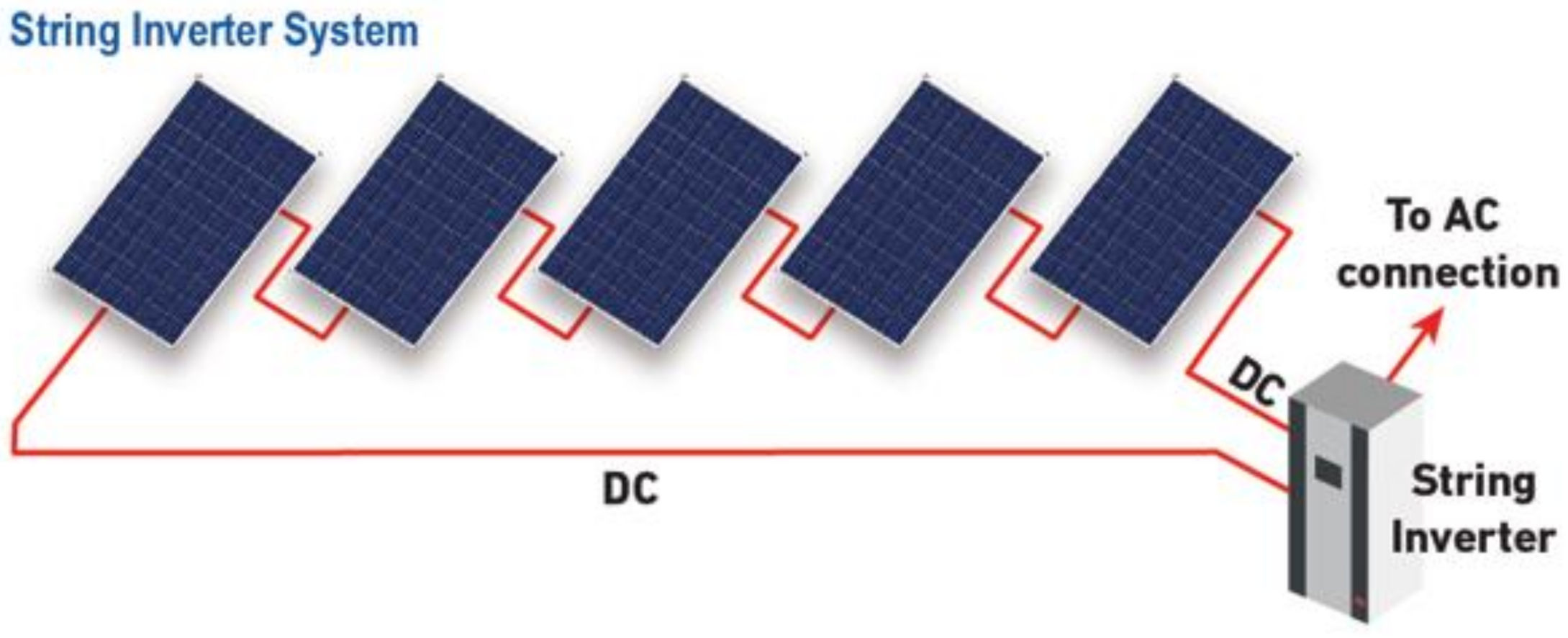
A typical photovoltaic plant is a complex system composed of different electronic devices, in particular, photovoltaic modules and inverters, the reliabilities of which are studied throughout this work. Generally, the photovoltaic modules are connected either in series, in parallel, or as a combination of both. When connected in series, they ameliorate the voltage, while an in parallel connection ameliorates the current. Different modules are connected in series to improve the intensity of the formation of photovoltaic field. As the output of the photovoltaic field is a direct current, the series are connected, via DC wires, to the inverters, which are then used to convert the output to an alternative current (AC). The output from the inverters is transported via AC wires to the load. Figure 1 is a simplified scheme of a PV plant.
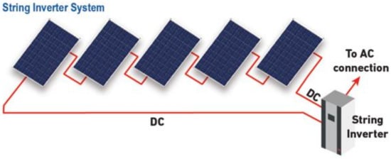
Figure 1.
A PV field layout.
PV panels, AC and DC wires, and inverters are considered in order to reduce the complexity of the reliability computing in this work. As mentioned earlier, the objective of this work is to maximize the system availability and to explore the environmental influence on the reliability of the photovoltaic system. Major PV failures were identified and presented in [28]. In their work, the authors developed a geographic information system (GIS) to automate the identification and supervision of the evolvement of the failures. Thus, we have adopted the major failures identified by [28] for each component we are studying, and the environmental elements influencing those failures. The photovoltaic modules or panels are the most important devices of the photovoltaic system. They have various components, such as photovoltaic cells, interconnectors, a diode bypass, a junction box, a protective glass on both sides, and ribbons. Their main failures are the components failures: the hotspot (an under-irradiated part of the panel that behaves as a receiver that causes a heating of the zone); delamination (separation of the bond between the plastics on the back and the glass on the front of the panel that allows air and moisture to creep inside); and discoloration and corrosion due to chemical reactions. The same failure causes are considered for the DC and AC wires: cut and corrosion. Finally, the inverter does not have detailed failure causes. Table 1 matches each failure with the weather elements influencing its failure cause.

Table 1.
Failures and the type of environmental element(s) influencing the failure.
An optimal selective preventive maintenance strategy with minimal repair for random failures was developed and applied to an electrical production system composed of several solar panels in a series structure. Indeed, in a situation such as the failure of various photovoltaic system components, a minimal repair is applied, characterized by a corrective maintenance action, in order to resume operation of the photovoltaic system with the same failure rate it had before failure. This is called “as bad as old” [29]. In order to reduce the probability of failure, as well as the average number of failures of the photovoltaic system, systematic periodic preventive maintenance was developed. For each preventive maintenance action, this work developed a priority selective maintenance strategy to choose and replace the most degraded components so as to guarantee maximal availability. Therefore, our strategy is characterized by a corrective maintenance (CM) action with minimal repair in case of random failure during the production period. The PM actions are planned periodically and performed at designated times characterized by selective action. At the same time, a minimal repair considered by a palliative action puts it back into service by quickly adjusting or replacing certain elements, such as the photovoltaic cells, interconnectors, diode bypass, junction box, diodes or wires, without improving its reliability and reducing its failure rate.
We want to determine the optimal number of preventive maintenance actions that maximizes the photovoltaic system availability. More precisely, the maintenance strategy adopted consists of systematically replacing a certain number of the photovoltaic system components at different time units, with different components replaced each time, depending on the component’s reliability. The failures that the global system can suffer are generally malfunctions, cable breaks, and a poor power supply.
2.2. Assumptions
- The horizon is finite (H)
- PM has equal time intervals at T, 2 T, up to H.
- The system, and the components within, are in a binary state, that is, they are either working or failed.
- Minimal repair is performed as soon as a component fails during a mission.
- After replacement, a component is ‘‘as good as new”. When minimal repair is performed, it becomes ‘‘as bad as old’’.
- A perfect maintenance is performed when Nc components are replaced; otherwise, an imperfect maintenance is performed.
- All failures are assumed to be random and independent.
- For the failure of electrical components, the reliability is exponentially distributed with a constant failure rate, while the Weibull distribution is used for other types of failures.
- The failure rate of the same components is the same.
- For equipment having various causes, the reliability is assumed to be the product of the reliabilities of all the causes.
2.3. Selective Maintenance
This section is aimed at establishing the optimal selective maintenance with a high reliability level to ensure that the next energy production periods run without discontinuity, considering the obtained reliability estimation of the photovoltaic system under operating and environmental conditions. For this purpose, the photovoltaic is considered a multicomponent system and the components are only maintained in the predetermined optimal maintenance periods (N) that was computed in the preventive maintenance strategy. At each selective maintenance period (k = 1, 2, …, N*), the objective of priority selective maintenance is to select the right components (I = 1, 2, …, Nc) to be maintained, so that a required reliability level is guaranteed until the next shutdown.
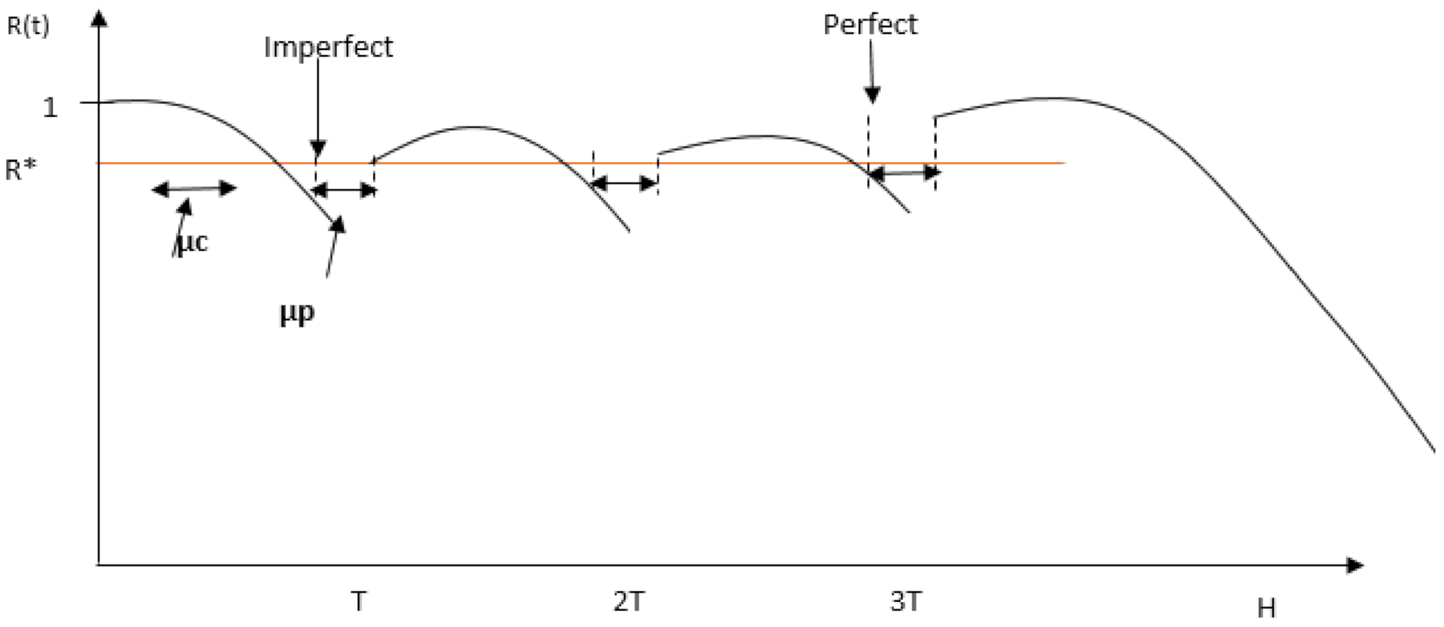
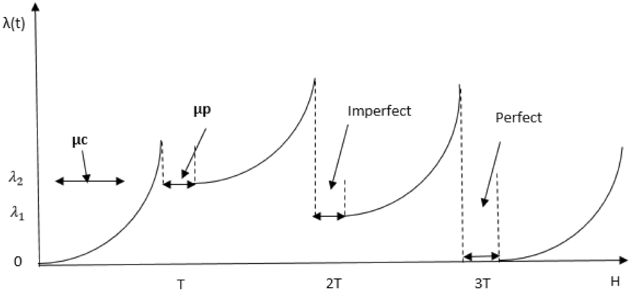
Figure 2 illustrates the typical reliability system evolution of preventive maintenance. When the reliability of a system falls below a certain minimum threshold R*, maintenance is performed on the components depending on the required maintenance type. If, for example, as in Figure 2, when maintenance is carried out at T and 2 T, some components only require servicing and/or repairs and, in that case, imperfect maintenance is carried out. This increases the system reliability by making it younger, but not completely new. At H, the type of maintenance carried out is the perfect maintenance that occurs when all the components are replaced. At this point, the system becomes completely as good as new (AGAN). The failure rate, however, decreases with an increase in maintenance, as illustrated in Figure 3. As such, it is minimized when imperfect maintenance is performed, and it becomes nearly zero (except if manufacturing failure occurs) when a perfect maintenance is performed. For example, from the illustration in Figure 3, the failure rate drops to λ_2 when an imperfect maintenance action is performed at T, assuming one component is replaced, and at 2 T, assuming two or more components are replaced, and minimal repair is performed on the other components. When the failure rate drops to λ_1, and at T3, a perfect maintenance is performed, when all the components are replaced and the failure rate becomes 0.
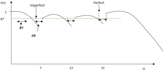
Figure 2.
Illustration of the PM action on reliability considering both imperfect and perfect maintenance.
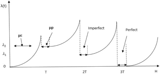
Figure 3.
Illustration of the failure rate as a function of PM time.
3. Problem Formulation
3.1. Availability Formulation
The objective of this work is the optimal scheduling of maintenance actions for a photovoltaic plant. Maintenance scheduling, in this context, is the determination of the time interval, or periodicity, and the type of action to be performed during PM, since we are considering both perfect and imperfect maintenance. For this purpose, the problem of the availability maximization constrained to the reliability threshold was considered. In this section, a mathematical model is developed to express the availability of the photovoltaic system as a function of the decision variables, the optimal number of preventive maintenance actions N*, and the component to be replaced if it is to be maintained based on the reliability threshold. The availability of the system is expressed as follows:
where , and H is the finite horizon time.
As shown in Figure 2 and Figure 3, is the total time taken to perform the designated PM action, while is the sum period for the corrective maintenance for random failures that may occur during the production period, before a PM is performed, and lasts only for the time designated to resuscitate the broken component.
Here, the preventive maintenance time () can be defined as the sum of the duration of the following jobs:
- Access time (t1): this is the time required to gain access to, and identify, the failed component to be maintained by disassembling the system.
- Inspection time (t2): the time required to determine and diagnose the cause of failure.
- Replacement (or repair) time (t3): once the component has been identified and inspected, this is the actual time of carrying out the main PM activity, either repair or replacement, depending on the manager’s decision.
- Assembling time (t4): this is the last stage consisting of the verification, alignment, and assembling of the dismantled system to get it back up into operation.
Furthermore, the corrective maintenance time (μc), in addition to the above-mentioned times, incurs additional time since the failure occurs unexpectedly [18]. The additional times are stated as follows:
- Supply delay time (t5): the time delay in obtaining necessary spare parts or components.
- Maintenance delay time (t6): the time spent waiting for the maintenance personnel, resources, and facilities to be in place.
It was observed that the availability is inversely proportional to the maintenance duration. Therefore, the problem is remodeled as:
subject to R(t) > R* ∀t.
The aim of this work is to maximize the availability of the system keeping in mind that the reliability of the photovoltaic system should be greater than a fixed minimum value called R*. Thus, the problem is formulated as follows:
where:
subject to
is a binary vector string for the components, such that it equals 1 if the component is to be replaced, and 0 when it is not to be maintained. The average number of failures is expressed as follows:
where:
3.2. Photovoltaic Reliability Estimation
3.2.1. Reliability Probability Estimation
Let T be a random variable referring to the time to failure of an equipment, and let P be the probability of its failure. Keeping in mind the assumptions made above, the reliability of the equipment at t is defined as the probability that the system will not fail before, or at, that instant. R is then the probability that T is greater than t. This is explicated as follows:
The PV system is complex and contains a large number of subassemblies that may be connected in series, in parallel, or even a combination of both. When the subassemblies are connected in series, the overall system will be interrupted in the case of the failure of one subassembly. However, all subassemblies must fail in order to interrupt the overall system in the parallel connected system. For components associated in series, the reliability of the group is assumed to be the product of each component reliability, as shown in (10) [30], Appendix B explains the derivation of Equation (10) for further understanding.
3.2.2. Photovoltaic Plant Reliability
- System Reliability:
As mentioned earlier, a system is composed of a photovoltaic field, Dc wires, inverters, and AC wires associated in series. Thus, the reliability of the whole system is expressed as:
- Photovoltaic Field Reliability:
The photovoltaic field is composed of nseries number of photovoltaic components associated in series. Its reliability has this form:
As the series are identical, their reliability functions are also identical. Thus, the field reliability is equal to:
- Photovoltaic Series Reliability:
A photovoltaic series consisting of npanels panels associated in series has the following form:
- Photovoltaic Panel Reliability:
The reliability function of the photovoltaic panel is expressed as follow:
- DC/AC Wires Reliability:
The DC wires and the AC wires reliability functions are of the same form. As such, they are treated in a similar way:
- Inverter Reliability:
The inverter is a complex and expensive component of a photovoltaic system. The main causes of failure in inverters are mainly design problems, manufacturing defects, and poor management practices [31], even though temperature and humidity can also affect the functionality of the inverter. Thus, low inverter reliability contributes to an unreliable system and a loss of confidence in the renewable technology. The reliability function is described by an exponential distribution and will be explicitly expressed in the next subsection.
3.3. Explicit Reliability Functions
More explicitly, the reliability of components is often characterized by failure rate λ, and is thus expressed in the equation:
It was established, based on [32], that the reliability functions of the different components depend only on time, and are independent of atmospheric conditions; hence, for each component, the explicit reliability functions are given as follows:
3.3.1. PV Panels
For the PV panels, the components and the causes for failure have the same form, given as:
Thus, the reliability of the panel components is expressed by:
The reliability functions related to the discoloration and corrosion failures are expressed as follows:
Thus, Rcause is expressed by:
Those failures are due to chemical reactions, and this is the reason for using different probability distributions.
3.3.2. DC/AC Wires
The wires have two failure causes: cut and corrosion. For each cause, the reliability function has a different form:
The reliability of the AC and DC wires is then:
3.3.3. Inverter
The reliability function of the inverter is described by an exponential distribution:
3.3.4. Overall PV System Reliability
The reliability of the PV system consisting of the panels, inverters and wires at t is calculated as:
Consequently, the reliability of a photovoltaic power plant is given by:
Moreover, if a maintenance action is applied at the instant with (k: 1,..,N), the reliability of the photovoltaic_plant is expressed:
And, consequently, the reliability of a photovoltaic power plant:
3.4. Photovoltaic Plant Reliability under the Influence of Environmental Conditions
In this section, an in-depth study of the reliability estimation of photovoltaic components as a function of environmental conditions, using a parametric relationship between environmental and risk factors, is carried out. Each climatic factoris associated with a weighting coefficient, that quantifies the influence of climatic conditions on the photovoltaic system. A multiplicative regression model for survival data, known as the Cox regression model, is used to establish the relationship between the reliability function established under nominal climatic conditions (), and the criticality function of j climatic conditions. The Cox model is a statistical tool that was first developed in the medical industry to formulate a relationship between the survival of a patient and several other variables by estimating the effect of treatment on patients and the risks of death after the treatments [29]. To integrate the environmental impact on the reliability function, the criticality coefficient (C) for each failure was defined. The coefficient is the product of the frequency (F), detectability (D), and severity (S) of each failure.
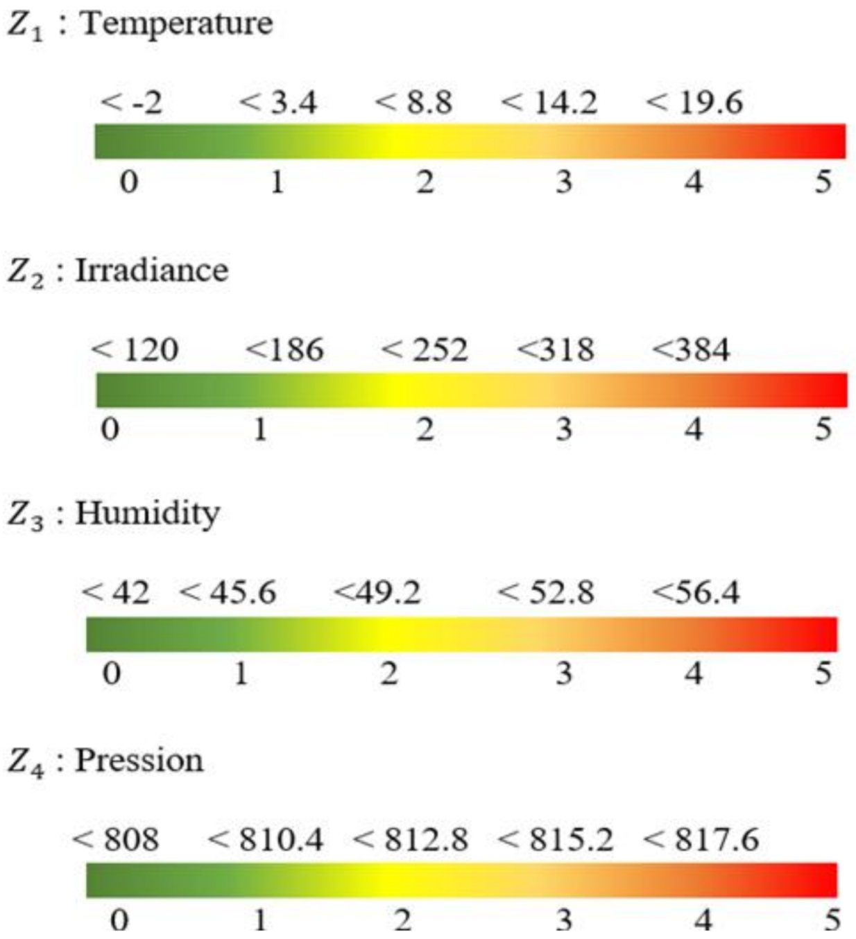
On the basis of the indication of the environmental elements that stimulates each failure type, as shown in Table 1, different values of the criticality coefficient were defined based on the weather data. The environmental data were explored by assigning a value between 0 and 5 to each element, according to its real value. The mathematical expression of the criticality coefficient as a function of the weather elements was established as in (44), and is shown in Figure 4. The idea is to amplify the degeneration of reliability if the environmental conditions are more critical, and recompense if otherwise.
where:
where is the constant of criticality for each component are the criticality values for temperature, humidity, irradiance, and pressure, respectively, as shown in Appendix A. Equation (35) is reconstructed to (36) by dividing Cj by to show the final criticality coefficient given as:
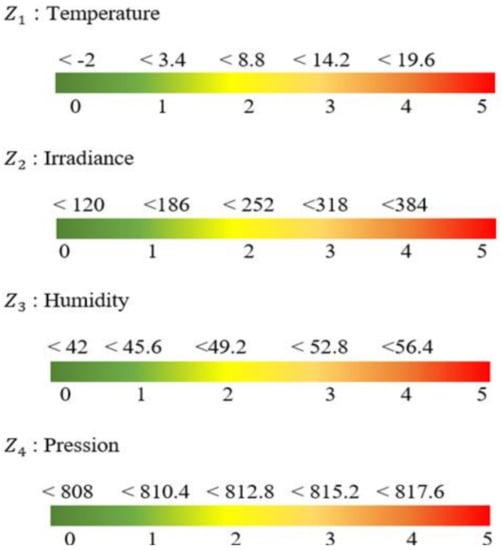
Figure 4.
Criticality coefficient of the weather elements.
The criticality factor (Cj) was integrated into the reliability function equation yielding Equation (37). denotes the reliability function of the component/cause, depending only on time, while is the reliability for nominal environmental conditions. Given that must imperatively decrease over time, we opted for the integration of the previous value of this function. Thus, the following expression was developed for each reliability function related to each failure/component:
where:
: is the vector of environmental elements corresponding to the time instant (t – 1).
And
Thus:
If a maintenance action is applied at the instant with (k: 1,..,N), the reliability of the photovoltaic plant under environmental condition Z is expressed:
4. Optimization Algorithm
To apply an algorithm to a problem, a series of steps have to be clearly defined. There are N number of planned maintenance actions, and the objective is to determine the optimal number of maintenance actions to be carried out in order to achieve maximum availability, while selecting the components to be maintained during each maintenance period depending on the component’s reliability at the time of maintenance, and to explore the influence of environmental conditions on the reliability of the PV system. Furthermore, there is no constraint on the number of components to be maintained during each maintenance period. This is because the life cycle of some components, as well as the degradation factors, are lower than others.
At the beginning of the horizon, all the components are new and are assumed to have high reliability. The maintenance scheduling is planned such that selective maintenance on the components is carried out at the time of the preventive maintenance action, depending on the reliability of the component at that time. A binary vector is constructed for the selection of the component for the maintenance action, which is a finite integer of string m over the planning horizon. Each element of m is one of a possible number of maintenance actions available in the case where one, two, or three components are to be replaced at a time, in which an imperfect maintenance action is performed. In the case where all of the (4) components are to be replaced, the maintenance action then becomes a perfect maintenance. The algorithm calculates the reliability of each component to determine if maintenance should be performed or not. If the verification condition is met, i.e., if the reliability of the component has fallen below the reliability threshold, a string corresponding to the condition of the components is drawn such that the mi(k) of the components selected for maintenance action is assigned a value 1. It is possible to find two identical strings of solution during the planning horizon. Therefore, the vector is constructed in a way that strikes out all duplicates of the string so that maintenance is carried out on each component once during a maintenance action period.
With the solution string constructed, the number of preventive maintenance action (N) was set to Nmax and the threshold of reliability. The algorithm was set in such a way that for each N (1:Nmax) selected, the maintenance time was evaluated using Equation (6). The total maintenance time takes care of both the planned preventive and corrective maintenance times. The availability estimation, as in Equation (5), was subsequently followed. The availability achieved was stored and used as the threshold for the next availability estimation, and if the value of the availability obtained was less than the previous value, the previous value remains the intended availability until a greater value is obtained. In other words, it stores only the maximum availability of the system.
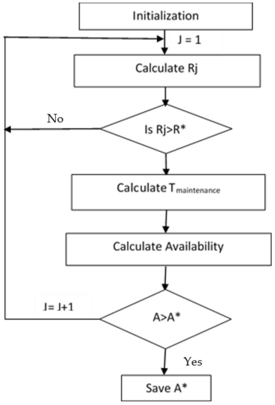
An overview of the algorithm is shown in the flow chart in Figure 5, with the steps outlined below:
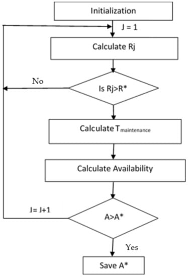
Figure 5.
Algorithm flow chart.
- Initialize the algorithm by defining the total horizon H, reliability threshold R*, and Nmax.
- Set Tmaintenance = 0, j = 1 and generate binary vector m for selective maintenance
- For each value of N, calculate the reliability of the component.
- Check the condition for maintenance; if , no maintenance is required, go to step 8. Otherwise, maintenance will be performed on the component which makes the mi(k) of the component to be 1.
- Calculate the Tmaintenance over the horizon.
- Then calculate the availability.
- If the availability is greater than the previous availability (, the newly calculated availability then becomes the optimal availability (A*).
- Then j = j + 1 and repeat the loop until Nmax is reached. For each value of N, the corresponding availability is recorded and plotted.
5. Numerical Example and Result Discussion
5.1. Numerical Example
Following the numerical optimization procedure based on the algorithm we developed for a finite number of maintenance actions, we propose the following numerical example with arbitrarily chosen values. The constant failure rates of the PV system components and subcomponents are tabulated in Table 2. A PV system consists of three PV modules connected in series, the output is connected to two inverters via DC cables. The inverter output is transmitted to the load via 2 AC cables as well. The reparation rate for each component, and the constant corrective maintenance time, is also tabulated in Table 3. Considering the environmental conditions influencing the components/subcomponents, the criticality coefficient data is given in Appendix A, while the corresponding represented values are shown in Figure 4. For the purpose of illustration and further research, the environmental data from a 55 MW solar power plant in Sokoto, Nigeria, were obtained during the wet season in the month of August. The temperature of the location is about 16.67 °C, the relative humidity is about 63%, the average daily irradiance is about 359.45 W/m2, and the pressure is 916 mbar. This corresponds to 3, 4, 3, 4 for temperature, humidity, irradiance and pressure, respectively, according to Figure 4, and the chosen time horizon is 1000 units of time. The said power plant set-up cost is estimated at $106,600. However, the focus of our paper is on availability. Therefore, using this information, the system availability was determined under two scenarios mentioned as:
Scenario 1: system under nominal condition
Scenario 2: system under environmental condition assessment.

Table 2.
Component/subcomponent constant failure rate.
Table 2.
Component/subcomponent constant failure rate.
| Failure Modedxdcd | Constant Failure Rate (h−1) |
|---|---|
| Hot spot | 7.13 × 10⁻⁷ |
| Diode bypass | 5.85 × 10⁻⁷ |
| Junction box | 7.87 × 10⁻⁷ |
| Delamination | 5.44 × 10⁻⁷ |
| Glass case (broken) | 5.44 × 10⁻⁷ |
| Cell | 7.13 × 10⁻⁶ |
| Soldering tape | 4.84 × 10⁻⁶ |
| Interconnection box b-Discoloration a-Discoloration b-Corrosion a-Corrosion DC cable DC cable Corrosion coefficient AC cable AC cable Corrosion coefficient Inverter | 4.68 × 10⁻⁶ 1.36 × 10⁻²⁰ 3.08 × 10⁻²⁰ 1.61 × 10⁻²¹ 3.08 × 10⁻²⁰ 4.83 × 10⁻⁸ 1.68 × 10⁻⁷ 1.30 × 10⁻⁸ 8.82 × 10⁻⁸ 9.51 × 10⁻⁶ |

Table 3.
PV system components’ repair time(s).
Table 3.
PV system components’ repair time(s).
| Components | PM Time (Units) | CM Time (Unit) |
|---|---|---|
| PV Panel | 0.3 | 15 |
| DC wire AC wire Inverter | 0.2 0.2 0.3 |
5.2. Results and Discussion
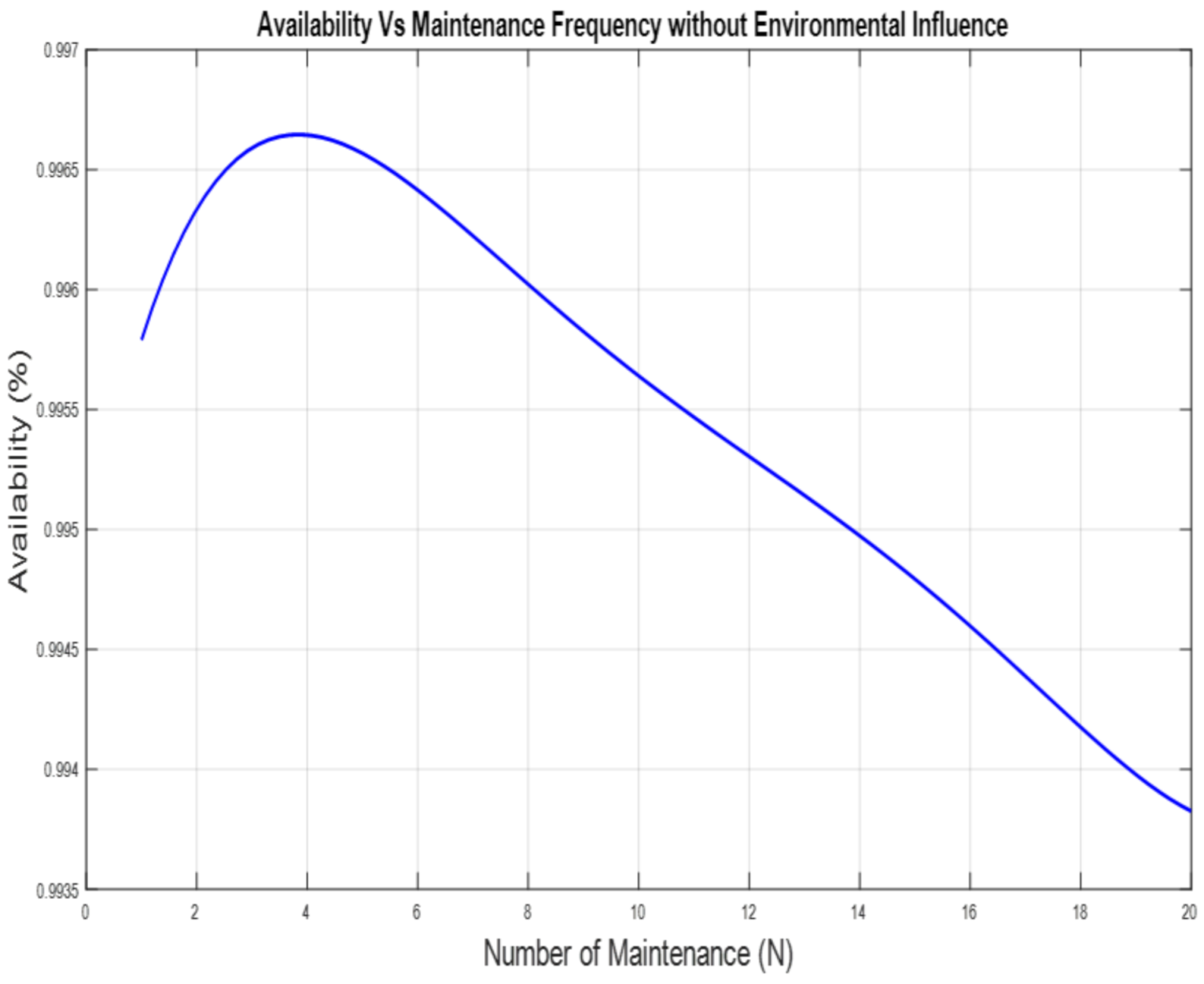
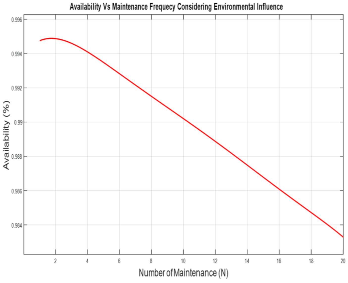
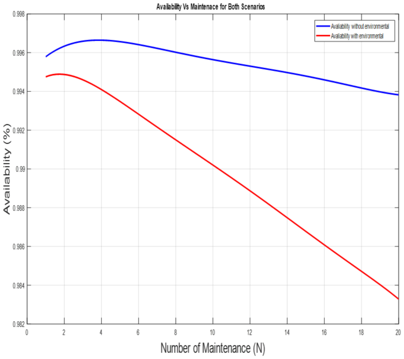
The number of maintenance actions varied from 1 to 20 for both scenarios in order to determine the number that yields maximum availability. The availability (A) was plotted against each number of maintenance (N) for the two scenarios and presented in Figure 6, Figure 7 and Figure 8. As seen in Figure 6, the maximum availability was 99.66%, which corresponds to N = 3, which we considered optimal (N*). For Scenario 2, where the influence of the environmental condition is considered, 99.50% availability was the maximum, and it was obtained when N = 2, which is the N* represented in Figure 7. In Figure 8, it is clear that the system is more available under the nominal condition, even with the increased number of maintenance actions. In Scenario 1, for N is 10, 99.57% availability was achieved, while 99.48% and 99.38% were obtained when N is 15 and 20, respectively. In Scenario 2, however, 99.02% was obtained for N is 10, 99.68% when N is 15, and 98.33% when N is 20. A large number of N was chosen to help us ascertain if the value we obtained was the global maximum and not the local maximum.
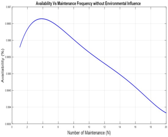
Figure 6.
Availability for PV system under the nominal environmental condition.
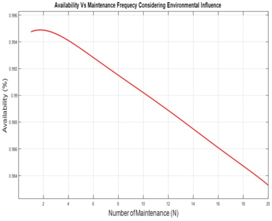
Figure 7.
Availability for the system under the influence of the environmental condition.
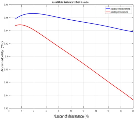
Figure 8.
Availability for the system showing the 2 scenarios.
During each maintenance action, since we assumed that components are replaced (perfect maintance), the system is made almost as good as new when all the components are replaced, making it highly reliable. Since we already know the maximum number of maintenance actions that yields the availability, we therefore calculated the periodicity (length between maintenance missions) as 1000/N*, representing 333 units for Scenario 1, and 500 units for Scenario 2. The components to be replaced were determined by the component’s reliability. From our algorithm, we obtained the results tabulated in Table 4 and Table 5, where we indicated the reliability for each production period, and the components selected to be replaced during each maintenance action.

Table 4.
Replaced components during the PM action in Scenario 1 when N * = 3.

Table 5.
Replaced components during the PM action in Scenario 2 when N * = 2.
In the first action, as shown in Table 4, maintenance action was performed on a PV panel and AC wire during the first streak, thereby making the system reliability 96.08%, and 99.36% during the second streak, while maintenance was performed on the other two remaining components. During the last streak of the maintenance, a perfect maintenance was carried out where all the components were replaced, thereby making the system reliability 99.99%. Whenever a component undergoes maintenance, it has a lower probability of failure and, hence, an increase in the system reliability value is achieved for the next mission. At the last stream, a perfect maintenance was carried out by replacing all components and making the system “AGAN”. In Table 5, maintenance was performed on a PV panel and an inverter during the maintenance break, with the system having 89.38% reliability, with a total component replacement at the end of the horizon.
5.3. Sensitivity Analysis
To validate the algorithm, we decided to test it with different values for the CM times of 10 and 20, with PM times to be 0.2, 0.1, 0.15, and 0.25 for the PV panel, DC and AC wires, and the inverter, respectively. The environmental elements’ coefficients of 3, 4, 4, 1 were selected for temperature, humidity, irradiance and pressure, respectively. The results are tabulated in Table 6 and Table 7. Maximum availability was achieved when N is 5 for Scenario 1, and 2 for Scenario 2, shown in Table 6. With these parameters, N* was observed to have changed from 2 to 5 in Scenario 1, with an availability of 99.83%, which shows an increase from 99.66%, and a reliability of 97.25%. However, in Scenario 2, the N* remained unchanged, but the availability increased from 99.50% to 99.75%, with a reliability of 70.57%. Increased CM, as shown in Table 7, yielded N* is 4 for both scenarios. However, the availabilities were observed to decrease to 99.64% and 99.51% for both scenarios, respectively.

Table 6.
CM time = 10, PM = 0.2, 0.1, 0.15, and 0.25 time units.

Table 7.
CM time = 20, PM = 0.2, 0.1, 0.15, and 0.25 time units.
The reliabilities are seen to be decreasing from 97.25% to 96.58% in Scenario 1, and increasing from 70.57% to 72.72% in Scenario 2. This can be explained by the slight decrease in the periodicity of N from 5 to 4 in Scenario 1, and an increase from 2 to 4 in Scenario 2. Considering the effect of the environment on both the availability and reliability, the effect is more visible on reliability than availability. To further explore the influence of environmental conditions on the system, we constructed a limit of four different vectors arbitrarily and randomly from Figure 4 and tabulated the vectors in Table 8. The results obtained are presented in Table 9 and are used as a comparison to the results obtained in Table 6 and Table 7.

Table 8.
Vector strings for environmental assessment.

Table 9.
Environmental influence with CM = 10, and CM = 20.
The reliability and availability results from the constructed environmental elements’ vector combination in Table 8 are presented in Table 9. From an assessment of the four vectors and their resulting reliabilities, it can be deduced that temperature has the most significant influence on the PV system. When temperature is high (4), as in Vector 1, it yielded reliabilities of 78.84% and 79.93% for CM is 10 and 20, respectively, with the availability being 99.58%. This can be explained by Table 1, where it shows that temperature affects most of the components of the PV system. This means that high temperature yields high reliability, while low temperature yields low reliability. We can also say that humidity plays a vital role, but as a reverse of temperature: when temperature is high, for high system reliability, the humidity should be low, and vice versa. Pressure effects are least even at maximum, as seen for Vectors 2, 3, and 4. In Vector 2, the reliability was found to be 26.70% and 27.50% for CM 10 and 20, respectively, despite maximum available irradiance and pressure. In Vector 3, the reliability increased from 26.70% to 35.10% when CM is 10, and from 27.50% to 36.30% when CM is 20, while humidity was maintained at intermediate values of 2, with a temperature rise and constant pressure. In V4, a drastic drop in reliability was observed, yielding extremely low reliabilities of 13.60% and 14.10%, respectively, despite increasing the humidity and irradiance.
6. Conclusions
This paper presented an algorithm for selective preventive maintenance by considering the reliability threshold. The reliability of each component was calculated at the end of each mission, and the components to be replaced were predetermined. The availability of the system was determined for each scenario under each maintenance action so as to determine the optimal number of maintenance actions that ensures availability. The system reliabilities were also calculated considering the optimal number of maintenance actions while carrying out selective maintenance on the components. For both scenarios, maintenance actions were to be performed on two components during each action. Temperature, humidity, atmospheric pressure, and solar irradiance were found to aggravate failures in the photovoltaic system. Their influence was considered in order to understand the magnitude of the effect on the system availability, as well as on the reliability. It was observed from the simulation result that the system needed to be maintained more frequently in Scenario 2, resulting in ample downtime, as compared with the system in Scenario 1.
The maintenance time was varied for the components as well as for the environmental condition. From the analysis, the temperature proved to be highly influential on the system. When the temperature coefficient was high, as in V1, it yielded high reliabilities of 78.84% and 79.93%, respectively, while in V4, it only yielded 13.60% and 14.10%, respectively, even when other parameters were sufficiently good. Thus, high temperature improves the system reliability within the threshold. The influences an environment has on the PV system were explored, and the relationship with the maintenance time was established. It was evident that the environmental condition affects the reliability of the system significantly but has minimal effect on the availability. To further study this topic, we will consider cleaning action in maintenance scheduling to reduce material wastage by the component replacements method we adopted. We will also look at the cost optimization of maintenance, taking the site mentioned in the example as a case study.
Author Contributions
The methodology of the work was developed by Z.H. and A.C.N.; the algorithm/software development was done by A.S. and A.C.N., A.S.; Z.H. and A.C.N. prepared the original draft preparation and it was validated by Z.H. and A.C.N. All authors have read and agreed to the submission of the manuscript.
Funding
We certify that we have no affiliations or involvement in any organization or entity with any financial and/or non-financial interest in the research presented in this manuscript.
Institutional Review Board Statement
Not Applicable.
Informed Consent Statement
Not Applicable.
Data Availability Statement
All data generated or analyzed during this study are included in this published article.
Conflicts of Interest
The authors declare no conflict of interest.
Nomenclature
| A | Availability |
| H | Production horizon |
| Tmaint | Total maintenance duration |
| R(t) | System reliability at t |
| Cj | Criticality coefficient of the system failure |
| N | Number of maintenance actions |
| Nc | Number of components |
| R* | Minimum required reliability threshold |
| k | Production period |
| Requipment | Reliability function of equipment |
| Rcause | Reliability function of cause of failure for a component |
| R,j(t) | Reliability of the jth component under the effect of environmental condition |
| Ro,j(t) | Reliability of the jth component under nominal condition |
| Co,j | Criticality coefficient of jth component |
| a/bcause | Failure cause constant under chemical influence |
| Preventive maintenance time | |
| Corrective maintenance time | |
| φ(N) | Average Number of failure rate |
| PV system failure rate | |
| Constant failure rate of components/subcomponents | |
| Criticality coefficient vector for component j | |
| Zi | Vector of environmental conditions |
| ZEC | Environmental condition representation |
Appendix A

Table A1.
A table of criticality and Criticality coefficients of the system components and subcomponents.
Table A1.
A table of criticality and Criticality coefficients of the system components and subcomponents.
| Hot Spot | Junction Box | Glass Case | Diode Bypass | Delamination | Cell | Soldering Tape | Interconnection Box | Discoloration | Corrosion | Cut | Corrosion Cable | Inverter | |
|---|---|---|---|---|---|---|---|---|---|---|---|---|---|
| Constant | 3.993 | 2.907 | 1.336 | 3.521 | 1.783 | 1.517 | 1.207 | 1.741 | 3.463 | 2.703 | 1.692 | 1.591 | 1.874 |
| Temperature | 0 | 0.141 | 0.461 | 0 | 0.228 | 0.293 | 0.438 | 0.213 | 0 | 0.153 | 0.365 | 0.133 | 0.395 |
| Irradiance | 0.369 | 0 | 0 | 0.361 | 0 | 0 | 0 | 0 | 0.128 | 0.206 | 0 | 0 | 0 |
| Humidity | 0 | 0.102 | 0 | 0 | 0.319 | 0 | 0.080 | 0.408 | 0.076 | 0 | 0 | 0.338 | 0.179 |
| Pressure | 0 | 0 | 0 | 0 | 0 | 0.170 | 0 | 0 | 0 | 0 | 0 | 0 | 0 |
| Criticality coefficient | 20.415 | 39.100 | 18.584 | 12.997 | 35.743 | 20.516 | 19.154 | 45.093 | 60.161 | 46.679 | 18.440 | 22.952 | 38.384 |
Appendix B. Explanation of the Reliability Equations
In this section, a more explicit reliability derivation equation for the PV system relia-bility is explained. It is thus:
For equipment composed of different components associated in series, unreliability function Q is used to define the reliability of the group. The unreliability of the equipment is the products of each component unreliability:
References
- García, F.P.; Pedregal, D.J.; Roberts, C. Time series methods applied to failure prediction and detection. Reliab. Eng. Syst. Saf. 2010, 95, 698–703. [Google Scholar] [CrossRef]
- Kalogirou, S. Handbook of Photovoltaics: Fundamentals and Applications; Academic Press: London, UK, 2018; ISBN 978-0-12-810397-5. [Google Scholar]
- Hajej, Z.; Rezg, N.; Bouzoubaa, M. An integrated maintenance strategy for a power generation system under failure rate variation (case of wind turbine). In Proceedings of the 2017 IEEE 6th International Conference on Renewable Energy Research and Applications (ICRERA), San Diego, CA, USA, 5–8 November 2017; pp. 76–79. [Google Scholar]
- Mukhtar, M.; Obiora, S.; Yimen, N.; Quixin, Z.; Bamisile, O.; Jidele, P.; Irivboje, Y.I. Effect of Inadequate Electrification on Nigeria’s Economic Development and Environmental Sustainability. Sustainability 2021, 13, 2229. [Google Scholar] [CrossRef]
- Durán, O.; Durán, P.A. Prioritization of Physical Assets for Maintenance and Production Sustainability. Sustainability 2019, 11, 1–16. [Google Scholar]
- Iheukwumere-Esotu, L.; Yunusa-Kaltungo, A. Knowledge Criticality Assessment and Codification Framework for Major Maintenance Activities: A Case Study of Cement Rotary Kiln Plant. Sustainability 2021, 13, 4619. [Google Scholar] [CrossRef]
- Iglesias-Mendoza, M.; Yunusa-Kaltungo, A.; Hadleigh-Dunn, S.; Labib, A. Learning How to Learn from Disasters through a Comparative Dichotomy Analysis: Grenfell Tower and Hurricane Katrina Case Studies. Sustainability 2021, 13, 2030. [Google Scholar] [CrossRef]
- Dhillon, B.S. Maintainability, Maintenance, and Reliability for Engineers; CRC Press, Taylor & Francis Group: Boca Raton, FL, USA, 2006; pp. 143–160. [Google Scholar]
- Baschel, S.; Koubli, E.; Roy, J.; Gottschalg, R. Impact of Component Reliability on Large Scale Photovoltaic Systems’ Performance. Energies 2018, 11, 1579. [Google Scholar] [CrossRef] [Green Version]
- Pandey, M.; Zuo, M.J.; Moghaddass, R. Selective maintenance scheduling over a finite planning horizon. Proc. Inst. Mech. Eng. Part O J. Risk Reliab. 2016, 230, 162–177. [Google Scholar] [CrossRef]
- Stember, L.H.; Huss, W.R.; Bridgman, M.S. A Methodology for Photovoltaic System Reliability & Economic Analysis. IEEE Trans. Reliab. 1982, R-31, 296–303. [Google Scholar]
- Alonso, R.; Roman, E.; Sanz, A.; Santos, V.E.M.; Ibanez, P. Analysis of Inverter-Voltage Influence on Distributed MPPT Architecture Performance. IEEE Trans. Ind. Electron. 2012, 59, 3900–3907. [Google Scholar] [CrossRef]
- Wohlgemuth, J.; Cunningham, D.; Monus, P.; Miller, J.; Nguyen, A. Long Term Reliability of Photovoltaic Modules. In Proceedings of the 2006 IEEE 4th World Conference on Photovoltaic Energy Conference, Waikoloa, HI, USA, 7–12 May 2006; pp. 2050–2053. [Google Scholar]
- Dhere, N.G.; Shiradkar, N.; Schneller, E.; Gade, V. The Reliability of Bypass Diodes in PV Modules. In Proceedings of the Reliability of Photovoltaic Cells, Modules, Components, and Systems VI, San Diego, CA, USA, 25 August 2013; Dhere, N.G., Wohlgemuth, J.H., Lynn, K.W., Eds.; p. 882501. [Google Scholar] [CrossRef]
- Cristaldi, L.; Khalil, M.; Faifer, M.; Soulatiantork, P. Markov process reliability model for photovoltaic module encapsulation failures. In Proceedings of the 2015 International Conference on Renewable Energy Research and Applications (ICRERA), Palermo, Italy, 22–25 November 2015; pp. 203–208. [Google Scholar]
- Dhople, S.V.; Davoudi, A.; Chapman, P.L.; Dominguez-Garcia, A.D. Integrating photovoltaic inverter reliability into energy yield estimation with Markov models. In Proceedings of the 2010 IEEE 12th Workshop on Control and Modeling for Power Electronics (COMPEL), Boulder, CO, USA, 28–30 June 2010; pp. 1–5. [Google Scholar]
- Tsai, Y.-T.; Wang, K.-S.; Teng, H.-Y. Optimizing preventive maintenance for mechanical components using genetic algorithms. Reliab. Eng. Syst. Saf. 2001, 74, 89–97. [Google Scholar] [CrossRef]
- Tsai, Y.-T.; Wang, K.-S.; Tsai, L.-C. A study of availability-centered preventive maintenance for multi-component systems. Reliab. Eng. Syst. Saf. 2004, 84, 261–270. [Google Scholar] [CrossRef]
- Vaurio, J.K. On time-dependent availability and maintenance optimization of standby units under various maintenance policies. Reliab. Eng. Syst. Saf. 1997, 56, 79–89. [Google Scholar] [CrossRef]
- Legát, V.; Žaludová, A.H.; Červenka, V.; Jurča, V. Contribution to optimization of preventive replacement. Reliab. Eng. Syst. Saf. 1996, 51, 259–266. [Google Scholar] [CrossRef]
- Vatn, J.; Hokstad, P.; Bodsberg, L. An overall model for maintenance optimization. Reliab. Eng. Syst. Saf. 1996, 51, 241–257. [Google Scholar] [CrossRef]
- Li, S. Condition-Dependent Risk Assessment of Large-Scale Grid-Tied Photovoltaic Power Systems. Master’s Thesis, The Pennsylvania State University, Statecolich, PA, USA, 2012. [Google Scholar]
- Ahadi, A.; Ghadimi, N.; Mirabbasi, D. Reliability assessment for components of large scale photovoltaic systems. J. Power Sources 2014, 264, 211–219. [Google Scholar] [CrossRef]
- Colli, A. Failure mode and effect analysis for photovoltaic systems. Renew. Sustain. Energy Rev. 2015, 50, 804–809. [Google Scholar] [CrossRef]
- Baklouti, A.; Mifdal, L.; Dellagi, S.; Chelbi, A. An Optimal Preventive Maintenance Policy for a Solar Photovoltaic System. Sustainability 2020, 12, 4266. [Google Scholar] [CrossRef]
- Mahani, K.; Liang, Z.; Parlikad, A.K.; Jafari, M.A. Joint Optimization of Operation and Maintenance Policies for Solar-Powered Microgrids. IEEE Trans. Sustain. Energy 2019, 10, 833–842. [Google Scholar] [CrossRef] [Green Version]
- Hajej, Z.; Nyoungue, A.C.; Abubakar, A.S.; Mohamed Ali, K. An Integrated Model of Production, Maintenance, and Quality Control with Statistical Process Control Chart of a Supply Chain. Appl. Sci. 2021, 11, 4192. [Google Scholar] [CrossRef]
- de Simón-Martín, M.; Diez-Suárez, A.-M.; Álvarez-de Prado, L.; González-Martínez, A.; de la Puente-Gil, Á.; Blanes-Peiró, J. Development of a GIS Tool for High Precision PV Degradation Monitoring and Supervision: Feasibility Analysis in Large and Small PV Plants. Sustainability 2017, 9, 965. [Google Scholar] [CrossRef] [Green Version]
- Benazzouz, A.; Barhdadi, A.; Fabrizio, B.; Verdilio, D. Development of an Advanced Preventive Maintenance Plan for Grid-connected High Concentration Photovoltaic Power Plant. Afr. Rev. Phys. 2016, 11, 8. [Google Scholar]
- Shenoy, P.S.; Kim, K.A.; Johnson, B.B.; Krein, P.T. Differential Power Processing for Increased Energy Production and Reliability of Photovoltaic Systems. IEEE Trans. Power Electron. 2013, 28, 2968–2979. [Google Scholar] [CrossRef]
- Realini, A. Mean Time Before Failure of Photovoltaic modules. Final. Rep. Fed. Off. Educ. Sci. Tech. Rep. BBW 2003, 99, 58. [Google Scholar]
- Al-Rawi, N.A.; Al-Kaisi, M.M.; Asfer, D. Reliability of photovoltaic modules I. Theoretical considerations. Sol. Energy Mater. Sol. Cells 1994, 31, 455–468. [Google Scholar] [CrossRef]
Publisher’s Note: MDPI stays neutral with regard to jurisdictional claims in published maps and institutional affiliations. |
© 2021 by the authors. Licensee MDPI, Basel, Switzerland. This article is an open access article distributed under the terms and conditions of the Creative Commons Attribution (CC BY) license (https://creativecommons.org/licenses/by/4.0/).

